Hi-Target ZTS-320 Series User manual

1
Preface
Thank you for purchasing our ZTS-320 series total station!
This manual is your good helper, please read it before operate
the instrument and keep it properly.
Product Validation
In order to get our best service, please give the feedback
about the version, number and purchasing date of the instrument
and your valuable suggestions to us after you purchase our
product.
We will attach great importance to every piece of advice
from you!
We will pay much attention to every detail of our products!
We will make great efforts to provide better quality!
Notice: We reserve the right to change the technical
parameters during updating and improving our products and we
may not announce you in advance. The Pictures in this manual is
for reference only, please in kind prevail.

2
Features
Rich Features--- Our ZTS-320series total station carries
abundant surveying applications ,at the same time has the
functions of data storage, parameter settings and etc .It‟s suitable
for all kinds of professional measurements.
1. Absolute code disc
Equipped with absolute code disc , the instrument can
measure after switched on .Even if reset the battery halfway,
the azimuth information will not be lost.
2. A high-capacity RAM Management
It serves an easy management for file system, including the
increase, deletion and transmission of data.
3. Non- prism distance measuring
With non-prism distance measuring, this series total station
can be directly to all kinds of material, different colors of
objects (such as the structure of the walls, poles, wires, cliff
wall, mountain, clay, wood, etc.) for long, fast, high
precision measurement .This function is especially for the
measurements of targets that cannot be accessed.
4.Special measurement program
Except for the basic functions, it also has some special
measurement program to meet the needs of professional
measuring, such as Remote Height (REM) Measurement,
Offset Measurement, MLM (MLM Measurement),
Resection,Area measurement calculation, Roadway design
and staking-out .
5. Changeable eyepiece
As the eyepiece is changeable, it is convenient to be
equipped with diagonal eyepiece, which makes it easy to
you to observe the zenith direction high-rise buildings
6. Laser plumb
Easy to direct the station point and free station

3
Notice:
a) Do not look directly into the sun with instrument.
b) Do not leave the instrument in extreme temperatures
(too high or too low) or use it when temperature shock.
c) The instrument when not in use, should be loaded in
the box , placed in well-ventilate and dry place ,and pay
attention to the shockproof ,dustproof and damp-proof.
d) When there is a great difference in temperature
between working environment and storage environment ,
you should leave the instrument in the box to adapt to
the environment temperature ,in order to obtain good
precision.
e) If the instrument will not be used for a long term, the
battery should be unloaded and charged a month for
extending its life
f) When transporting the instruments, please store them
in boxes and avoid extrusion, collision and violent
vibration .A soft mat around the boxes may be required
for long-distance transport.
g) When setting the instrument, it‟s better to work with
high-quality wooden tripod for stability and measurement
accuracy.
h) In order to improve the precision of Non-Prism
measurement, please keep the object lens clean. When
cleaning exposed optical devices, please wipe themgently
with absorbent cotton or lens paper only.
i) After using instrument, please sweep away the surface
dust with flannelette or a hairbrush. Do not switch on the
device when it has got wet by rain. Please wipe it dry with
clean soft cloth and put it in ventilated place for a period
time to make the equipment fully dry before using and
packing.
j) Please check out that the indicators, functions, power
supply, initial setting and correction parameters of the
instrument meet the requirements before operating.
k) If discover the abnormal function of the instrument ,
non-professional maintenance personnel are not allowed
to disassemble the instrument without authorization, in
case of any unnecessary damage.
l) As a safety precaution,, do not aim at eyes directly
when using the instrument, because the light emitted of
the Non-Prism Total Station ZTS-320(R) is laser.

4
Security Guide
Please pay attention to the following security matters when
using the instrument with non-prism.
Warnings:
Total station is equipped with rangefinders with laser level
3R/IIIa ,which is recognized by the following logo recognition
at the horizon-axis locking knob” of the instrument, saying
“Class 3A Laser Product”. The Total Station is classified as Class
3R Laser Product and abides by the class of Laser Product
according to IEC Standard Publication 60825-1:2001.
For Class 3R/IIIa Laser Product, its emitted laser with
wavelength between 400nm and 700nmcan be at most 5 times of
that of Class 2/II.
Warnings:
Never star at laser beam constantly,it could cause
permanent eye damage.
Precautions:
Do not see directly into laser beams nor point laser to others.
The reflected beams is the necessary for the instrument
measurement signal.
Warnings:
It‟s dangerous to use Class 3R Laser instruments
improperly
Precautions:
In order to avoid causing damage, the proper precautions
should be taken for you and control well the distance (in
accordance with the standard “IEC60825-1:2001”) that may
occur hazards .
The following is the main part of the explanation of the IEC
Standard Publication:

5
Class 3R Laser Products are used in outdoors and on
building site (with non-prism measurements).
a. The personnel who is specially trained, qualified and
authenticated are allowed to stall, adjust and operate these
laser instruments.
b. Set up corresponding laser warning signs in the useof area
range.
c. Prevent anyone from looking directly into laser beams or
watching the laser beams with optical device.
d. In order to prevent laser damage to people , the laser
beams should blocked at the end of the working route. In the
limited area (★Hazardous distances) where the laser beams
through ,the laser beams should be terminated when there are
some activities.
e. the route which laser beans through must be set higher or
lower than the sight of people.
f. When the instrument not in use, please make it
safekeeping and storied. Unauthorized person should not use it.
g. To prevent exposure to laser beam accidentally, such as
mirrors, metal surfaces, windows, be careful as the flat surface
of the mirror and concave mirror.
*The hazardous distance refers to the maximum distance
which is from beginning of the laser beams to the laser beam
weaken until it does not harm people. The built-in rangefinder
products equipped with Class 3R/IIIa laser whose hazardous
distance is 1000 meters (3300feet),and in the distance, the
strength weakens to a Class 1 laser (sightseeing beam eyes
couldn't hurt).

6
Catalogue
1.Uses of Total Station .................................................................... 9
2.Names and functions of the components ................................. 10
2.1 Names of components ............................................................. 10
2.2 Functions of keyboards and the display of information........... 12
2.3 Functional keys under the basic measuring mode................... 15
2.3.1 Angle Mode(including 2 menu pages) .............................. 15
2.3.2 Distance Mode(including two menu pages) ..................... 16
2.3.3 Coordinate Mode(including three menu pages)............... 17
2.3.4 Explanation of Saving of data............................................ 18
2.4 Star(★) Key Mode ................................................................... 18
3. Initial Setup............................................................................... 20
3.1 On & Off ................................................................................... 20
3.2 Set up the tilt correction of horizontal and vertical angles...... 20
3.3 Set up the target Type.............................................................. 21
3.4 Set up the Reflecting Prism Constant....................................... 21
3.5 Signal........................................................................................ 21
3.6 Set up the Atmospheric Correction ......................................... 21
3.6.1 Set up the Atmospheric Correction value (ppm) directly . 22
3.6.2 Calculate the Atmospheric Correction out with
temperature and pressure sensor ............................................. 22
3.7 The Correction of the Atmospheric refraction and the Earth
Curvature ....................................................................................... 22
3.8 Set up the minimum reading of the angle ............................... 23
3.9 Setup of Automatic Shutdown................................................. 23
3.10 Set up the Addictive Constant and the Multiplying Constant 24
3.11 Selecting Data File ................................................................. 24
4. Preparations before measurements ......................................... 26
4.1 Unpacking and storing instruments ......................................... 26
4.2 Set up the instrument .............................................................. 26
4.2.1 Using plumbs to center and level (align)........................... 26
4.2.2 Using centering device to centre ...................................... 27
4.2.3 Loading and unloading of battery ..................................... 28
4.4 Reflecting Prism。................................................................... 29
4.5 Loading and unloading of the pedestal.................................... 30
4.6 Adjusting eyepiece lens of the telescope and aiming the
target. ............................................................................................ 30
4.7 Entering letters and numbers .................................................. 30
5. Angle Mode .............................................................................. 33
6. Distance Mode.......................................................................... 35
7. Coordinate Mode...................................................................... 37
8. Offset Mode.............................................................................. 41
8.1 Angle Offset Mode ................................................................... 41
8.2 Single-Distance Offset Mode.................................................... 42
8.3 Double-Distance Offset Mode.................................................. 44
8.4 Plane Offset Mode ................................................................... 45

7
8.5 Column Offset Mode ............................................................... 47
9. Operating Menu........................................................................ 49
9.1 Surveying ................................................................................. 49
9.1.1 Select files..........................................................................50
9.1.2 Setup station .....................................................................50
9.1.3 Setup BBS(backsight point)................................................51
9.1.4 Set azimuth........................................................................52
9.1.5 Surveying ...........................................................................52
9.1.6 Config of Surveying............................................................53
9.2 Staking out............................................................................... 53
9.2.1 Staking out points..............................................................54
9.2.2 Fast station ........................................................................55
9.2.3 Resection . .........................................................................56
9.2.4 Equidistant stake-out.........................................................57
9.2.5 Entering coordinates .........................................................58
9.3 File Management..................................................................... 59
9.3.1 File dialogue box ...............................................................59
9.3.2 Import................................................................................60
9.3.3 Export ................................................................................62
9.3.4 Format disk........................................................................63
9.3.5 Information of disk ............................................................63
9.3.6 Entering coordinates .........................................................63
9.3.7 Update ...............................................................................64
9.3.8 The instrument as a memory disc .....................................66
9.4 Programs.................................................................................. 66
9.4.1 Remote height (REM) ........................................................66
9.4.2 MLM ..................................................................................68
9.4.3 Polar Coord. Measurement ...............................................70
9.4.4 Coord.Z ..............................................................................70
9.4.5 Area .................................................................................. 71
9.4.6 Projection ..........................................................................72
9.4.7 Roadway ............................................................................73
9.5 Options .................................................................................... 73
9.6 Calibrate &config ..................................................................... 74
9.6.1 Adjusting index error(I.E)...................................................74
9.6.2 Calibrate TILT .....................................................................74
9.6.3 Add const&Mul. Const.......................................................75
9.6.4 Date and Time ...................................................................75
9.7 Grid Factor ............................................................................... 76
9.8 USART option........................................................................... 76
9.9 Selecting disc ........................................................................... 76
10. Roadway.................................................................................. 78
10.1 Inputting Roadway................................................................. 78
10.1.1 Horizontal alignment .......................................................78
10.1.2 Vertical Alignment ...........................................................81
10.2 Staking out Roadway ............................................................. 82

8
10.2.1 Selecting Roadway File ................................................... 83
10.2.2 Setting stations and BBS (back-sight points)................... 83
10.2.3 Staking out Roadway....................................................... 83
11. Adjustments and Corrections ................................................. 85
11.1 Tubular Level.......................................................................... 85
11.2 Circular Level.......................................................................... 85
11.3 Reticule of the telescope ....................................................... 86
11.4 The Perpendicularity of Collimation axis and Cross axis (2C). 87
11.5 Vertical plate index zero automatic compensation................ 88
11.6 Vertical index error (angle i) and set vertical index 0............. 88
11.7 Centering device .................................................................... 89
11.8 Addictive constant (K) ............................................................ 90
11.9 The parallelism of collimation axis and photoelectricity axis. 91
11.10 Non-prism ranging ............................................................... 91
12. Technical parameters.............................................................. 93
Appendix A: Explanation of file formats ........................................ 95
Appendix B Explanation of Protocol command ............................. 96
Appendix C Explanation of format data ......................................... 97

9
1.Uses of Total Station
The total station is such an instrument that measures
azimuths and distances to destination and can calculate the
destination point coordinates automatically. It plays an important
role in the economic construction and national defense
construction.General Survey, exploration and mining of minerals,
the construction of railways, roads, bridges, irrigation, urban
planning and construction is driven by electronic total station
measurements. In the building of national defense, such as
battlefield preparations, harbour, forts, airfields, bases and
military construction projects, and so on, must be based on a
detailed and accurate geodetic.In recent years, electronic total
station is a large precision engineering, shipbuilding and aviation
industries and other aspects of effective tools for precise
positioning and installation.
The ZTS-320 series total station is equipped with absolute
code dial system, integrated-circuit-control-board ranging item
and microcomputer for measurements of angle and distance and
for calculation, display, depositing and etc. It can exhibit
horizontal and vertical angle, slope and horizontal distance and
altitude difference simultaneously. Furthermore, it can be set to
measure under different mode (e.g.Angle mode, Distance mode).
It is even designed for you specializing in construction
projects with non-prism ranging. The non-prism ranging can be
comprehensively used in measuring three-dimensional
coordinates , position determination, remote elevation
measurement (REM), verticality, pipeline positioning,
cross-section measurement etc. It also meets requirements for
trigonometrical control survey, topographic survey, cadastral and
real estate survey

10
2.Names and functions of the components
2.1 Names of components
Handle
Objective lens
Horizontal axis center
Coarse sighting device
Display
keys
Base
Horizontal slow motion knob
Horizontal locking knob

11
Handle
Coarse sighting device
Focusing knob
Vertical clamping screw
Vertical tangent screw
Handle knob
eyepiece
number
SD card port
Mini USB port
Base
Leveling screw
serial port connector
(On the other side)
12
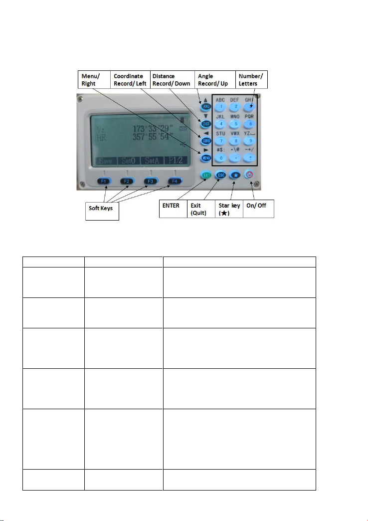
2.2 Functions of keyboards and the display of
information
Symbols on the keyboard
Symbol
Name
Function
ANG
Angle
Measurement
Enter Angle Mode
(Move the Cursor up or select the item
up under the other mode)
DIST
Distance
Measurement
Enter Distance Mode (Move the Cursor
up or select the item up under the other
mode)
CORD
Coordinate
Measurement
Enter Coordinate
(Move the Cursor left or page forward
and help to input characters under the
other mode)
MENU
Menu key
Enter Menu Page
(Move the Cursor right or page
backward and help to input characters
under the other mode)
ENT
Enter
Receive and save the data input in the
dialogue and end the dialogue. There is
also a function that open and close the
rectangular buzzer under the basic
measurement modes(ANG, DIST,
CORD, MENU)
ESC
Exit/ quit
End the dialogue box without saving
the input.

13
ON/ OFF
On/ Off
Control the power on/off
F1~F4
Soft Keys
The characters at the bottom line of the
display indicates the meaning of the
soft keys.
0~9
Number keys
Enter numbers or characters or choose
the menu
~ -
Special Symbols
Enter symbols, decimals and signs
★
Star key
It is used to operate the common
function of the instrument, and can
enter all the measuring interface .It
displays the dialog of the contrast,
lighting compensator , parameters of
distance measuring and file selecting.
Symbols on the display
Symbol
Indication
Vz
Zenith Mode
V0
The mode that the vertical is displayed as zero when the
telescope is level in normal .
Vh
Vertical angle Mode (it is 0°00′00″when the telescope is
level. The angle of elevation is positive and the angle of
depression is negative.)
V%
Slope Mode
HR
Horizontal angle (right angle). dHR meas the angle difference
of setting out.
HL
Horizontal angle (anticlockwise increment)
HD
Horizontal distance. dHD is to stake out horizontal distance
difference.
VD
Elevation difference. dVD is to stake out difference between
elevation differences.
SD
Slope distance. dSD is to stake out differences between slope
distances.
N
North coordinate. dN is to stake out differences between
north-coordinates.
E
East coordinate. dE is to stake out differences between
East-coordinates.
Z
Elevation coordinate. dZ is to stake out differences between
Z-coordinates
EDM(Electronic Distance Measurement) is in progress.
m
Unit in metres (metric units)
ft
Units in feet

14
fi
Units in feet and inches. Figures on the left of decimals
represent feet and those on the right represents feet in
percentile.
X
The magnitude of which is along the baseline in a point
projection measurement. The positive direction is from the
starting point to the terminal.
Y
The magnitude of which deviates from the base line
horizontally in a point projection measurement.
Z
Altitude of the target in a point projection measurement.
Inter Feet
International feet
Us Feet
American feet
MdHD
Maximum error of evaluated distance (used in resection
measurement)
Reference functions of common soft key
Soft key reference
Functions
B.S
(Backspace)Delete one last character on the left of the
inserter in the edited column.
Clear
Delete all typed in the edited column.
Enter
End up the input in the current edited column and the
inserter goes to the next column. If there‟s only one or no
edited column in the dialogue box, the soft key „Enter‟ is
also used to accept the input and exit the dialogue box.
Input
Go to Coordinate dialogue box and enter the coordinates
with keyboard
M.Pt
Retrieval coordinates of points from measured file
K.Pt (Known)
call coordinates of points from coordinate file
Search
List the points in the current coordinate file to provide
to select the number for you.
View
List out details of the current record
Info.
Displays the name, code and coordinate of the current
station and back-sight station.
Settings
Set the height of the instrument and the target
STA
Enter coordinates of the station where instrument is
placed.
BBS
Enter coordinates of the point where the target is.
Meas
Start rangefinders to measure distance
Save
Start rangefinders when being under the Coordinate and
Distance mode. Then save the result of this measurement
and name of point which is added by one automatically.
The result cannot be saved when the compensator is
over .(Tilt over)

15
Comp.
Display the inclination (tilt) of the vertical axis
Light
Turn on or off the backlight and the illuminating
brightness of reticle (at the same time).
Para.
Set the atmospheric parameters, prism constant and
signals.
2.3 Functional keys under the basic measuring mode
2.3.1Angle Mode(including 2 menu pages)
Page
Soft key
Reference
Function
1
F1
Save
Record the measured angle in
the selected file.
F2
Set0
Set the horizontal angle as 0°
F3
SetA
Set your desired horizontal
angle by inputting ,but the
angle should not be greater
than 360°
F4
P1/2
Display the second page of the
soft key functions
2
F1
Hold
Lock the horizontal angle
readings.
F2
L/R
Switch between HR
(horizontal right/ clockwise)
and HL (horizontal left/
anticlockwise) mode
F3
VA
Vertical Angle Mode (altitude
angle, Zenith, Horizontal „0‟,
slope)
F4
P2/2
Display the first page of the
soft key functions.

16
2.3.2 Distance Mode(including two menu pages)
Page
Soft key
Reference
Function
1
F1
Save
Start distance measurement and record
the measured data into the selected
files (measurement file„File(.MEA)‟
and coordinate file „File(.COO)‟are
selected in operating menu or by star
key).
F2
Meas
Start Distance Mode
F3
Mode
Switch between four distance
measurement mode (single accurate
measuring (sngl)/ repeated accurate
measuring (rept)/ continue accurate
measuring (cont)/ tracking (track))
F4
P1/2
Display the second page of the soft
key functions
2
F1
Offset
Start offset measurement (eccentric
measurement)
F2
Stake
Start staking out
F3
m/f/i
Switch distance units between meters,
feet, feet&inch.
F4
P2/2
Display the first page of the soft key
functions
Vz:90°0 0′00″
HR:180°00′00″
SD:S m
HD:
VD:
Save Meas Mode P1/2
Offset Stake m/f/i P2/2

17
2.3.3 Coordinate Mode(including three menu pages)
Page
Soft key
Reference
Function
1
F1
Save
Start coordinate measurement and record
the measured data into the selected files
(measurement file „File(.MEA)‟ or
coordinate file „File(.COO)‟ are selected
in surveying menu or by star key.
F2
Meas
Start coordinate measurement
F3
Mode
Switch between four distance
measurement mode [single accurate
measurement (sngl)/ repeated accurate
measuring (rept)/ continue measuring
(cont)/ tracking (track)]
F4
P1/3
Display the second page of the soft key
functions
2
F1
Setting
Set target height and instrument height
F2
BBS
Set coordinates of BBS (back-sight point)
and back-sight angle
F3
STA
Set coordinates for station
F4
P2/3
Display the third page of the soft key
functions
3
F1
Offset
Start offset measurement (eccentric
measurement)
F2
Stake
Stake out coordinates
F3
SetA
Set azimuth (the same as setting
horizontal angle under the Angle mode)
F4
P3/3
Display the first page of the soft key
functions

18
2.3.4 Explanation of Saving of data
If you have never selected the measurement file and your
first time to use the [Save] soft key , then a dialogue box of
„Select file‟ would appear to the screen. Mention that this is a
good chance for you to select all files that the instrument may use.
When finishing single measurement or repeated
measurement under each mode, a dialogue box „information‟
asking you to save the measured point, you may rename and code
the points or set target height. The key „ENT‟ will save the
coordinates into measurement files, and the key [★] save the
coordinates in the measurement file and coordinate file at the
same time (according to the mention of the display).
If you choose not to edit points, the points would be saved
with the present name, elevation and code .After saving, the name
of the point is added by one.
2.4 Star(★) Key Mode
Under the distance measurement interface, pressing the key
[★](star key) can lead to a page as shown below.
Settings from the star key(★) are as followed:
Adjust the contrast by pressing „▲‟ and „▼‟.
Adjust the he background light of the screen with „◄‟ and
„►‟.
Turn on or off the background light of the screen by pressing
Key „F1‟.
Turn on or off the display of compensation by pressing „F2‟.

19
Adjust reflector by pressing „►‟. Each time pressing the
key „►‟, the reflectance target is switched between prism
(Prism), non-prism (NP) and reflector board (RB).
Pressing key „F3‟ to switch on or off the visible laser beams.
Pressing the key „F4‟ to select „parameters‟, you can set
settings of prism const, PPM value and temperature and pressure.
If the instrument is equipped with temperature and pressure
sensor, pressing [F1] can automatically collect the current
temperature and pressure values and display the updated data
such as temperature, pressure, PPM,otherwise you can view the
signal strength.
The measurement parameters about distance measuring are
shown below: (After entering the temperature and pressure data,
the instrument would calculate PPM value automatically. If the
calculated PPM value is not favored, please reenter your expected
value.)
Temp= Temperature
Press= Atmospheric pressure
Prism c= Prism constant
PPM= PPM value
B.S= Backspace
Clear=clear up all typed in characters in the current column
Signal=Detect and display the intensity of laser signal.
Notice that the laser will be on automatically, even if you haven‟t
set it on. Take care that your sight are not in the scope of the laser
path .
Enter=Move inserter to the next column.
Press ENT to save the settings.
Temp:20.0 ℃
Press:1013.0 hpa
Prism C:0.0 mm
PPM :0.0 ppm
Signal:[ ]
B.S Clear Signal Enter

20
3. Initial Setup
3.1 On & Off
Press and hold the key „On/Off‟ ( the buzzer remain buzzer )
until the screen displays pictures as below. The instrument is now
switched on.
(The picture is for reference. Please in kind prevail!)
After self-checking is accomplished and the instrument
entersAngle Mode automatically (see details in 5. Angle Mode
for details)
Pressing power key will leads to a dialogue box as below.
Press [ENT] to turn off the instrument.
3.2 Set up the tilt correction of horizontal and
vertical angles
When the tilt (inclination) sensor is on, the instrument will
display the automatic correction value for the vertical angle
caused by not strictly level. In order to ensure the accuracy of the
angle measurement, try to use tilt sensor whose display can be
used to level the instrument better.
If displaying „Tilt over!‟ in the „Vz‟ column, it indicates that
the instrument beyond the range of the automatic compensation,
and it needs to be leveled by adjusting foot screw.
The ZTS-320 series Total Station can corrects the vertical
angle readings cased by the tilt of vertical axis in the X
direction.
It has two states of the compensator : on and off .
When the instrument is under unstable condition or in a
windy day , you should close the compensator ,because the
vertical is unstable .Only this ,can avoid the compensator
beyond the scope of work caused by the jitter and stop
measuring .You can turn off the compensator by the using star
key(★) functions.
Enter->Shut off
ESC->Quit
Quit after three seconds
This manual suits for next models
2
Table of contents
Other Hi-Target Measuring Instrument manuals


Popular Measuring Instrument manuals by other brands


TREND
TREND VJS/TG/JIG manual

Cosmos
Cosmos XP-3180 instruction manual

Connected Inventions
Connected Inventions AirWits CO2 user manual

YSI
YSI 550 DO Operation manual

Digital Watchdog
Digital Watchdog Blackjack Ai DW-BJAiARA2 quick start guide

Endress+Hauser
Endress+Hauser Cerabar S PMC71 operating instructions

horiba
horiba TPNA-500 instruction manual

Endress+Hauser
Endress+Hauser SS500 Hardware installation and maintenance manual

Renishaw
Renishaw SFP1 Installation and user guide

Konica Minolta
Konica Minolta bizhub C3100i user guide

eltherm
eltherm ELT-GP1 Documentation

PCB Piezotronics
PCB Piezotronics 3501B1260KG/010LN Installation and operating manual