HI GrainSaver U-Trough PS-001 Administrator Guide

U-Trough Power Sweep Installation
& Operator’s Manual
This manual applies to:
U-Trough:
Powersweep
Unload
Bin Diameters: 19’, 21’, 24’, 27’, 30’, 33’,
36’, 29’, 42’, 45’, 48’, 54’, 60’, 72’, 78’

CONTENTS
1. Introduction...............................................................................................................4
1.1. Intended Use..................................................................................................4
1.1.1 Misuse ................................................................................................4
2. Safety.........................................................................................................................5
2.1. Safety Alert Symbol and Signal Words...........................................................5
2.2. General Product Safety..................................................................................6
2.3. Rotating Flighting Safety ................................................................................6
2.4. Rotating Parts Safety .....................................................................................6
2.5. Work Area Safety ...........................................................................................6
2.6. Guards Safety ................................................................................................6
2.7. Bin Unloading Safety......................................................................................6
2.8. Bin Entry Safety .............................................................................................7
2.8.1 Roof Entry ...........................................................................................7
2.9. Bin Emergency Entry ..................................................................................... 7
2.10. Bin Entrapment ............................................................................................ 8
2.10.1 Flowing Grain.................................................................................... 8
2.10.2 Collapse of Bridged Grain.................................................................9
2.10.3 Collapse of a Vertical Wall of Grain ..................................................9
2.12. Drives and Lockout Safety ......................................................................... 11
2.12.1 Electric Motor Safety.......................................................................11
2.12.1 Hydraulic Motor Safety ..................................................................12
2.13. Personal Protective Equipment..................................................................12
2.14. Safety Equipment.......................................................................................13
2.15. Safety Decals.............................................................................................14
2.15.1 Decal Installation/Replacement .....................................................14
2.15.2 Safety Decal Locations and Details ...............................................14
3. Installation...............................................................................................................18
4. Operation.................................................................................................................20
4.1. Operation Safety .......................................................................................... 20
4.2. Bin Unload Overview ................................................................................... 20
4.3. Before Filling the Bin with Grain................................................................... 21
4.4. Operation of the Powersweep system ......................................................... 21
4.5. Emergency Shutdown.................................................................................. 22
4.6. Restarting with Full Underoor Auger .......................................................... 23
4.7. Cleanup........................................................................................................ 23
4.8. Extended Shutdown / End of Season .......................................................... 23
2

3
5. Maintenance............................................................................................................24
5.1. Maintenance Safety ..................................................................................... 24
5.2. Maintenance Schedule................................................................................. 24
5.3. Visually Inspect the Equipment .................................................................... 25
5.4. Inspect Hydraulic Hoses and Fittings........................................................... 25
5.5. Clean and Wash the Equipment................................................................... 25
5.6. Check the Gearbox Oil................................................................................. 26
5.7. Change the Gearbox Oil .............................................................................. 26
5.8. Tension the Belt Drive .................................................................................. 26
5.9. Align the Drive Belts ..................................................................................... 27
5.10. Replace the Drive Belts.............................................................................. 27
5.11. Replace the Sweep Drive Wheel................................................................ 27
5.12. Adjust the Bin Sweep Backboard ............................................................... 28
5.13. Removing the Underoor Auger Flighting .................................................. 29
6. Troubleshooting .....................................................................................................30
7. Specications .........................................................................................................34
7.1. Mechanical................................................................................................... 34
7.2. Power Requirements ................................................................................... 35

Thank you for purchasing a Grain Saver U-Trough Powersweep System. This equipment will allow safe and
ecient operation when you read and follow all of the instructions contained in this manual. With proper care,
your powersweep will provide you with many years of trouble-free operation.
Keep this manual handy for frequent reference and to review with new personnel. If any information in this
manual is not understood or if you need additional information, please contact your local distributor or dealer
for assistance.
This manual should be regarded as part of the equipment. Suppliers of both new and second-hand equipment
are advised to retain documentary evidence that this manual was provided with the equipment
The Powersweep is designed solely for use in the intended agricultural use as listed below. Use in any other
way is considered as contrary to the intended use. Compliance with and strict adherence to the conditions of
operation and maintenance as specied by the manufacturer, also constitute essential elements of the intend-
ed use.
The bin unload should be operated, maintained, serviced, and repaired only by persons who are familiar with
its particular characteristics and who are acquainted with the relevant safety procedures.
Accident prevention regulations and all other generally recognized regulations on occupational health and
safety must be observed at all times.
Any modications made to the bin unload may relieve the manufacturer of liability for any resulting damage or
injury.
Intended use for the powersweep:
• Handling grain, pulse crops, treated seeds, or other similar materials.
Use in any other way is considered as contrary to the intended use and is not covered by the warranty.
1. Introduction
Do not install/use the bin unload for/with:
• transferring material other than dry, free-owing food-grains.
• commercial or o-farm use.
1.1.1 Misuse
1.1. Intended Use
4

Indicates a hazardous situation that, if not avoided, may result in minor or moderate injury.
This safety alert symbol indicates important safety messages in this manual. When you see this
symbol, be alert to the possibility of injury or death, carefully read the message that follows, and
inform others.
Signal Words: Note the use of the signal words DANGER, WARNING, and CAUTION with the safety mes-
sages. The appropriate signal word for each message has been selected using the denitions below as a
guideline.
Indicates an imminently hazardous situation that, if not avoided, will result in serious injury or
death.
Indicates a hazardous situation that, if not avoided, could result in serious injury or death.
2.2. General Product Safety
YOU are responsible for the SAFE use and maintenance of your powersweep. YOU must ensure that you and
anyone else who is going to work around the powersweep understands all procedures and related SAFETY
information contained in this manual.
Remember, YOU are the key to safety. Good safety practices not only protect you, but also the people around
you. Make these practices a working part of your safety program. All accidents can be avoided.
• It is the powersweep owner, operator, and maintenance personnel's responsibility to read and understand
ALL safety instructions, safety decals, and manuals and follow them when operating, or maintaining the equip-
ment.
• Owners must give instructions and review the information initially and annually with all personnel before
allowing them to operate the powersweep. Untrained users/operators expose themselves and bystanders to
possible serious injury or death.
• The powersweep is not intended to be used by children.
• Use the bin unload for its intended purposes only.
• Do not modify the bin unload in any way without written permission from the manufacturer. Unauthorized
modication may impair the function and/or safety, and could aect the life of the bin unload. Any unauthorized
modication will void the warranty.
• Follow a health and safety program for your worksite. Contact your local occupational health and safety orga-
nization for information.
Indicates a potentially hazardous situation that, if not avoided, may result in property damage.
2. Safety
2.1. Safety Alert Symbol and Signal Words
5

2.3. Rotating Flighting Safety
• KEEP AWAY from rotating ighting.
• DO NOT remove or modify ighting guards, doors, or covers. Keep in
good working order. Have replaced if damaged.
• DO NOT operate the bin unload without all guards, doors, and covers in
place.
• NEVER touch the ighting. Use a stick or other tool to remove an ob-
struction or clean out.
• Shut o and lock out power to adjust, service, or clean.
2.4. Rotating Parts Safety
• Keep body, hair, and clothing away from rotating pulleys, belts, chains,
and sprockets.
• Do not operate with any guard removed or modied. Keep guards in good
working order.
• Shut o and remove key or lock out power source before inspecting or
servicing machine.
2.5. Work Area Safety
• Have another trained person nearby who can shut down the bin unload in case of accident.
• The work area should be kept clear of bystanders.
• Keep the work area clean and free of debris.
2.6. Guards Safety
• Keep guards in place and do not operate unless all guards are in place.
• Do not walk on, step on, or damage guards.
• Lock out power before removing a guard.
• Ensure all guards are replaced after performing maintenance.
2.7. Bin Unloading Safety
• Never enter a bin when loading or unloading.
• Unload only as described in the operation section of this manual.
• Lock the bin door (where equipped) and close/lock all other access doors when not in use.
6

2.8. Bin Entry Safety
The information in this section applies to entry through any access point.
Always try to work and solve problems without entering a bin.
If you must enter the bin, follow the safety information below to safely enter through
the roof or door:
• Stop the unloading process if the bin is being unloaded and lockout/tagout power before
entering the bin, refer to Lockout/Tagout Safety.
• Always wear a dust-ltering respirator when entering the bin. Grain dust and spores when
inhaled into the lungs can cause severe reactions leading to hospitalization in some cases.
Persistent exposure may cause “farmer’s lung,” which can eventually be fatal.
• Before working inside the bin, ventilate the area by opening the vent or by other equivalent
means to force air into the bin to prevent oxygen-decient atmosphere. Inadequate oxygen
is very harmful to your health and can cause death. Exposure to carbon dioxide can cause
drowsiness, headache and even death due to suocation. Test the atmosphere. If the car-
bon dioxide hazard cannot be reduced or eliminated or you cannot test the atmosphere, use
correctly tted and appropriate respirator.
• Never walk on grain to make it ow.
If you ignore the safety precautions above and enter the bin, you could die from being submerged.
2.8.1 Roof Entry
The information in this section applies to entry through the bin roof only.
• Never enter a bin from the roof if you don’t know its unloading history. Bridges of stored
material can form above a void space below, causing potential for entrapment.
• Have body harness tethered to a lifeline controlled by two others outside the bin. One
worker should be able to see inside worker through the inspection hatch. If there is an ac-
cident, one worker can focus on the victim while the other goes/calls for help.
• In the event that you are trapped in the bin as it is unloading, move as quickly as possible
toward the bin wall; keep yourself elevated above the material by walking on the owing
mass while staying as close as possible to the bin wall.
2.9. Bin Emergency Entry
In an emergency situation:
• Follow protocols set by your local occupational safety and health agency.
• If you need to rescue somebody inside the bin, call emergency responders and only attempt to rescue using
non-entry rescue procedure/equipment. Do not enter the bin unless you are trained for rescue, equipped and
relieved by another attendant.
7

2.10. Bin Entrapment
It takes more than 1000 lb (4.5kN) of force to remove someone buried below the surface.
The following sections cover common ways a person gets submerged or trapped:
2.10.1 Flowing Grain
• Grain ows in a funnel-shaped path when unloading. This vortex of grain behaves very much like a water
drain. Velocity increases as grain ows from the bin wall at the top of the grain mass into a small vertical col-
umn at the center of the bin.
• Flowing grain will not support the weight of a person. Submersion happens within seconds.
Figure 1. Suocation Hazards in Flowing Grain
2-3 SECONDS 4-5 SECONDS 22 SECONDS
AFTER THE UNLOADING
EQUIPMENT STARTS,
YOU HAVE 2-3 SECONDS
TO REACT
IN 4-5 SECONDS,
YOU ARE TRAPPED
AFTER 22 SECONDS, YOU
ARE COMPLETELY COVERED.
8

2.10.2 Collapse of Bridged Grain
• Grain can “bridge” across a bin, creating an empty air space below. A person can easily break through this
bridge and become trapped, risking suocation.
• To identify bridged grain, look for a funnel shape on the surface of the grain after having removed some of
the grain. If surface is undisturbed, the grain has bridged and formed a crust.
• Never walk on the grain crust. The crust rarely becomes strong enough to support the weight of a person.
• To remove bridge, try breaking the bridge from the inspection hatch or peak. Use a pole to hit the surface,
securing it with a rope in case it is dropped. Be aware that chunks of crusted grain can move down to the au-
ger and limit ow.
Figure 2. Suocation Hazards in Bridged Grain
2.10.3 Collapse of a Vertical Wall of Grain
• Vertical walls of grain are created when the bin is partially empty. Poking at the wall can make the grain ava-
lanche and submerge a person.
• Do not enter the bin to break down grain that has set up. Break grain mass from top of the bin outside.
9

Figure 3. Suocation Hazards from a Vertical Grain Wall
2.11. Combustible Dust
The powersweep has been designed for safe use in areas where hazards due to com-
bustible dust may potentially occur. Minimize the risk of a dust explosion by following
the preventive measures below.
Control the dust:
To control dust, consider as part of your work-site safety program to:
• Clean the grain to reduce the nes.
• Use equipment to minimize the breakage. For example, corn that is broken exposes the starch, the most
explosive element of the grain.
• Use a ltering system to capture the dust.
• Use an air system to reduce the dust.
• Spray edible mineral oil on the grain to reduce air-born dust when handling.
• Paint equipment that is in the interior of a facility with a coating that is slick, not allowing the dust to accumu-
late.
• Clean up dust deposits after operation of the equipment.
• Enclose all equipment to keep the dust from escaping.
Control the ignition source:
To prevent possible sources of ignition that could cause res or dust explosions:
• Do not smoke in any potentially hazardous area.
• Use only explosion-proof lights.
10
• Do not use anything around or inside the equipment that may produce a ame, such as a match, a lighter, or
anything that may produce a shower of sparks, such as a grinder or power saw, unless the air is free of dust
and all dust deposits have been removed from the work area, or the work area is wet such that dust cannot be
dispersed in the air and smoldering processes from sparks cannot develop. Use brush-less electrical tools and
explosion proof ash lights, for example.
• Follow the maintenance schedule to keep equipment operating at normal conditions. This will further help to
prevent the risk of components overheating or wearing out which may lead to explosion risks.
• Always purchase replacement parts from the manufacturer or authorized dealer/distributor. Original manufac-
turers parts are designed with explosion proof features where applicable
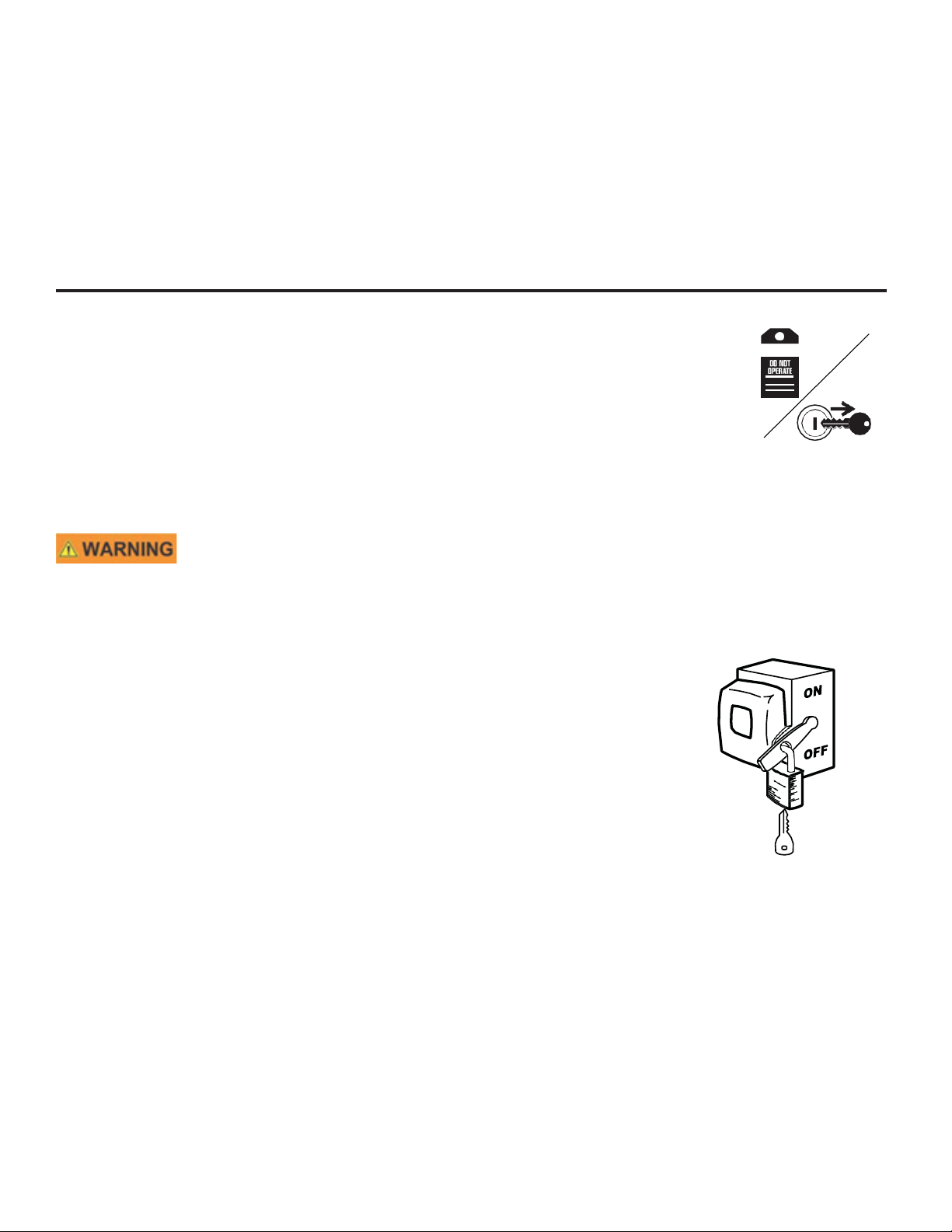
2.12. Drives and Lockout Safety
Inspect the power source(s) before using and know how to shut down in an emer-
gency. Whenever you service or adjust your equipment, make sure you shut down the
power source and follow lockout and tagout procedures to prevent inadvertent start-up
and hazardous energy release. Know the procedure(s) that applies to your equipment
from the following power source(s). Ensure that only 1 key exists for each assigned
lock, and that you are the only one that holds that key. Ensure that all personnel are
clear before turning on power to equipment.
WARNING
2.12.1 Electric Motor Safety
Power Source
• Electric motors and controls shall be installed and serviced by a qualied
electrician and must meet all local codes and standards.
• A magnetic starter should be used to protect your motor.
• You must have a manual reset button.
• Reset and motor starting controls must be located so that the operator has
full view of the entire operation.
• Locate main power disconnect switch within reach from ground level to
permit ready access in case of an emergency.
• Motor must be properly grounded.
• Guards must be in place and secure.
• Ensure electrical wiring and cords remain in good condition; replace if
necessary.
• Use a totally enclosed electric motor if operating in extremely dusty condi-
tions.
Lockout
• The main power disconnect switch should be in the locked position during
shutdown or whenever maintenance is performed.
• If reset is required, disconnect all power before resetting motor.
11

2.12.1 Hydraulic Motor Safety
Power Source
• Refer to the rules and regulations applicable to the power source operating your hydraulic
drive.
• Do not connect or disconnect hydraulic lines while system is under pressure.
• Keep all hydraulic lines away from moving parts and pinch points.
• Escaping hydraulic uid under pressure will cause serious injury if it penetrates the skin
surface (serious infection or toxic reaction can develop). See a doctor immediately if injured.
• Use metal or wood as a backstop when searching for hydraulic leaks and wear proper
hand and eye protection.
• Check all hydraulic components are tight and in good condition. Replace any worn, cut,
abraded, attened, or crimped hoses.
• Clean the connections before connecting to equipment.
• Do not attempt any makeshift repairs to the hydraulic ttings or hoses with tape, clamps,
or adhesive. The hydraulic system operates under extremely high pressure; such repairs
will fail suddenly and create a hazardous and unsafe condition.
Lockout
• Always place all hydraulic controls in neutral and relieve system pressure before discon-
necting or working on hydraulic system.
2.13. Personal Protective Equipment
The following Personal Protective Equipment (PPE) should be worn when operating or maintaining the
equipment.
Safety Glasses
• Wear safety glasses at all times to protect eyes from debris.
Work Gloves
• Wear work gloves to protect your hands from sharp and rough edges.
Steel-Toe Boots
• Wear steel-toe boots to protect feet from falling debris.
Coveralls
• Wear coveralls to protect skin.
Hard Hat
• Wear a hard hat to help protect your head.
12

Hearing Protection
• Wear ear protection to prevent hearing damage.
2.14. Safety Equipment
The following safety equipment should be kept on site:
Fire Extinguisher
• Provide a re extinguisher for use in case of an accident. Store in a highly visible and
accessible place.
First-Aid Kit
• Have a properly-stocked rst-aid kit available for use should the need arise, and know
how to use it.
Eyewash Kit
• Keep a portable eye wash kit available or make sure a permanent eyewash station is
available should the need arise to ush materials from the eyes. Review instructions for
use before working with the bin unload.
Salvage Container
• Keep a sealable salvage container on site, such as a spill containment pallet.
Absorbent Materials
• Keep granular absorbent materials on hand to clean up any chemical spills.
Aluminum Shovel and Broom
• Keep an aluminum shovel and broom for cleanup of spilled materials.
13

2.15. Safety Decals
• Keep safety decals clean and legible at all times.
• Replace safety decals that are missing or have become illegible.
• Replaced parts must display the same decal(s) as the original part.
• Replacement safety decals are available free of charge from your distributor, dealer, or factory as applicable.
2.15.1 Decal Installation/Replacement
1. Decal area must be clean and dry, with a temperature above 50°F (10°C).
2. Decide on the exact position before you remove the backing paper.
3. Align the decal over the specied area and carefully press the small portion with the exposed sticky backing
in place.
4. Slowly peel back the remaining paper and carefully smooth the remaining portion of the decal in place.
5. Small air pockets can be pierced with a pin and smoothed out using the sign backing paper.
Replicas of the safety decals that are attached to the bin unload and their messages are shown in the gure(s)
that follow. Safe operation and use of the bin unload requires that you familiarize yourself with the various
safety decals and the areas or particular functions that the decals apply to, as well as the safety precautions
that must be taken to avoid serious injury, death, or damage.
2.15.2 Safety Decal Locations and Details
14

Note:
Decal location same in incline discharge
Part Number Discription
PS-002
15

Part Number Discription
PS-001
PS-006
16

Part Number Discription
PS-003
PS-004
PS-005
17

3. Installation
Your Grain Saver™ Power Sweep System is completely assembled and is ready for in-
stallation in your new concrete foundation, or in your new existing conventional drying,
natural air drying or other style aeration / drying system.
To install Power Sweep System in a concrete foundation:
A. The Splined Gearbox Sweep output shaft is to be the center of the concrete foundation.
B. Set the concrete forms, “stake” the tube in place using the leveling brackets provided on
the Center Hopper to prevent “slip” and “oat”.
C. Check control rod sleeves to be certain that they were not bent in shipping or handling.
This could cause diculty in opening the wells. Straighten if necessary with a pry bar.
D. The discharge end of the tube must be installed at least 1” lower than the intake end to
prevent water build-up in the tube.
E. Pour the concrete foundations to the bin manufacturer’s specications and let “cure”.
F. Install the sweep assembly with the one bolt “keeper” over the splined shaft.
G. Adjust the sweep backboard to the length by loosening the 4 bolts and rotating the wheel
so the sweep telescopes in or out to the desired location. Tighten the bolts. Sweep should
also be adjusted on both the center and wheel end to ensure proper movement and opera-
tion. Make sure the sweep is not touching the bin oor at any point around the bin.
H. Install Powerhead drive by inserting powerhead drive screw into unload screw and fasten
them with the 2 provided bolts and tighten them. Then tighten the ange clamps on pow-
erhead drive to ange on unload tube or u-trough. Adjust the unload screw on the spline of
the center gearbox by loosening the insert bearing on the powerhead and sliding the unload
screw and connected powerhead screw in or out so it is connected securely on the spline of
the center gearbox. When properly set, There should be approximitely 7/8” to 1” of spline
showing from the gearbox plate to the unload screw spine.
I. Install sweep safety stop on the inside of the bin wall right behind where the sweep will be
parked when lling the bin, the sweep should be parked right over the sumps.
18

To Install Power Sweep System in Drying, Aeration or Full Floor Systems:
A. Locate the area where the tube is to exit the bin wall. Using the rodent cover as a tem-
plate cut the hole just large enough to allow for the tube and ange to pass through with mini-
mal clearance. Be sure to allow for the handles and handle cover as well.
B. Align the splined gearbox output shaft with the center of the bin.
C. Check control rod sleeves to be certain that they were not bent in shipping or handling.
This could cause diculty in opening the wells. Straighten if necessary with a pry bar.
D. Level the tube using the leveling brackets provided. Make sure that there is a 1” decline
in the tube towards the discharge end or drill a 1/8” diameter hole in the center intake hopper
bottom to allow for drainage.
E. Install the Drying / Aeration oor to the manufacturer’s specications. Seal the area in the
oor that was cut to t around the hoppers with Grain Saver™ Hopper Flanges. Use self-drill-
ing screws to attach this to the hopper
F. Install the Grain Saver™ Bin Wall Plate over the tube and opening in the bin wall and at-
tach with bolts or screws. The top half overlaps the bottom half by 1/2” to allow for proper
watershed. Caulk any cracks or openings and ll corrugations with a good quality silicone or
butyl based sealant.
G. Install the sweep assembly with the one bolt “keeper” over the splined shaft.
H. Adjust the sweep backboard to the desired length by loosening the 4 bolts and rotating the
wheel so the sweep telescopes in or out to the desired length. Tighten the bolts. Sweep
should also be adjusted on both the center and wheel end to ensure proper movement and
operation. Make sure the sweep is not touching the bin oor at any point around the bin.
I. Install Powerhead drive by inserting powerhead drive screw into unload screw and fasten
them with the 2 provided bolts and tighten them. Then tighten the ange clamps on pow-
erhead drive to ange on unload tube or u-trough. Adjust the unload screw on the spline of
the center gearbox by loosening the insert bearing on the powerhead and sliding the unload
screw and connected powerhead screw in or out so it is connected securely on the spline of
the center gearbox. When properly set, There should be approximitely 7/8” to 1” of spline
showing from the gearbox plate to the unload screw spine.
J. Install sweep safety stop on the inside of the bin wall right behind where the sweep will be
parked when lling the bin, the sweep should be parked right over the sumps.
Note: If any warning or safety decals become lost or damaged in any manner, please contact
us for free replacements. and the perforated oor. Caulk any cracks or openings with a good
quality silicone or butyl based sealant.
19

4. Operation
Before continuing, ensure you have completely read and understood this manual’s Safety
section, in addition to the safety information in the section(s) below.
4.1. Operation Safety
• Keep away from rotating and moving parts, including the auger ighting, drive components,
shafts, and bearings.
• Do not enter the grain bin while the bin unload is operating.
• Always operate with guards, covers, and shields in place.
• Have another trained person nearby who can shut down the equipment in case of accident.
• Keep the work area clear of bystanders.
• Keep the work area clean and free of debris.
• Ensure maintenance has been performed and is up to date.
Refer to your bin operation manual for specic operating and safety information for your bin.
4.2. Bin Unload Overview
The bin unload system operates by rst opening the center sump to remove 70-80% of grain by gravity (see
step 1 below). Next, the intermediate sumps are opened when the center sump runs empty to free the sweep
(see step 2 below). Next, the bin sweep is operated to remove the remaining 20-30% of grain (see step 3 be-
low). Lastly, the sweep is parked over the sumps for the bin to be relled again.
Open center hop-
per. Unload until
gravity ow stops.
Open intermediate
hopper and unload
until gravity ow
stops.
Stop equipment
and engage clutch
on bin sweep.
Remove remaining
grain.
Return sweep to
position over inter-
mediate hoppers
and bin is ready to
be relled.
To prevent serious injury or death from bin collapse,
the center sump must be open rst to empty bin.
Make certain there are adequate vents installed on the bin to prevent a vacuum from
forming in the upper portion of the bin during unloading. The pressures on the roof
caused by such a vacuum could damage or cause structural failure to the bin roof.
20
This manual suits for next models
4
Table of contents


