Hiber Hiberband Via User manual

Hiberband Via: Quick Start Guide
In this Quick Start Guide you will find everything you need to get set
up, apart from a drink to celebrate a successful installation.

2

3
6QUICK START GUIDE OVERVIEW.1
10
PREPARING FOR THE BGAN TERMINAL INSTALLATION.2
STEP BY STEP INSTALLATION.
Step 01: identifying the installation location on site.
Step 02: installing the equipment.
Step 03: connecting the cables and antennas.
Step 04: powering up the Via gateway.
Step 05: pointing the BGAN terminal.
Step 06: connecting to the Hiberband Via gateway Wi-Fi hotspot.
Step 07: verifying if the satellite connection is established.
Table 01: BGAN LED status indicator table.
Table 02: Via gateway LED status indicator table.
Appendix 01: installation diagram.
143
34
32
30
28
24
20
16
15
36
44
SAFETY GUIDE AND WARRANTY.5
39
PRODUCT INFORMATION.4
38

4
Welcome to your
Hiberband Via gateway.
Thanks for ordering your Hiberband Via gateway. It really is the easiest and most affordable way to create a
private LoRaWAN network in remote locations. The Hiberband Via gateway connects to the internet via the
Inmarsat satellite network, and can be powered by a renewable energy source such as solar. Making it perfect
for locations where conventional power and internet connectivity are not available.

5
A
C
B
The Quick Start Guide takes you through a typical Via gateway
installation, step by step. If you need more detailed installation
instructions, please visit hiber.global/support/via
To help you out, we’ve included an image of a complete installation
of the Hiberband Via gateway (fig.01) and an installation diagram
(Appendix01, page 38).
For more information on installing your Via gateway in the field,
please see the Hiberband Via: Field installation checklist.
B
C
A
Field LoRa antenna
BGAN terminal
Hiberband Via gateway
FIG. 01

6
SECTION 01
Quick Start Guide overview.
Before you start installation please check you have everything you need in the boxes A, B & C. The
illustrations below show the contents of the boxes. Please note, the LoRa field antenna (Box B) is in
some cases shipped separately by a local supplier instead of Hiber.

7
A03
A08
A07
A02
A05
A01
A04
A09
A10
A06
SECTION 01
A01
A02
A03
A04
A05
A06
A07
A08
A09
A10
Hiberband Via gateway
Power cable with MC4 connectors
AC/DC convertor for outdoor usage with
MC4 connectors
Wall mount AC/DC adapter with MC4
connectors
4x metal mounting straps
Wi-Fi antenna
LoRa antenna cable
Lightning protector
Quick start LoRa antenna (length: ~20cm)
Ethernet cable
BOX A

8
SECTION 01
B01
B02
Field LoRa antenna (length: ~160cm)
Field LoRa antenna clamps
BOX B*
B02
B01
The box components might differ slightly as the
frequency used for LoRa communication differs from
country to country.
*

9
SECTION 01
C01
C02
C03
C04
C05
Cobham Explorer 540 terminal
Ethernet cable
Power cable
Pole mount kit
H5 5mm Hex/Allen key
BOX C
C01
C03 C02
Required installation tools:
(Electric) screwdriver set
Wrench set
Power drill (optional)
Screws and plugs (optional)
C04
C05

10
Preparing for the
BGAN terminal installation.
To successfully complete the steps described in this section an internet connection
is required. Which might not be available in remote locations. So please make sure to
complete all steps described in this section before installing the Via gateway and BGAN
terminal in the field.
SECTION 02
Do not open the BGAN terminal enclosure without consulting Hiber. The enclosure has
been waterproofed and opening it will compromise the waterproofing.

11
A Cobham Explorer 540 terminal is used to connect the Hiberband Via gateway to the Inmarsat satellite
network. Inmarsat satellites are geostationary satellites, i.e. when looking from Earth into space the satellites are
at a fixed point in the sky at all times. In order to establish a connection, the BGAN terminal needs to be pointed
directly at the satellite.
The direction you need to point the BGAN terminal, differs per location. To identify the position of the
geostationary satellite on the intended installation location, you will need to know 2 variables: Azimuth and
Elevation (see fig. 02).
GEOSTATIONARY SATELLITE CONNECTION.
Elevation tells you how high up in the sky to look
and ranges from 0° (at the horizon) to 90° (directly
overhead).
Azimuth tells you what direction to face and ranges
from 0° to 360°, it starts with North at 0°.
ELEVATION
AZIMUTH
NORTH
SECTION 02
FIG. 02

12
FINDING THE AZIMUTH AND ELEVATION ANGLE FOR YOUR INSTALLATION LOCATION.
Visit the website www.dishpointer.com and enter the installation location address or latitude
and longitude.
1.
It’s really important to record the Azimuth and Elevation for your specific location, as you cannot
complete installing the BGAN terminal in the field without it.
5.
Now you have everything needed to complete the installation in the field. Except, maybe, a flask of coffee!
If we take Amsterdam in the Netherlands as an example, the correct satellite would be 24.8E.
ALPHASAT. When you searching using this example the information gives the following values:
Azimuth (true): 155.4°, Elevation: 27.3°.
4.
There are four Inmarsat satellites covering the globe. Fig. 03 shows you the areas that they cover
and the name of the satellite to choose.
2.
From the dropdown menu, choose the satellite which you identified in step 2 and click ‘Search’.3.
SECTION 02

13
90°
80°
70°
60°
50°
40°
30°
20°
10°
0°
10°
20°
30°
40°
50°
60°
70°
80°
90°
180° 160° 140° 120° 100° 80° 40° 0° 40° 80°60° 20° 20° 60° 100° 120° 140° 160° 180°
143.5E INMARSAT 4-F197.6W INMARSAT 4-F3 24.8E ALPHASAT 63.9E INMARSAT 4-F2
FIG. 03
SECTION 02

14
Step by step installation.
We know you can’t wait to get started. But please refer to the Hiberband Via: Field installation checklist
before starting with the installation. As not setting up the Via in the right location can really affect performance.
SECTION 03

15
At the installation site, identify the right structure and location on which to install the Hiberband Via gateway
and BGAN terminal.*
STEP 01: IDENTIFYING THE INSTALLATION LOCATION ON SITE.
FIG. 04
Use a compass to determine in which
approximate direction the satellite is using the
Azimuth you noted in Section 2.
To establish a connection with the satellite
ensure a clear line of sight between the satellite
antenna and the sky. There should be no
obstructions, e.g a tree, building, pole.
See fig. 04.
Please note: The standard cables provided with the BGAN satellite terminal to connect to the Hiberband Via
gateway are 2 meters long. If you plan to install the BGAN terminal further away from the Via gateway, please
contact support@hiber.global.
*
SECTION 03

16
STEP 02.1: INSTALLING THE HIBERBAND VIA GATEWAY
On the Via gateway, unscrew
the bolt at the bottom of the
mounting bracket and remove
the holder out of the mounting
bracket.
1. Pole or rail installation.
Fix the holder on a pole or
rail, using the metal mounting
straps A05 (fig. 05.2).
2. Wall installation.
Fix the holder on a wall, using
wall plugs and screws – not
included. (fig. 05.3).
2.
FIG. 05.1 FIG. 05.2 FIG. 05.3
SECTION 03

17
Hang the Via gateway on the
holder.
3. Secure the holder on the
mounting bracket using the
bolt removed in step 1.
4. Make sure you install the Via
gateway with the connectors
facing down (fig. 05.6).
5.
FIG. 05.4 FIG. 05.5 FIG. 05.6
SECTION 03

18
We provide two LoRa antennas with the Via gateway:
STEP 02.2: INSTALLING THE LORA ANTENNA.
Field LoRa antenna B01: for optimal LoRa
coverage when performing a field installation,
install the Field LoRa antenna B01 on a pole or
rail using the LoRa antenna clamps B02 (fig. 06).
Quick Start LoRa antenna A09: this antenna is
perfect for testing purposes (e.g. to test the
Via gateway before a field installation) as it
can be screwed directly onto the Via gateway
as described in step 3.1, no mounting required.
Please note that this antenna offers limited
LoRa coverage and is not suitable for a field
installation.
FIG. 06
SECTION 03

19
SECTION 03
FIG. 07.1
STEP 02.3: INSTALLING THE BGAN TERMINAL.
Attach the mounting bracket C04 to the BGAN terminal C01
using the included hex key C05 and the 4 screws.
1.
Remount the two remaining long screws. Do not tighten the
screws completely until you have completed the pointing process
in Step 5 (fig. 07.2).
4.
Unscrew two of the long screws from the mounting kit to leave
one side open for the pole (fig. 07.1).
2.
Wrap the mounting kit with the attached BGAN terminal around
the pole.
3.
FIG. 07.2
C04
C01

20
The Via gateway has a series of connectors on its base and the BGAN terminal has 2 cables
coming out of its enclosure.
Please connect the cables and antennas to the correct Hiberband Via gateway connectors
as explained below.
STEP 03: CONNECTING THE CABLES AND ANTENNAS.
SECTION 03
Table of contents
Popular Gateway manuals by other brands
Dell
Dell Edge Gateway 3003 Installation and operation manual
SST Automation
SST Automation GT200-HT-RS user manual
HumanTechnik
HumanTechnik Signolux Operation instructions

EdgeWave
EdgeWave iPrism Hardware guide

STIEBEL ELTRON
STIEBEL ELTRON ISG quick start guide
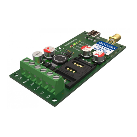
SECURECOM
SECURECOM SC-GSM Installing and programming Manual
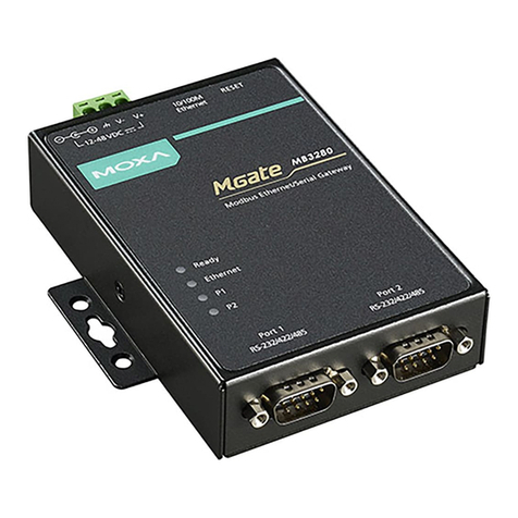
Moxa Technologies
Moxa Technologies MGate MB3280 Quick installation guide
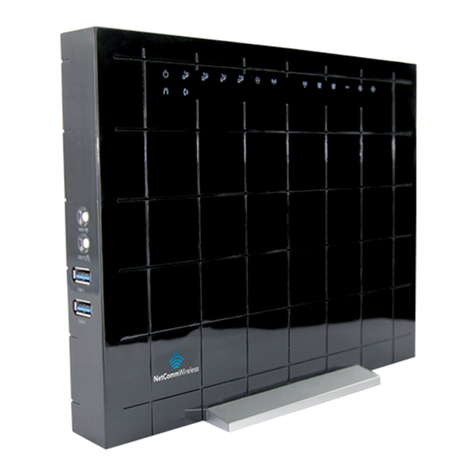
NetComm
NetComm FIBRE NF1ADV quick start guide
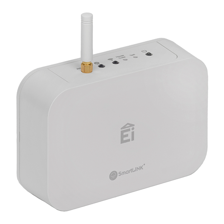
Ei Electronics
Ei Electronics SmartLINK Ei1000G installation manual

Genexis
Genexis Platinum-6820 installation guide
ProSoft
ProSoft PLX51-DNPS quick start guide
EUCHNER
EUCHNER AS-i 3.0 installation instructions
