14 MULTI FUNCTIONAL CCTV TESTER 15
MULTI FUNCTIONAL CCTV TESTER
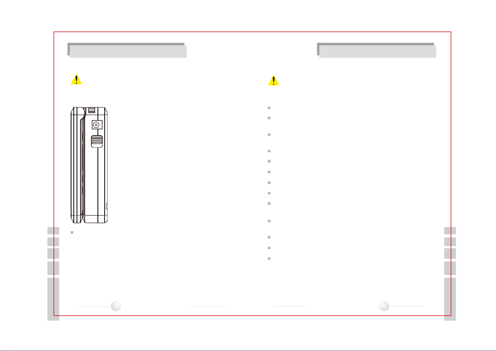
PRODUCT INTRODUCTION
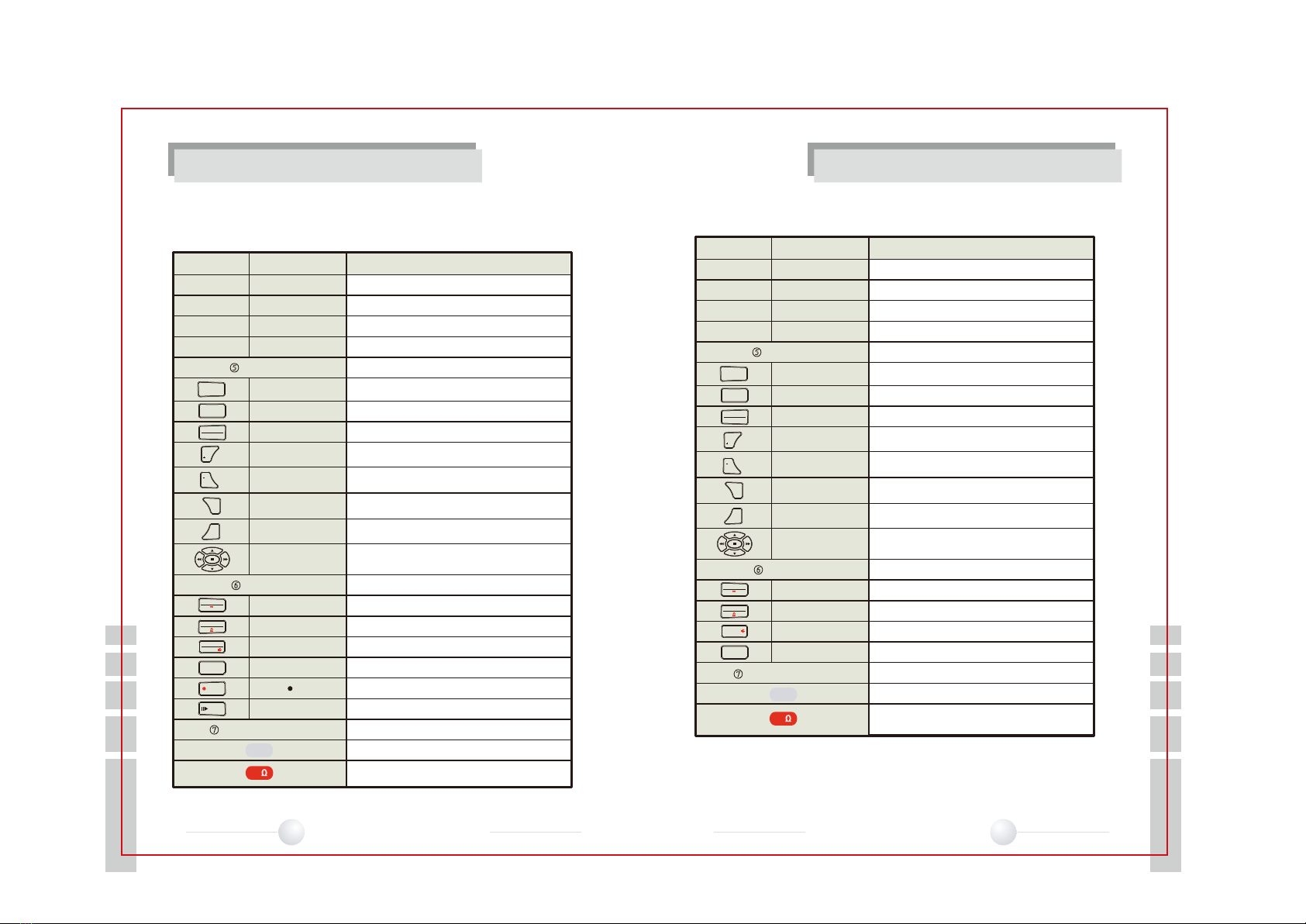
Part Name Function
LCD TFT LCD
POWER Red LED is on when the OSD POWER is on
Data Transmitting LED Red LED is on when Data is Transmitted
Data Receiving LED Red LED is on when Data is Received
Key Button
Key Button For Controlling External Devices i.e. Rapport III
MODE Button Used to Change Setup
SET Button OSD Selection
OSD Button It toggles OSD & POWER on/off
FAR Button Adjusts PTZ Focus (Far Direction) &
Increases Video Image Brightness
NEAR Button Adjusts PTZ Focus (Near Direction) &
Decreases Video Image Brightness
TELE Button Zooms PTZ (Zoom In) &
Increases Video Image Contrast
WIDE Button Zooms PTZ (Zoom Out) &
Decreases Video Image Contrast
Shift Setup Button Moves PTZ Up, Down, Right, Left &
Also Used for Menu Functions
METER
Voltage Button Measures Voltage
Resistance Button Measures Resistance
Setup Change Button Changes setup Between AC & DC, Resistance/continuity Test
Record Video (Rapport
III-
PRO)
Image data list for SD card (Rapport
III
-PRO)
Playback Recoded Video (Rapport
III
-PRO)
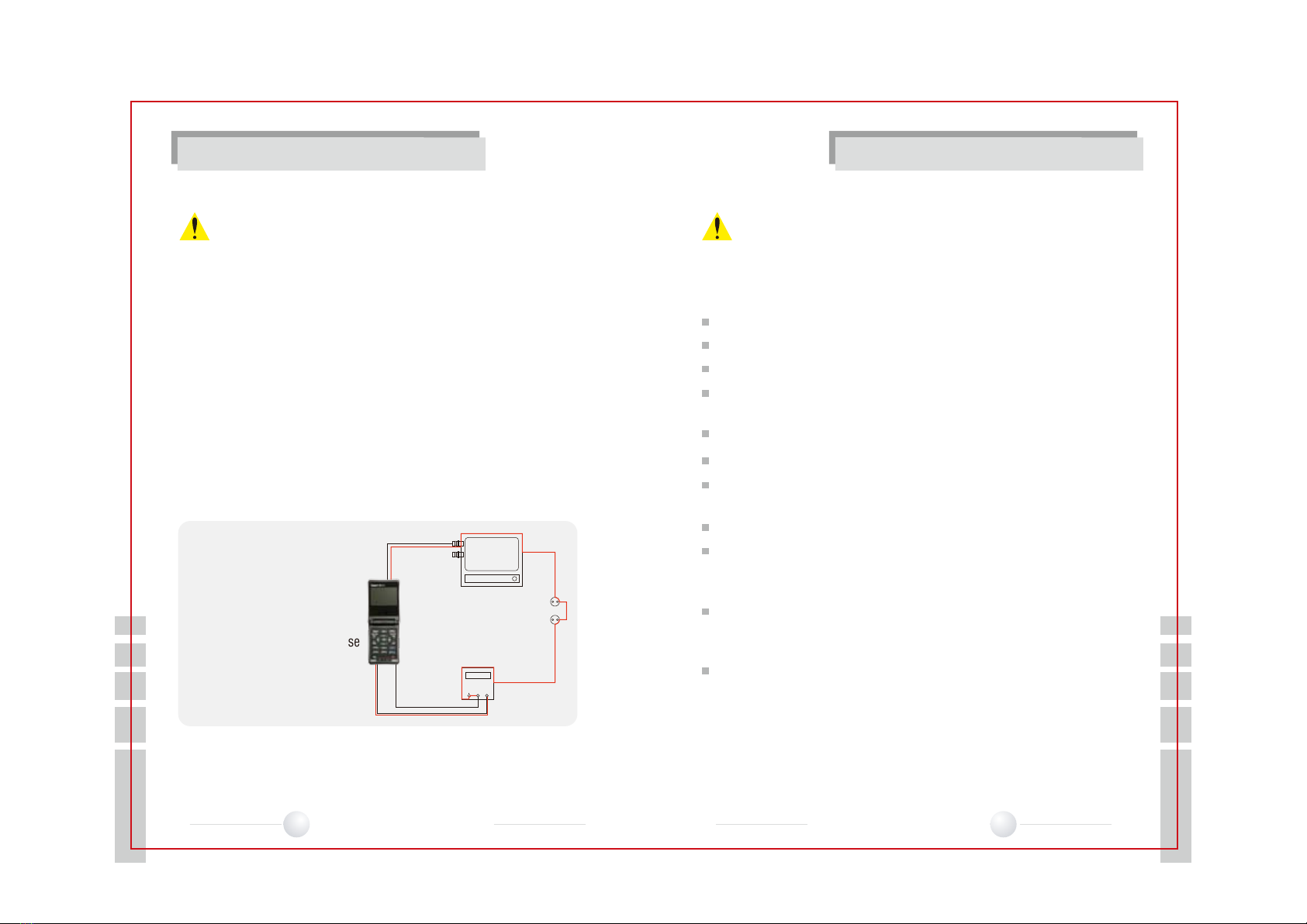
Test Lead Connection Positions
Position of Black Test Lead, Common Ground(-ve)
Position of Red test Lead for Measuring
Voltage & Resistance(+ve)
①
②
③
④
⑥
⑤
⑦
FILE
REC
PLAY
Test Lead Connection
FILE
MODE
SET
TELE
WIDE
OSD
PWR
CLEAR
AC DC
/ /
V
OPEN
CLOSE
REC
PLAY
COM
V/
PRODUCT INTRODUCTION
Rapport III-Pro
Part Name Function
LCD TFT LCD
POWER Red LED is on when the OSD POWER is on
Data Transmitting LED Red LED is on when Data is Transmitted
Data Receiving LED Red LED is on when Data is Received
Key Button
Key Button For Controlling External Devices i.e. Rapport
III
MODE Button Used to Change Setup
SET Button OSD Selection
OSD Button It toggles OSD & POWER on/off
FAR Button Adjusts PTZ Focus (Far Direction) &
Increases Video Image Brightness
NEAR Button Adjusts PTZ Focus (Near Direction) &
Decreases Video Image Brightness
TELE Button Zooms PTZ (Zoom In) &
Increases Video Image Contrast
WIDE Button Zooms PTZ (Zoom Out) &
Decreases Video Image Contrast
Shift Setup Button Moves PTZ Up, Down, Right, Left &
Also Used for Menu Functions
METER
Voltage Button Measures Voltage
Resistance Button Measures Resistance
Setup Change Button Changes setup Between AC & DC, Resistance/continuity Test
Measures Video Level
Test Lead Connection Positions
Position of Black Test Lead, Common Ground(-ve)
Position of Red test Lead for Measuring
Voltage & Resistance(+ve)
①
②
③
④
⑥
⑤
⑦
IRE
Test Lead Connection
IRE
MODE
SET
TELE
WIDE
OSD
PWR
AC DC
/ /
V
OPEN
CLOSE
COM
V/
Rapport III
NEAR
FAR
10
10
NEAR
FAR
10
10
Test Equipment Depot - 800.517.8431 - 99 Washington Street Melrose, MA 02176
TestEquipmentDepot.com