4900 Westside Avenue, North Bergen, New Jersey 07047
Tel: [201] 223-0050 Fax: [201] 223-0950
Hickory Industries, Inc.
N/5.7G-9/01
Page 3 of 25
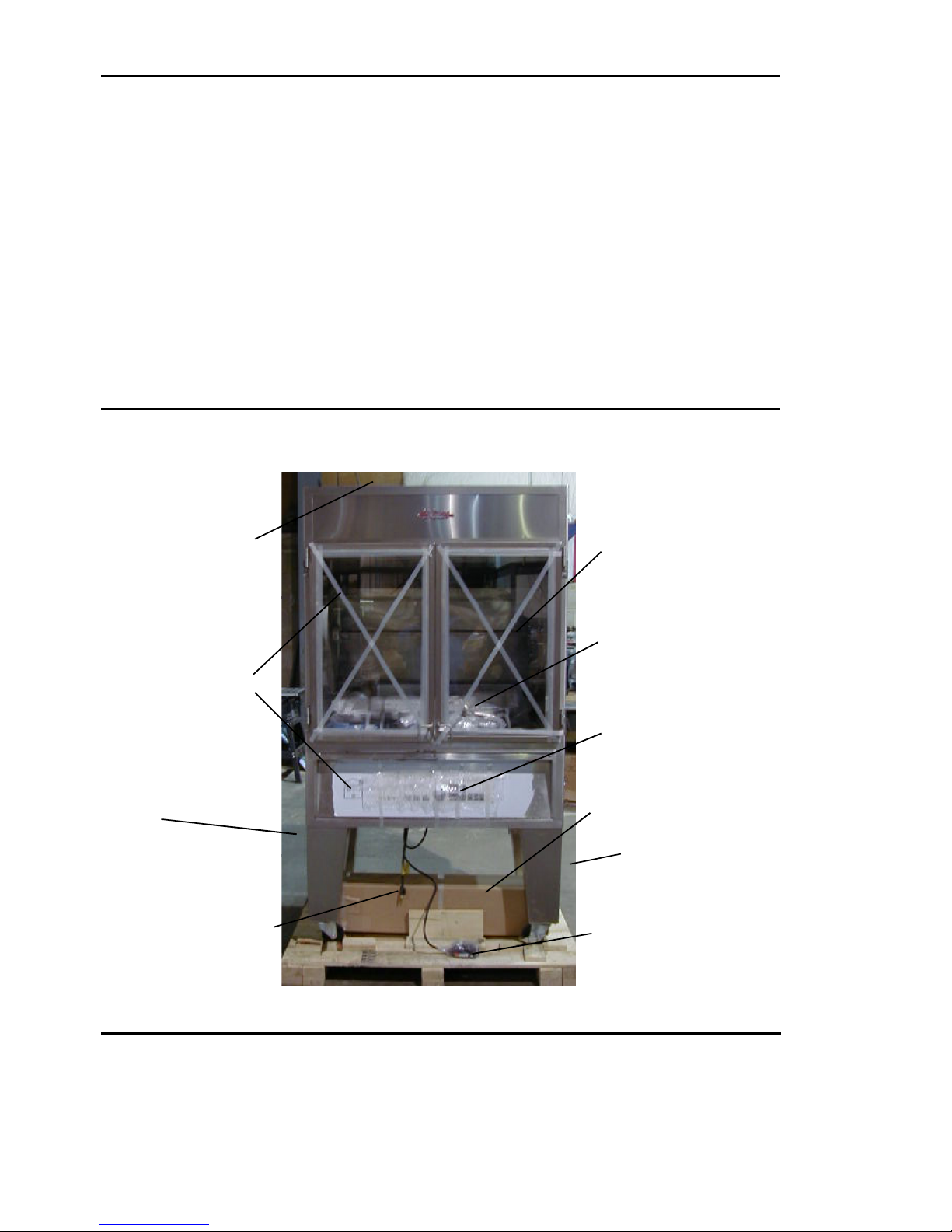
Installation Tips
a. When installingtheseunits,itisimportantto comply with the most recently established
rulesandregulationsas deemed pertinent by thelocalandnational electrical, gas, ventilation,
sanitation,andfire codes. These units are classifiedbyUnderwriters Laboratories, Inc. as
Gas-FiredFoodService Equipment in accordancewith American National StandardsInstitute
ANSIZ83.11b-1991, Gas Food Service Equipment - Ranges andUnit Boilers.
b. Thesegasunitsmaynotbe directly connected to a gas flueorexhaust. However, the
unitsmayonlybeoperatedinconjunctionwithacanopytypeexhausthood.
c. Theroomwhere the units arebeinginstalled must be ventilatedinaccordance to the
validcodes and regulations.
d. Theunitsaretobe installed securely and horizontally. The unitsmay be installed on
combustiblefloors.
e. Theminimum clearance to the rear or side walls must be 3 inches. It isalso important
toinsure that the bottomof the units iskept clear so thatproper ventilation or airexchange can
occur.
f. Normally,theunitswillbesent to the operator already setupfortheparticulartypeof
gasavailable at their location. However,unless otherwise specified, theunits will be setup for
naturalgasuse. Before installing and usingtheunits for the firsttime,it is important tomake
surethat the gastype and pressure indicated on the data plate matches the type of gas avail-
ablein the location. Should thisnot be the case,it is imperative tochange or convertthe units
tothe needed gastype.
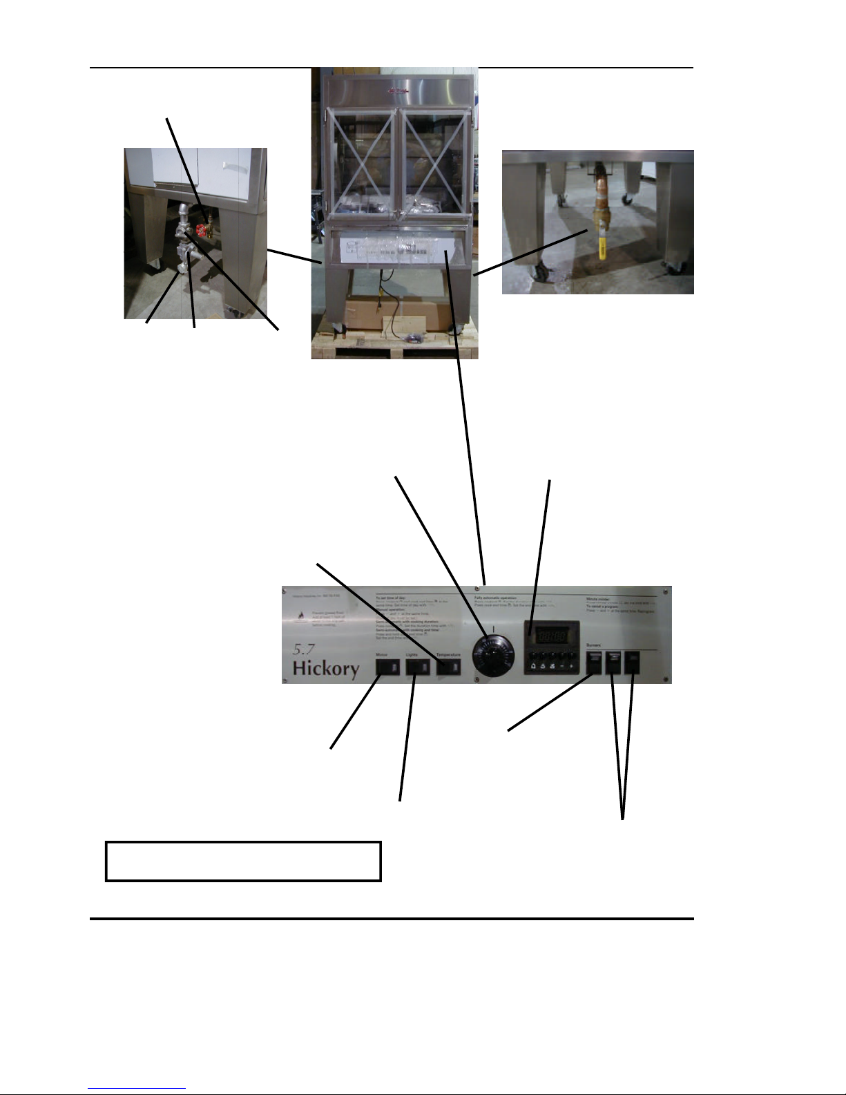
g. Theunitsmustbefittedwiththemanualshut-offgascock(valve)suppliedwiththe
machine. Thismanualvalve is needed to shutoffthe gas to the machineduringmaintenance
work,repairs, pressure testingand if the unit needs to be disconnectedfor any reason. DO
NOT REMOVE otherwise warranty will be voided.
h. Agas regulator is alsosupplied with the machine. This component is neededso that
theappropriategas pressure can beset and insure anoptimum operation of theunit. DO
NOT REMOVE otherwise warranty will be voided.
i. Wheninstallingthis unit with agasquick disconnect, a tetheringdevicemust be used.
j. Depending on local codes or if deemed necessary, a gas filter may also be required.
k. Doconnect the unit toa 1" gasline. Connecting the unit to a lesser linecan reduce the
unitseffectiveness or cause improperoperation.