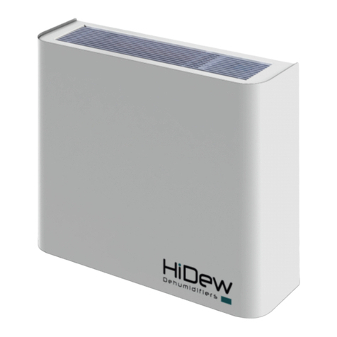
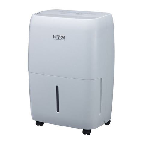
HiDew DDS Service manual

www.hidew.it
info@hidew.it
INSTALLATION, USE AND
MAINTENANCE MANUAL
DDS Dehumidifier for exposed installation swimming pools
DCS Piped dehumidifier for technical compartment
installation swimming pools
DVS Vertical dehumidifier for exposed installation swimming
pools
DOS Horizontal dehumidifier for false ceiling installation
swimming pools

rev08- Installation, use and maintenance manual
DDS-DCS-DVS-DOS - Dehumidifiers for small swimming pools
2 - 60
The reproduction, even partial, of this document without the written permission of HiDew S.r.l. is prohibited.

Installation, use and maintenance manual –rev08
DDS-DCS-DVS-DOS - Dehumidifiers for small swimming pools
3 - 60
DDS –DCS –DVS - DOS
Dehumidifiers for small swimming pools
READ THIS MANUAL CAREFULLY BEFORE USING THE UNIT
Dear Customer,
thank you for choosing our product. We are pleased to provide you with this manual to obtain the best use of
our product, and for maximum comfort and increased safety.
Please read the recommendations described in the following pages carefully and make the manual available
to the personnel who will be responsible for managing and maintaining the unit.
Our company is at your disposal for any questions you may have both during the unit start-up phase or at any
other time.
Our Technical Department is at your disposal for any assistance and spare parts you may require, especially
during routine or extraordinary maintenance.
Please find our contact details below for a more rapid service:
Hidew s.r.l.
Operational headquarters:
Via dell’artigianato, 1 - 35020 - San Pietro Viminario (PD) - Italy
Tel +39 049/9588510
Registered office:
Viale Spagna, 31/33 - 35020 - Tribano (PD) - Italy
Tel +39 049/9588511 - Fax +39 049/9588522
EEE Register: IT18080000010604

rev08- Installation, use and maintenance manual
DDS-DCS-DVS-DOS - Dehumidifiers for small swimming pools
4 - 60
SUMMARY
1PREAMBLE ....................................................................................................................................................................... 5
1.1 RESPONSIBILITY ..................................................................................................................................................................... 6
1.2 SERVICE RULES....................................................................................................................................................................... 6
1.3 INTENDED USE....................................................................................................................................................................... 7
1.4 RESIDUAL RISK AREAS............................................................................................................................................................ 7
1.5 INTERVENTION AND MAINTENANCE..................................................................................................................................... 8
1.6 GENERAL SAFETY RULES ........................................................................................................................................................ 9
2PRODUCT DESCRIPTION ................................................................................................................................................. 10
2.1 COMPONENTS ..................................................................................................................................................................... 10
2.2 SERIES.................................................................................................................................................................................. 11
2.3 OPERATING LIMITS .............................................................................................................................................................. 12
2.4 DIMENSIONS ....................................................................................................................................................................... 12
2.5 FUNCTIONS.......................................................................................................................................................................... 13
2.6 OPTIONS .............................................................................................................................................................................. 13
2.7 INSTALLATION ..................................................................................................................................................................... 15
2.8 ELECTRIC CIRCUITS .............................................................................................................................................................. 15
3CONTROL........................................................................................................................................................................ 16
3.1 BUTTONS ............................................................................................................................................................................. 16
3.2 MAIN PAGE.......................................................................................................................................................................... 17
3.3 USER MENU ......................................................................................................................................................................... 17
3.4 ALARMS MENU.................................................................................................................................................................... 20
3.5 UNIT STATUS MENU ............................................................................................................................................................ 20
3.6 HOUR BAND MENU ............................................................................................................................................................. 21
3.7 OTHER PAGES ...................................................................................................................................................................... 22
4TECHNICAL DATA............................................................................................................................................................ 23
4.1 DDS -DCS TECHNICAL DATA TABLES .................................................................................................................................... 23
4.2 DVS TECHNICAL DATA TABLES ............................................................................................................................................. 25
4.3 DOS TECHNICAL DATA TABLES............................................................................................................................................. 26
4.4 PERFORMANCE CURVES ...................................................................................................................................................... 27
4.5 FUNCTIONAL DIAGRAM....................................................................................................................................................... 29
5AFTER-SALES .................................................................................................................................................................. 30
5.1 TROUBLESHOOTING ............................................................................................................................................................ 30
5.2 ORDINARY MAINTENANCE .................................................................................................................................................. 31
5.3 EXTRAORDINARY MAINTENANCE........................................................................................................................................ 33
6DISMANTLING OF THE UNIT ........................................................................................................................................... 35
6.1 AMBIENT PROTECTION........................................................................................................................................................ 35
7INSTALLATION................................................................................................................................................................ 36
7.1 PREAMBLE ........................................................................................................................................................................... 36
7.2 POSITIONING ....................................................................................................................................................................... 37
7.3 HYDRAULIC CONNECTION ................................................................................................................................................... 39
7.4 ELECTRICAL CONNECTION ................................................................................................................................................... 40
7.5 FIRST START, CALIBRATION AND CONFIGURATIONS ........................................................................................................... 44
8DIMENSIONAL DRAWINGS ............................................................................................................................................. 50
8.1 DDS...................................................................................................................................................................................... 50
8.2 DCS ...................................................................................................................................................................................... 52
8.3 DVS ...................................................................................................................................................................................... 56
8.4 DOS...................................................................................................................................................................................... 58

Installation, use and maintenance manual –rev08
DDS-DCS-DVS-DOS - Dehumidifiers for small swimming pools
5 - 60
1PREAMBLE
This manual indicates the intended use of the unit and provides instructions on transportation, installation, assembly, adjustment
and use. It provides information on maintenance, ordering spare parts, the presence of residual risks and personnel training.
The user manual must be read and used as follows:
- each operator and the personnel involved in the use and maintenance of the unit must read this manual completely and with the
utmost attention and respect what is reported;
- the employer is obliged to ensure that the operator possesses the skills required to operate the unit and has carefully read the
manual; the employer must also provide the operator with details about the risk of accidents, especially those deriving from
noise, about the personal protective equipment provided and the general accident-prevention regulations, required by
international laws or regulations or those applicable in the country of use;
- the manual must always be available to the user, managers and operators in charge of transportation, installation, use,
maintenance, repairs and final dismantling;
- keep the manual away from sources of humidity and heat and treat it as an integral part of the unit for its entire duration, passing
on the manual to any other user or subsequent owner of the unit;
- make sure that any update is included in the text;
- under no circumstances are any parts of the manual to be removed, torn or rewritten. If the manual is mislaid or partially damaged
and, therefore, the contents can no longer be fully read, a new manual should be requested from the manufacturer by
communicating the serial number of the machine found on the data plate.
Pay utmost attention to the following symbols. Their purpose is to highlight specific information such as:
Dangerous situations that could arise while using the unit, in order to guarantee personal safety.
Dangerous situations that could arise while using the unit, in order to prevent damaging property
and the unit itself.
Additional information or suggestions for the unit to be used correctly.
The manufacturer has the right to update the production and manuals, without being obliged to update previous versions, except
for exceptional cases.
This manual reflects the applicable technology at the time the unit is sold and cannot be considered inadequate due to subsequent
updates based on new technology.
For any requests for updates of the use and maintenance manual or supplements, which are to be considered an integral part of the
manual, please refer to the contact information indicated in this manual.
Contact the manufacturer for further information and to submit any proposals on how to improve the manual.
The manufacturer kindly asks you to communicate the address of the new owner if the unit is passed on to third parties, in order to
facilitate the forwarding of any supplements of the manual to the new user.

rev08- Installation, use and maintenance manual
DDS-DCS-DVS-DOS - Dehumidifiers for small swimming pools
6 - 60
1.1 RESPONSIBILITY
The unit is covered by the warranty in accordance with the contractual agreements established at the time of sale.
The manufacturer considers itself exempt from any responsibility and obligation, and the form of warranty provided by the sales
contract becomes invalidated for any accident to persons or property that may occur due to:
- failure to follow the instructions given in this manual with regard to operation, use, maintenance
and events, however, unrelated to the normal and correct use of the unit;
- changes made to the unit or to the safety devices without written authorisation from the
manufacturer;
- non-authorised attempts at repair;
- negligence in constant maintenance or use of non-original spare parts.
In any case, if the user attributes the accident to a defect in the unit, they must prove that the damage caused was a main and direct
consequence of this “defect”.
1.2 SERVICE RULES
The operating rules described in this manual are an integral part of the unit supply.
These rules are also intended for operators previously trained specifically to operate this type of unit and contain all the necessary
and important information for operating safety and optimal use of the unit.
Rushed and incomplete training leads to improvisation, which is the cause of many accidents.
Read carefully and comply strictly with the following recommendations before starting work:
- the initial start up must be performed exclusively by qualified personnel authorised by the
manufacturer;
- when installing or servicing the unit, the rules indicated in this manual must be complied with, together with those on board the
unit and, in any case, all necessary precautions must be taken;
- possible accidents to persons and property can be prevented by following these technical instructions with reference to the
Machinery Directive 2006/42/EC and subsequent amendments. In all cases, always comply with the national safety regulations;
- do not remove or damage the safety devices, labels and notices, especially those imposed by law and replace them if no longer
legible.
The machine-directive 2006/42/EC provides the following definitions:
DANGEROUS ZONE: any zone within and/or close to a machine in which the presence of an exposed person constitutes a risk to
the health and safety of that person.
EXPOSED PERSON: any person who is completely or partially in a hazardous zone.
OPERATOR: the person or persons assigned to installing, operating, regulating, performing maintenance on, cleaning,
repairing and transporting the machine.
All operators must comply with the accident-prevention regulations (international or of the
destination country of the unit) in order to avoid possible accidents.
Please note that the European Union has issued certain Directives regarding health and safety of workers, including: Directive
89/391/EEC, 89/686/EEC, 89/654/EEC, 89/655/EEC, 89/656/EEC, 86/188/EEC, 92/58/EEC and 92/57/EEC, which every employer is
obliged to comply with and enforce.
The units have been designed and built according to the current state-of-the-art and technical rules in force.
Applicable laws, provisions, regulations, decrees and directives for such machinery have been complied with.
The materials used and the parts of equipment, as well as production procedures, quality and control assurance comply with the
highest standards of safety and reliability.
Unit performance, continuous operation and durability are maintained by using the above-mentioned materials and parts for the
purposes specified in this user manual, handling them with due care and performing thorough maintenance and up-to-standard
service.

Installation, use and maintenance manual –rev08
DDS-DCS-DVS-DOS - Dehumidifiers for small swimming pools
7 - 60
1.3 INTENDED USE
The DDS –DCS –DVS –DOS units are dehumidifiers for small swimming pools with exposed, on technical room and false ceiling
installation, designed for use in all environments in which failure to control humidity can cause damage to the structure.
It is intended for use in swimming pools treated with chlorine, not for use in salt swimming pools.
Its use is recommended within the operating limits indicated in this manual.
Position the unit in environments where there is no danger of explosion, fire, where there are
vibrations or electromagnetic fields. It is also prohibited to operate in any way other than that
stipulated or disregard required safety operations.
The units are designed for use on swimming pools or places with the high presence of chlorine and
other corrosive substances. It is extremely important to leave the unit always on in order to avoid
the depositing of corrosive substances and therefore its probable damage.
-The unit set to OFF from the display on the machine, after 180 minutes will be reactivated in STAND BY operating mode (no
air treatment, ventilation at minimum speed).
-The unit with dehumidification and inactive heating is factory set to keep the ventilation to a minimum.
-The unit will be switched off and disconnected necessarily for ordinary and extraordinary maintenance; it is good practice
to perform maintenance, to power it up and to turn it back on as soon as possible.
-Do not stop the unit for seasonal breaks.
All these indications are used to prevent the formation of chlorine deposits that could damage the
unit.
The normal process of air dehumidification inevitably leads to heating of the same. It is advisable
to take it into consideration the temperature of the pool environment.
1.4 RESIDUAL RISK AREAS
In some areas of the unit there are residual risks that could not be eliminated at the time of
design or delimited with guards given the particular functionality of the unit. Each operator
must be aware of the residual risks present in this unit in order to prevent accidents.
Residual risk areas:
-risk of short circuit and fire caused by short circuit;
-risk of explosion due to the presence of pressurised circuits and risk of pollution due to the presence of refrigerant in the
circuit;
-risk of burns due to the presence of very hot pipes:
-risk of shearing.

rev08- Installation, use and maintenance manual
DDS-DCS-DVS-DOS - Dehumidifiers for small swimming pools
8 - 60
1.5 INTERVENTION AND MAINTENANCE
It is important to remember that the user manual can never replace adequate user experience. This manual represents a reminder
of the main activities to be performed by operators who have received specific training, for example by attending training courses
held by the manufacturer, with reference to particular maintenance operations.
Carefully read the following recommendations:
- constant and precise preventive maintenance always guarantees the high operational safety of the unit. If there are some
necessary maintenance interventions, do not delay them and make reference only to qualified operators and original spare-parts;
- schedule each task with care;
- The operators’ working space should be clean and free in order to grant the necessary movements without dangers.
- Operators should avoid clumsy operations, in uncomfortable conditions which can compromise their balance.
- Operators must pay attention to the risk of clothing and/or hair being caught or entangled in moving parts. A cap should be worn
to keep long hair in place.
- The use of chains, bracelets and rings can also be dangerous.
- Even the use of necklaces, bracelets and rings can be a danger. The working place should be correctly lighted; insufficient or
excessive lights can be a danger;
- wait about 30 minutes after switching the unit off before performing any maintenance in order to prevent burns;
- do not repair high pressure pipes with welds;
- pressure liquids on the refrigerant circuits and electrical components presence can be dangerous
during installation and maintenance operations;
- reduce as far as possible the time of opening for the refrigerant circuit. Oil exposition to air causes the absorb of high quantity of
humidity and this leads to the creation of weak acids;
- only qualified personnel may perform work on the unit;
- before performing any kind of work or maintenance on the unit, make sure it has been disconnected from the power supply;
- make sure that safety devices work properly and that there are no doubts about their functioning; if not do not start the unit;
- use only tools prescribed by the unit manufacturer. In order to avoid personal injury, do not use worn or damaged, low quality or
improvised tools;
once the unit has been cleaned, the operator must check that there are no worn or damaged
parts or parts that are not firmly secured; where these are found, request the intervention of the
maintenance technician;
- always keep the area in which the unit is kept clean and tidy. Oil and grease stains, broken tools or broken pieces are harmful to
persons as they can cause slips or falls;
- it is prohibited to use flammable fluids to clean the unit.
Do not use diesel, petroleum or solvents to clean the unit as they leave an oily film that encourages dust to settle, while solvents
(even if weak) damage the paintwork and encourage the formation of rust. If a jet of water penetrates the electrical equipment, the
contacts oxidise and the unit may malfunction. Therefore, do not use jets of water or steam on the sensors, connectors or any
electrical part.
Make sure that the pressurised pipes, or other components subject to wear, are intact. Also make sure there are no leaking fluids or
hazardous substances.
Should there be a leak, the operator must not restart the unit before having resolved the problem.

Installation, use and maintenance manual –rev08
DDS-DCS-DVS-DOS - Dehumidifiers for small swimming pools
9 - 60
1.6 GENERAL SAFETY RULES
1.6.1 Wearing protective clothing
Operators should wear safety equipment
such as gloves, helmet, safety glasses,
safety footwear and cap for protection
against noise.
1.6.2 FIRE EXTINGUISHER
AND FIRST AID
Place a first aid box and a fire extinguisher near the unit.
Periodically check that the fire extinguishers are loaded and all operators know how to use them.
If a fire breaks out, use the fire extinguisher according to the relative regulations in force and
contact the fire brigade.
Periodically check that the first aid kit is complete.
Make sure the emergency telephone numbers are readily available and nearby.
The owner of the property where the unit is installed is responsible for providing any fire
extinguishers and a first aid kit.
1.6.3 Suggestions for advices and maintenance
Place a notice with the wording: “MAINTENANCE IN PROGRESS” on all sides of the unit.
Carefully check the unit according to the list of operations specified in this manual.
1.6.4 SAFETY DATA PLATE
Generic danger
Electric voltage hazard
Risk of burns
Hazard: moving mechanical parts
Shearing risk

rev08- Installation, use and maintenance manual
DDS-DCS-DVS-DOS - Dehumidifiers for small swimming pools
10 - 60
2PRODUCT DESCRIPTION
The dehumidifiers of the DDS, DCS, DVS and DOS series are designed for use in small pools
with a high latent load where 24-hour operation is required. Even if the typical installation of
this product is inside private swimming pools, the technical characteristics of the DDS, DCS,
DVS and DOS dehumidifiers also allow their use in other environments such as in
underground rooms, museums, libraries, archives, places of religious worship, warehouses
and in general where the formation of condensation and humidity can cause damage to the
structure or to the product or could simply create discomfort.
The DDS, DCS, DVS and DOS dehumidifiers combine cutting-edge technical solutions with
elegant but understated aesthetics, so they can also be easily inserted in prestigious
environments characterised by a refined design.
The exclusive use of top quality components in the refrigeration, hydraulic, aeraulic and
electrical components make the DDS, DCS, DVS and DOS units of the dehumidifiers state of the art in terms of efficiency, reliability
and sound power output. The DDS, DCS, DVS and DOS dehumidifiers have been designed to be easily inspected and to make
ordinary and extraordinary maintenance quick and easy.
A large number of accessories also makes it possible to meet any type of request, and if the standard range and available
accessories are not sufficient to meet the customer's needs, the Company is available to create specific solutions.
The range of DDS, DCS, DVS and DOS dehumidifiers consists of 36 models ranging from 350 to 2000 m3/h and from 46 to 290 litres
of moisture removed per day, and is placed on the market as a reference point due to the high number of sizes available, the
extension in terms of air flow and dehumidification capacity and the pleasant design.
2.1 COMPONENTS
2.1.1 Structure
The unit is made with an exclusive design that, with the machine closed, ensures inaccessibility to all the components.
Removable front panel for complete accessibility to the unit to guarantee simple and quick maintenance.
Screws and fixing systems in non-oxidizable materials, stainless steel or carbon steels with passivation surface treatments.
Condensate collection basin in stainless steel. Carpentries entirely painted with polyester powders as protection against
corrosion. Heat exchangers created with anti-corrosion paint treatments.
2.1.2 Refrigerant circuits
The refrigeration circuit is made entirely in the Company using only high quality components. Production processes are performed
by specialist personnel. Each unit is assembled, welded, wired and tested entirely in-house, guaranteeing high product reliability.
The range complies with Directive 97/23/EC. All machines are made with ecological R410a gas.
Refrigerant components:
-Compressors: rotary or scroll type of a leading international brand. The motors are thermally protected by an internal
protection that controls the temperature of the windings and disables the power supply where required.
-Molecular sieve dehydrator filter.
-Laminating element or thermostatic valve based on the size of the model.
-Liquid indicator.
-High pressure switch.
-Schrader valves for the control of operating pressures and/or for maintenance of the refrigeration circuit.
-Heat exchanger batteries painted to withstand the corrosive atmosphere of swimming pools.

Installation, use and maintenance manual –rev08
DDS-DCS-DVS-DOS - Dehumidifiers for small swimming pools
11 - 60
2.1.3 Ventilation
For the DDS and DCS models, multi-speed double-suction centrifugal fans with plastic impeller and fan are used as standard
(excluding sizes 210 - 230 - 300) for greater resistance to corrosion and for a significant reduction in the noise emitted in the
environment to the full advantage of acoustic comfort.
For the DVS and DOS models and optionally for the DDS and DCS models, single suction electronic centrifugal fans with plastic
impeller and fan are used for greater resistance to corrosion and for a significant reduction in the noise emitted in the environment
to the benefit of acoustic comfort .
2.2 SERIES
There are 36 models to choose from, classified by model and dehumidifying performance
The numeric value indicates the dehumidification capacity in litres per day
2.2.1 DDS
40
50
60
70
90
100
160
190
210
230
300
2.2.2 DCS
40
50
60
70
90
100
160
190
210
230
300
2.2.3 DVS
70
90
100
160
190
210
230

rev08- Installation, use and maintenance manual
DDS-DCS-DVS-DOS - Dehumidifiers for small swimming pools
12 - 60
2.2.4 DOS
70
90
100
160
190
210
230
2.3 OPERATING LIMITS
Outside the limits indicated below, unit operation is not guaranteed.
A. Humidifier operating limit
B. Additional operational limit with hot gas defrost option installation
2.4 DIMENSIONS
40
50
60
70
90
100
160
190
210
230
300
DDS
mm
850 x 780 x 280
1050 x 780 x 280
1350 x 850 x 330
1550 x 850 x 330
DCS
mm
802 x 763 x 257
1002 x 763 x 257
1302 x 833 x 307
1502 x 833 x 307
DVS
mm
-
550 x 1700 x 330
750 x 1700 x 330
-
DOS
mm
-
1105 x 800 x 410
1105 x 1051 x 510
-
0
5
10
15
20
25
30
35
40
30 35 40 45 50 55 60 65 70 75 80 85 90 95 100
Internal air temperature [°C]
Internal air humidity [°C]

Installation, use and maintenance manual –rev08
DDS-DCS-DVS-DOS - Dehumidifiers for small swimming pools
13 - 60
2.5 FUNCTIONS
The DDS, DCS, DVS and DOS units are equipped with a powerful control with graphic display and
on-board temperature and humidity probes that make the dehumidifier completely autonomous
in reading and managing temperature and humidity.
The control consists of a card with programmable microprocessor and a graphic display that
allows a large number of functions and options that can be easily managed thanks to a simple,
complete and intuitive interface.
The dehumidifier management software is entirely developed in the company by highly specialist
technicians. The Control display can be remoted up to 20m away and, thanks to the temperature and humidity probe on the
machine, it can manage temperature, humidity and machine stand-by time bands.
Personalised software is available on request in special version.
Below are all the control functions:
-Display of unit operating status and/or alarms
-Temperature and humidity probe on the machine
-Low evaporation pressure protection probe
-Management of 3 ventilation speeds in dehumidification, recirculation and heating
-Stand-by time band management
-Time slot temperature management
-Time slot humidity management
-Alarm history management
-Simultaneous management of electric heating elements and hot water coil with 3-way valve (models 040 - 050 - 060
excluded)
-Automatic static defrost management
-Automatic hot gas defrost management
-Digital output for generic alarm
-Backlit graphic display
-Possibility to remote the display for a wall positioning
2.6 OPTIONS
DDS
DCS
DVS
DOS
Hot water coil with 3-way valve
•
•
•
•
Electric heating elements
•
•
•
•
EC modulating electronic fan
•
•
SERIES
SERIES
Hot gas defrost
•
•
•
•
Silenced version with soundproofing of the compressor
•
•
•
•
Display remote kit (10 or 20 m)
•
•
-
-
RS485 Modbus serial card
•
•
•
•
Support feet kit for floor installation
•
-
-
-
Wall crossing plenum kit (2 pcs)
-
•
-
-
Air supply and return plenum (2 pcs)
-
•
-
-
Supply and return air grilles (2 pcs)
-
•
-
-
Display mounted on board
-
-
•
-
Upwards supply rectangular flange kit
-
-
•
-
Rear supply rectangular flange kit
-
-
•
-
Display remoting cable (5, 10 or 20 m)
-
-
•
•
Remote display with connection cable (2 m)
-
-
SERIES
SERIES
High efficiency filter
-
-
-
•
Circular channel supply flange kit
-
-
-
•
Circular channel return flange kit
-
-
-
•
●= option available

rev08- Installation, use and maintenance manual
DDS-DCS-DVS-DOS - Dehumidifiers for small swimming pools
14 - 60
- = option not available
2.6.1 Hot water coil with 3-way valve
It consists of a hot water post-heating coil and a 3-way valve directly controlled by the unit which have the purpose of heating the
supply air thanks to the hot water arriving from a boiler or from a heat pump. The unit is supplied with a coil and valve already
assembled and wired.
For the position of the water connections, refer to the dimensional drawings.
2.6.2 Electric heating elements
They allow supply air heating when no hot water is available. Safety is guaranteed by a thermostat that in the event of overheating
disables the heating elements and signals the alarm. The unit is supplied with the electric heating elements already mounted inside.
2.6.3 EC modulating electronic fan
The fans mounted inside the unit will be modulating EC brushless type.
2.6.4 Hot gas defrost
It consists of a gas valve which injects hot gas into the evaporating coil allowing rapid defrosting and extending the dehumidifier
application limit.
2.6.5 Silenced version with soundproofing of the compressor
It allows the noise emitted by the compressor to be decreased and thus makes the dehumidifier particularly silent. It consists of a
sound absorbing mat in the compressor compartment that attenuates the noise emitted by the compressor.
2.6.6 Display remote kit (10 or 20 m)
It is used to move the unit's display to a position that is more comfortable for the user.
It consists of a 10 or 20 meter cable ready for connection and a cover for the display hole on the unit.
2.6.7 RS485 Modbus serial card
The RS485 modbus connection is made available for remote or home automation system supervision.
More information available on request.
2.6.8 Support feet kit for floor installation
Only in combination with the DDS version, they allow the unit to rest on the floor avoiding wall mounting. Required in all those
situations where the wall cannot support the weight of the unit.
2.6.9 Wall crossing plenum kit (2 pcs)
Only in conjunction with the DCS version, this accessory can be supplied which allows installation of the unit on a wall adjacent to
the room to be dehumidified. The channels must be cut to size during assembly (they are suitable for walls of up to 300 mm) and
must be inserted inside the wall.
2.6.10 Air supply and return plenum (2 pcs)
Only in conjunction with the DCS version, this accessory can be supplied which allows installation of the unit on a wall adjacent to
the room to be dehumidified. The plenums should be fixed on the unit with the air flows towards the wall.
2.6.11 Supply and return air grilles (2 pcs)
Only in conjunction with the DCS version, this accessory can be supplied which allows installation of the unit on a wall adjacent to
the room to be dehumidified. The grids must be inserted in the crossing channels from the room to be dehumidified. They are in
anodised aluminium with fixed fins and are characterised by a pleasant elegant but understated design.

Installation, use and maintenance manual –rev08
DDS-DCS-DVS-DOS - Dehumidifiers for small swimming pools
15 - 60
2.6.12 Display mounted on board
Only in combination with the DVS version, the machine has a dedicated front panel that houses the unit's display.
2.6.13 Upwards supply rectangular flange kit
Only in combination with the DVS version, the machine mounts a dedicated panel that directs the supply air upwards.
2.6.14 Rear supply rectangular flange kit
Only in combination with the DVS version, the machine mounts a dedicated panel that directs the supply air behind the machine.
2.6.15 Display remoting cable (5, 10 or 20 m)
A shielded 2-wire cable with a length of 5, 10 or 20 meters is provided, already ready and adjusted for connection between the
machine and the wall display, it is only available for DVS and DOS units.
2.6.16 Remote display with connection cable (2 m)
The display is supplied and a 2-meter shielded 2-meter long cable ready for use between the machine and the wall display is
available only for the DVS and DOS units.
2.6.17 High efficiency filter
A filter is installed that is more efficient than the one already present in the unit, which increases the cleanliness of the air and
retains the dust particles arriving from the outside more effectively.
2.6.18 Circular channel supply flange kit
A flange allows ducting of the delivery of the unit with spiral hoses, for the 70, 90 and 100 units the flange will mount a 250 mm
opening, for the 160, 190, 210 and 230 units it will mount two 250 mm openings. It is only available for the DOS units.
2.6.19 Circular channel return flange kit
A flange is used to channel the return of the unit with spiral hoses, for the 70, 90 and 100 units the flange will mount a 250 mm
opening, for the 160, 190, 210 and 230 units it will mount two 250 mm openings. It is only available for the DOS units.
2.7 INSTALLATION
The DDS, DVS and DOS units are designed for installation directly in the room to be dehumidified.
The DCS units are designed for installation in a technical room adjacent to the room to be dehumidified and are supplied
without the front cover (see dimensional drawings).
The DCS units are designed for connection to plenums, supply and return air ducts and grilles (optional), or to other types of
ducts that allow extraction and delivery of the air from and into the room to be dehumidified.
2.8 ELECTRIC CIRCUITS
The electric panel is built and wired in accordance with standard EN 60204-1.
All the remote controls are implemented with low voltage signals, powered by an isolation transformer.
Do not disconnect the unit by removing voltage through the protection upstream of the unit; this
device must be used to disconnect the entire maintenance unit. To switch off temporarily act on
the user terminal.

rev08- Installation, use and maintenance manual
DDS-DCS-DVS-DOS - Dehumidifiers for small swimming pools
16 - 60
3CONTROL
The control consists of a power board and an elegant display that is used to control the
unit and to modify all the various functions.
The functions of the various buttons and all the pages present are shown below
3.1 BUTTONS
ON/OFF KEY
on the ‘main’ page it allows temporary shutdown of the unit
- on the ‘OFF’ and ‘STAND-BY’ page it allows the unit to be turned on
EXIT KEY
- it is used to exit and return to the 'main' page
- If you are modifying a value, it allows to exit from the modification
- from the main screen, by keeping it pushed for 4 seconds, it is used to display the software version
MENU KEY
- on the ‘main’ page it allows access to the first page of the ‘user menu’
- in the time slot programming pages, it allows modifying of the programming day
UP KEY
- it is used to slide from screen to screen or to modify a value
OK KEY
- it is used to perform what is shown on the display
DOWN KEY
- it is used to slide from screen to screen or to modify a value

Installation, use and maintenance manual –rev08
DDS-DCS-DVS-DOS - Dehumidifiers for small swimming pools
17 - 60
3.2 MAIN PAGE
USE OF KEYS:
-With OFF you turn off the unit
-By keeping pushed EXIT, you display temporarily the software version
-with MENU you enter the user menu
-at the top, it indicates the current day
-15:55 it indicates the current time
-20°C it indicates the current temperature
-75% it indicates the current humidity
-2it indicates that the fan is on and running at the second speed
-indicates that the unit is dehumidifying the air
-it indicates that a heating device is active
-indicates that there are the time slots active
-indicates that the unit is managed through Modbus
-it indicates that defrosting is active
-CLEAN THE AIR FILTERS remember to check the state of cleanliness of the air filters. To hide the
writing simply press the EXIT key
3.3 USER MENU
The user menu consists of 9 very easy to use pages for the basic configurations of the unit:
1. Unit control: manual or time slots *
2. Set of the desired humidity *
3. Setting of the desired temperature *
4. Alarms management *
5. Time-bands programming *
6. Language setting
7. Day and time setting
8. Unit status displaying
9. Password request
* page not always present
Each page has a number on the right part, in order to simplify its use.
USE OF KEYS:
-With UP and DOWN you slide from one page to another (some screens do not always appear)
-press EXIT to exit and to return to the main page
-use the OK button to execute the function indicated on the page

rev08- Installation, use and maintenance manual
DDS-DCS-DVS-DOS - Dehumidifiers for small swimming pools
18 - 60
Now let's see in detail the various pages of the user menu:
On the left page 1 of the user menu is used to set the operation of the unit: MANUAL or TIME
SLOTS
(the page does not appear if: the unit is controlled by a Modbus serial)
-press OK to enter the modification phase, press UP and DOWN to modify and press OK to
confirm and to exit from the modification phase
-press EXIT to exit and to return to the main page
-use the DOWN key to continue on the next page
On the left, page 2 of the user menu, it is used to set the desired humidity
(the page does not appear if: the unit is controlled by a Modbus serial or if it is set in time slots)
-press OK to enter the modification phase, press UP and DOWN to modify and press OK to
confirm and to exit from the modification phase
-press EXIT to exit and to return to the main page
-use the UP key to return to the previous page
-use the DOWN key to continue on the next page
On the left, page 3 of the user menu is used to set the desired temperature
(the page does not appear if: the unit is controlled by a Modbus serial or if it is set in time slots or
if there are no heating options)
-press OK to enter the modification phase, press UP and DOWN to modify and press OK to
confirm and to exit from the modification phase
-press EXIT to exit and to return to the main page
-use the UP key to return to the previous page
-use the DOWN key to continue on the next page
On the left page 4 of the user menu is used to manage the alarms present
(the page appears if: there are alarms)
-press OK to enter the alarm menu
-press EXIT to exit and to return to the main page
-use the UP key to return to the previous page
-use the DOWN key to continue on the next page
On the left page 5 of the user menu is used to program the time slots
(the page does not appear if: the unit is controlled by a Modbus serial or if it is set in manual)
-press OK to enter the time-bands menu
-press EXIT to exit and to return to the main page
-use the UP key to return to the previous page
-use the DOWN key to continue on the next page

Installation, use and maintenance manual –rev08
DDS-DCS-DVS-DOS - Dehumidifiers for small swimming pools
19 - 60
On the left page 6 of the user menu is used to set the language
-press OK to enter the modification phase, press UP and DOWN to modify and press OK to
confirm and to exit from the modification phase
-press EXIT to exit and to return to the main page
-use the UP key to return to the previous page
-use the DOWN key to continue on the next page
On the left page 7 of the user menu is used to set the time and date necessary for correct
functioning of the time slots and the other functions of the unit
You will modify sequentially:
1. the day of the week
2. the hour
3. the minutes
4. the day
5. the month
6. the year
-press OK to enter in the modification phase
press UP and DOWN to modify the setting
press OK to confirm and to go to the following modification
having arrived at the last modification, with OK you confirm and exit from the modification
phase
-press EXIT to exit and to return to the main page
-use the UP key to return to the previous page
-use the DOWN key to continue to the next page
On the left, page 8 of the user menu is used to view the status of the unit, therefore what is on or
off and the temperature and humidity probes reading
-press OK to enter the unit status menu
-press EXIT to exit and to return to the main page
-use the UP key to return to the previous page
-use the DOWN key to continue on the next page
On the left, page 9 of the user menu is used to modify the password-protected parameters
-with the OK button it is possible to enter the password request page
-press EXIT to exit and to return to the main page
-use the UP key to return to the previous page

rev08- Installation, use and maintenance manual
DDS-DCS-DVS-DOS - Dehumidifiers for small swimming pools
20 - 60
3.4 ALARMS MENU
This menu is available only if there is an alarm on the unit and it allows to display the active alarm and, if possible, to reset it.
On the left is the page which is used to choose whether to display the alarm or to reset it
-press EXIT to exit and to return to the main page
-press UP and DOWN to select what to do
-press OK to confirm the choice and to access the page indicated below
To the left is an example page displaying the alarm, the device in alarm or the type of alarm is
shown at the bottom; in this example the electric resistances are in alarm.
This page is essential for assistance in case of alarms
-use the EXIT button to exit and to return to the previous page
To the left is the page to reset the alarms. Only certain alarms can be reset and must be reset
with the knowledge that the cause that generated the alarm has not been resolved and the alarm
could recur.
-holding down the OK button for 3 seconds the alarm is reset with return to the main page
-press EXIT to exit and come back to the alarms menu
3.5 UNIT STATUS MENU
This menu is always accessible and allows to display all the information regarding the unit status, specifically the following lines:
Fan, compressor, water valve, electric heater, ambient temperature, ambient humidity, evaporation temperature, defrost
temperature, water temperature, dehumidification request, heating request.
The water valve and the electric heater are options so they may not be present; in this case some dashes will appear on the
corresponding line.
To the left is the unit status page, in this case it can be seen that the fan is working at medium
speed, the compressor is off, the water valve is present and is open, the electric resistance is
present and is off and the ambient temperature is at 23°C.
-press UP and DOWN to scroll and display other lines
-press EXIT to exit and to return to the main page
This manual suits for next models
3
Table of contents
Other HiDew Dehumidifier manuals
