HiDew RSO User manual

w w w . h i d e w . i t
i n f o @ h i d e w . i t
RSO - RSV - RSE
USER MANUAL

rev 08
–
USER MANUAL
RS
De
h
umidifi
ers for radiant systems
2 - 48
UNIT COMPLETE DOCUMENTATION:
USER MANUAL
IRING DIAGRAM
REFRIGERANT DIAGRAM
DIMENSIONALS
Following the
law no parts of this manual can be reproduced with electrical,
mechanical or other systems and/or spread without written permission of the producer
,
HiDew S.r.l.

USER
MANUAL
-
rev 08
RS
De
h
umidifi
ers for radiant systems
3 - 48
RSO - RSV - RSE
Dehumidifiers for radiant systems
BEFORE USING THIS UNIT, READ CAREFULLY THIS USER MANUAL
Dear Customer,
Thank you for having chosen one of our products.
e are glad to provide this User Manual to you, in order to allow an optimum usage of the unit, for a better
comfort and a higher safety.
e strongly recommend a careful reading of the directions mentioned in the following pages and to let the
present manual available to all the operators who will work for the management and the maintenance of the
unit itself.
e remain at your disposal for any further information and explication you may need, whether in the first-
starting phase and in every following moment.
For necessary ordinary or extraordinary maintenance operations, we remain at your disposal with our
Technical support Service, to assist you and supply the spare parts.
For a quicker assistance, please contact us at the following references:
HIDE s.r.l.
info@hidew.it - www.hidew.it
Operations: Via dell’artigianato 1 - 35020 - San Pietro
Viminario (PD) – Italy
Tel +39 049/9588510
Legal Office: Viale Spagna, 31/33 - 35020 - Tribano (PD) -
Italy
Tel +39 049/9588511 - Fax +39 049/9588522

rev 08
–
USER MANUAL
RS
De
h
umidifi
ers for radiant systems
4 - 48
SUMMARY
1 INTRODUCTION ....................................................................................................................................................... 5
1.1
RESPONSABILITIES ............................................................................................................................................................................6
1.2
SERVICE RULES ..................................................................................................................................................................................6
1.3
INTERVENTION AND MAINTENANCE ..............................................................................................................................................7
1.4
USES ...................................................................................................................................................................................................8
1.5
RESIDUAL RISK AREAS.......................................................................................................................................................................8
1.6
GENERALS SAFETY RULES .................................................................................................................................................................8
2 PRODUCT DESRIPTION ...........................................................................................................................................10
2.1
STRUCTURE .....................................................................................................................................................................................1
2.2
OPERATING LIMITATIONS ..............................................................................................................................................................1
2.3
OPTIONS ..........................................................................................................................................................................................11
3 REFRIGERANT AND HYDRAULIC CONNECTIONS......................................................................................................12
3.1
PROJECT CRITERIA ..........................................................................................................................................................................13
4 ELECTRICAL CONNECTIONS .....................................................................................................................................13
4.1
ELECTRICAL EQUIPMENTS ..............................................................................................................................................................13
4.2
WIRING DIAGRAMS ........................................................................................................................................................................14
5 USER TERMINAL .....................................................................................................................................................18
5.1
DISPLAY AND KEYS ..........................................................................................................................................................................18
5.2
USER PARAMETERS.........................................................................................................................................................................2
5.3
OTHER FUNCTIONS .........................................................................................................................................................................2
6 TECHNICAL DATA ....................................................................................................................................................21
6.1
TECHNICAL DATA SHEET.................................................................................................................................................................21
6.2
DIMENSIONALS ...............................................................................................................................................................................23
7 AFTER-SALES...........................................................................................................................................................31
7.1
FAULTS .............................................................................................................................................................................................31
7.2
MAINTENANCE TABLE ....................................................................................................................................................................32
7.3
ORDINARY MAINTENANCE.............................................................................................................................................................33
7.4
EXTRAORDINARY MAINTENANCE ..................................................................................................................................................34
8 DISMANTLING OF THE UNIT ...................................................................................................................................35
8.1
ENVIRONMENTAL PROTECTION ....................................................................................................................................................35
9 INSTALLATION ........................................................................................................................................................36
9.1
INTRODUCTION ...............................................................................................................................................................................36
9.2
PLACEMENT.....................................................................................................................................................................................37
9.3
CANALIZATION ................................................................................................................................................................................4
9.4
HYDRAULIC CONNECTION ..............................................................................................................................................................41
9.5
ELECTRICAL CONNECTIONS ............................................................................................................................................................42
9.6
FIRST STARTING ..............................................................................................................................................................................43
9.7
FINISHING ........................................................................................................................................................................................45
10 ADDITIONAL NOTES................................................................................................................................................47

USER
MANUAL
-
rev 08
RS
De
h
umidifi
ers for radiant systems
5 - 48
1INTRODUCTION
The present User Manual indicates the uses of the unit and gives instructions for transport, installation, assembling and regulation
of the machine. It gives directions about maintenance, spare parts request, residual risks presence and staff education.
The User Manual should be read and used in the following way:
- each operator and person concerned with the use and maintenance of the unit should read it carefully and follow the instructions
given;
- the employer has to verify that the operator has the required attitudes to conduct the unit and that he has carefully read the
manual; the employer is also supposed to inform the operator about the risks of accidents, mainly risks deriving from the noise,
the individual protection devices and the rules preview according to the law, both at an international level and at the destination
Country level;
- the manual should always be available for the user, the transport Company, the operators for the placement, the maintenance, the
reparation and the dismantling of the unit;
- the manual should be protected from humidity and hot zones and considered as an integrant part of the unit for all its lifetime; it
has to be delivered to the next owner of the unit;
- please make sure that every update is included in the manual;
- do not damage, remove, strip or re-write the manual, neither part of it; in case it is lost or damaged, please contact the
manufacturer for the request of a new user manual and communicate the matriculation number of the unit (you find it on the
data label).
Please, take care of the following symbols. Their function is to underline the following information:
I makes reference o dangerous si ua ions ha can occur when using he machine, in order o
gran people safe y.
I makes reference o dangerous si ua ions ha can occur when using he machine, in order o
avoid damages o he uni i self and o hings around i .
I makes reference o sugges ions or addi ional in egra ion for a correc use of he uni .
The manufacturer has the right to update products and relative manuals, without being obliged to update previous versions, with
exception of particular cases.
This manual refers to the current technologies adopted at the moment of the selling of the unit and can not be considered
inadequate according to following updating due to technology evolutions.
To ask for eventual manual updating or for integration, please forward your request to the previously indicated references.
Please contact the manufacturer for further information or suggestions.
In case of re-selling of the unit, please inform the manufacturer about the new owner references, in order to facilitate the
communication between the both of us.

rev 08
–
USER MANUAL
RS
De
h
umidifi
ers for radiant systems
6 - 48
1.1 RESPONSABILITIES
The unit is granted according to the contract clauses subscribed in the sales negotiation.
The manufacturer is not responsible for accidents that can occur because of:
- the non-following of the instructions given in this manual about the correct use, maintenance and
first-starting of the machine;
- changes made in the unit or in the safety devices without a written authorization from the
manufacturer;
- non-authorized attempts of repair;
- negligence in constant maintenance or use of non-original spare parts.
Anyhow, if the user accuses the manufacturer for any fault of the unit, he has to demonstrate that the damage occurred has been a
direct consequence of the supposed fault.
1.2 SERVICE RULES
The service rules described in this manual have to be considered as integral part of the unit supplied.
Moreover, these rules are reserved to the operator, who has previously been instructed about the unit in object and they provide
necessary information about safety and correct use of the machine.
Please, consider that incorrect and incomplete education about the units can cause accidents.
Read carefully the following suggestions:
- the fi st-sta ting of the unit should be done only by a qualified and manufactu e -autho ized
ope ato ;
- when installing the unit or when an intervention is required, it is fundamental to follow the rules described in this manual and to
pay attention to the directions given by the control of the machine;
- accidents can be avoided by following these technical instructions, with reference to the machine-directive CE/42/2006 and its
following revisions; in every case, keep attention to the national safety rules;
- do not remove or damage protections, labels and writings, especially those imposed by the law; in case they are no more readable,
please substitute them. .
The machine-directive CE/42/2006 gives the following definitions:
DANGEROUS ZONE: every zone internal or in the nearby of a unit where the presence of men is a risk their safety or wealth;
EXPOSED PERSON: every person who stands within or nearby a danger zone;
OPERATOR: the person charged for the installation, the starting, the regulation, the maintenance, the cleaning, the
reparation and the transport of the unit.
All he opera ors should follow he acciden s preven ion measures, bo h in erna ional and of he
des ina ion Coun ry, in order o avoid acciden s.
Please remember that the European Community has issued several directives concerning workers’ safety and wealth, such as
CEE/391/89, CEE/686/89, CEE/654/89, CEE/655/89, CEE/656/89, CEE/188/89, CEE/58/92 and CEE/57/92, that employers are
supposed to follow and to make them followed.
The units have been realized in conformity with technical laws, dispositions and rules in force.
Used materials, equipment parts, production processes, quality warranty and control satisfy the required maximum safety
standards.
The lifetime of the unit and its correct functioning can be granted by using it for the supposed usages, by moving them carefully and
by following accurately maintenance and revisions.

USER
MANUAL
-
rev 08
RS
De
h
umidifi
ers for radiant systems
7 - 48
1.3 INTERVENTION AND MAINTENANCE
The service rules described in this manual have to be considered as integral part of the unit supplied.
Moreover, these rules are reserved to the operator, who has previously been instructed about the unit in object and they provide
necessary information about safety and correct use of the machine.
Please, consider that incorrect and incomplete education about the units can cause accidents.
Read carefully the following suggestions:
- the first-starting of the unit should be done only by a qualified and manufacturer-authorized
operator;
- when installing the unit or when an intervention is required, it is fundamental to follow the rules described in this manual and to
pay attention to the directions given by the control of the machine;
- accidents can be avoided by following these technical instructions, with reference to the machine-directive CE/42/2006 and its
following revisions; in every case, keep attention to the national safety rules;
- do not remove or damage protections, labels and writings, especially those imposed by the law; in case they are no more readable,
please substitute them. .
The machine-directive CE/42/2006 gives the following definitions:
DANGEROUS ZONE: every zone internal or in the nearby of a unit where the presence of men is a risk their safety or wealth;
EXPOSED PERSON: every person who stands within or nearby a danger zone;
OPERATOR: the person charged for the installation, the starting, the regulation, the maintenance, the cleaning, the
reparation and the transport of the unit.
All he opera ors should follow he acciden s preven ion measures, bo h in erna ional and of he
des ina ion Coun ry, in order o avoid acciden s.
Please remember that the European Community has issued several directives concerning workers’ safety and wealth, such as
CEE/391/89, CEE/686/89, CEE/654/89, CEE/655/89, CEE/656/89, CEE/188/89, CEE/58/92 and CEE/57/92, that employers are
supposed to follow and to make them followed.
The units have been realized in conformity with technical laws, dispositions and rules in force.
Used materials, equipment parts, production processes, quality warranty and control satisfy the required maximum safety
standards.
The lifetime of the unit and its correct functioning can be granted by using it for the supposed usages, by moving them carefully and
by following accurately maintenance and revisions.

rev 08
–
USER MANUAL
RS
De
h
umidifi
ers for radiant systems
8 - 48
1.4 USES
RS units are dehumidifiers to be installed combined to radiant systems, which allow to dehumidify, or to cool and dehumidify air.
Its use is recommended within the functioning limitations indicated in this manual.
Place the unit where there are not explosion or fire dangers, neither in vibrating areas or in presence
of electro-magnetical fields. Furthermore, do not operate in ways which differ from those indicated
and do not underestimate safety operations.
1.5 RESIDUAL RISK AREAS
Due o he peculiar func ionali y of he uni , in some areas of i , here are residual risks which was
no possible o elude during he projec nei her o reduce. Each opera or should be aware of he
residual risks in his uni , in order o avoid acciden s.
Residual risk areas:
-Short circuit or fire caused by short circuit risk;
-Explosion danger because of the presence of under pressure circuits or pollution due to the refrigerant gas in the circuit;
-Burn danger because of high temperature pipes;
-Slash danger.
1.6 GENERALS SAFETY RULES
1.6.1 Safety clothes
Operators should wear safety equipment
such as gauntlet, helmet, safety glasses,
safety footwear and cap for protection
from the noise.
1.6.2 Fi e extinguishe and fi st
aid
Place a first aid box and a fire extinguisher near the unit.
Check regularly that fire extinguishers are charge and that you have understood how to use them.
In case of fire use it according to the regulations in force and contact the fire-men.
Check regularly that the first aid box is fully equipped.
Verify to have nearby the useful emergency phone numbers.
The owner of the place where the unit is installed is responsible for the fire extinguisher and the first
aid box.
1.6.3 Suggestions fo advices and maintenance
Put an “under maintenance” label on all sides of the unit.
Check carefully the unit by following the list of operations suggested in the present manual.

USER
MANUAL
-
rev 08
RS
De
h
umidifi
ers for radiant systems
9 - 48
1.6.4 Safety labels
General danger
High voltage danger
Burn danger
Equipment in movement danger
Slash danger

rev 08
–
USER MANUAL
RS
De
h
umidifi
ers for radiant systems
10 - 48
2PRODUCT DESRIPTION
RSV models are vertical dehumidifiers to be housed, while RSEO / RSE
are ductable horizontal dehumidifiers for drop ceiling, thought for the
use in residential and commercial ambiences with a high latent charge,
where the functioning 24 h/day is required.
They are recommended in those buildings where the cooling is realized
through radiant systems, such as floor, walls or ceilings.
RS dehumidifiers combine technical solutions with a pleasant aesthetic
design and, thanks to the external covers (optional) they can be
installed at sight .
RS _ A (isothermal) dehumidifiers, if correctly supplied with water at 15°C can dehumidify the ambience air without changing the
temperature. This is possible thanks to the presence of two heat exchangers which pre-cool the entering air and post-cool it after
the dehumidifying process.
RS _ I (hybrid) if correctly supplied with water at 15°C can dehumidify the ambience air without changing the temperature; they are
also furnished of an ambience thermo-hygrostat and a braze welded plates condenser, which allow the unit to supply fresh air if the
ambience temperature goes over the set point set on the dehumidifier. The low air speed will not create annoying air currents,
typical of traditional air conditioning systems, granting the maximum comfort.
The use of exclusive high-quality refrigerant, hydraulic and electrical components make RS dehumidifiers the state-of.art in terms of
efficiency, reliability and sound emitted level.
2.1 STRUCTURE
The unit is realized in pre-painted white steel; structural internal elements are realized in electro-galvanized steel, for a further
corrosion protection. Bolts and screws are in non-oxidable material, INOX or carbon steel with superficial treatment of passivation.
Panels are covered with synthetic open-cells polyurethane material, in order to grant the maximum phono-absorbent. The used
material is classified in 1st class, according to regulations UL 94.
The unit is completely closed and the access is possible only from the front part for vertical models and from the side for the
horizontal ones. The access to the compressor area is easier thanks to the removable panel, which allows operations without
obstacles.
2.2 OPERATING LIMITATIONS
5
10
15
20
25
30
35
35 40 45 50 55 60 65 70 75 80 85 90 95 100
Inte nal ai Tempe atu e [°C]
Inte nal ai humidity [%]

USER
MANUAL
-
rev 08
RS
De
h
umidifi
ers for radiant systems
11 - 48
2.3 OPTIONS
2.3.1 Fo mwo k
It is composed by a galvanized steel container to be inserted in the wall. It aims to contain the unit within a place dedicated and is
predisposed with all the holes for hydraulic and electrical connections. Moreover, it is provided with splines to grant an optimal
fixing on the wall. It is available only for vertical units.
2.3.2 White lacque ed wooden panel
It is composed by a white lacquered wooden panel provided with holes for suction and supplying of the air. It is predisposed for a
correct and practical fixing with the formwork. It is available only for vertical units.
2.3.3 Painted steel sheet panel with plastic g ills
It is composed by a white galvanized sheet panel, with plastic grills for suction and supply of the air. It is predisposed for a correct
and practical fixing with the formwork. It is available only for vertical units.
2.3.4 Supply plenum
A supply plenum allow the canalization of the supply air with flexible spiral pipe. It is available only for vertical units (addition
information on demand).
2.3.5 Mechanical humidistat
It is the external equipment to be mounted on the wall to activate the on / off of the unit. It covers a working range from 30 up to
99% R.H. and the precision is +/- 3 %.
2.3.6 RS485 se ial po t
The bus RS485 connection is available to supervise the unit at distance or by a domotic plant. (Additional information on demand).
2.3.7 Supply flange
It is a supply flange to make easier the connection of the unit with ducts for air distribution. It is available only for horizontal unit.

rev 08
–
USER MANUAL
RS
De
h
umidifi
ers for radiant systems
12 - 48
3REFRIGERANT AND HYDRAULIC CONNECTIONS
RS _ A (isothe mal) RS _ I (hyb id)
1 Compressor
2 De-hydrator filter
3 Evaporating coil
4 Condensing coil
5 High pressure safety manostat
6 Service plugs
7 Throttling valve
8 Defrosting temperature probe
9 Plates condenser
10 Electro-valve control temperature
11 Liquid receiver
21 Inlet water temperature probe
22 Pre-cooling coil
23 Post-cooling coil
24 ater enter from radiant system
25 ater return to radiant system
30 Fan
31 Temperature probe
32 Inlet Air
33 Exit Air
M
P
T
T
2
7
21
5
66
24
25
8
302322
43
1
M
T
T21
24
25
31
30
4322
P
66
1
9
5
2
7
11
10
32 33 32 33

USER
MANUAL
-
rev 08
RS
De
h
umidifi
ers for radiant systems
13 - 48
3.1 PROJECT CRITERIA
All copper pipes are realized under our specifications in order to control all the construction process and to increase our products
quality standards. Each pipe is tested through the FEM code on the more stressed point with a 90° fold and under the maximum
allowed pressure according to the safety coefficient.
All the units mount, on the exchangers basis, bowls for the condense collection in INOX steel.
Compressors: alternative compressors are mounted on the units. Engines are thermally protected through an internal
protection which controls the temperature of winding and disables the power supply in case of maintenance.
Refrigerant components:
oDe-hydrator filter with molecular sieve
oThrottling valve
oSchrader valve for control / maintenance
Thermal exchange coils:
oCopper pipe with aluminium fin
4ELECTRICAL CONNECTIONS
4.1 ELECTRICAL EQUIPMENTS
The electrical panel is realized and wired according to the Regulations mentioned in the Declaration of Conformity.
The control circuit is protected by a dedicated fuse.
All the remote commands are realized with low tension, supplied by an insulation transformer.
To stop the g oup do not emove tension th ough the p otection at the base of the unit: this o gan
should be used to section the whole unit fo maintenance. To tu n off, use the use te minal.
rev 08
–
USER MANUAL
RS
De
h
umidifi
ers for radiant systems
14 - 48
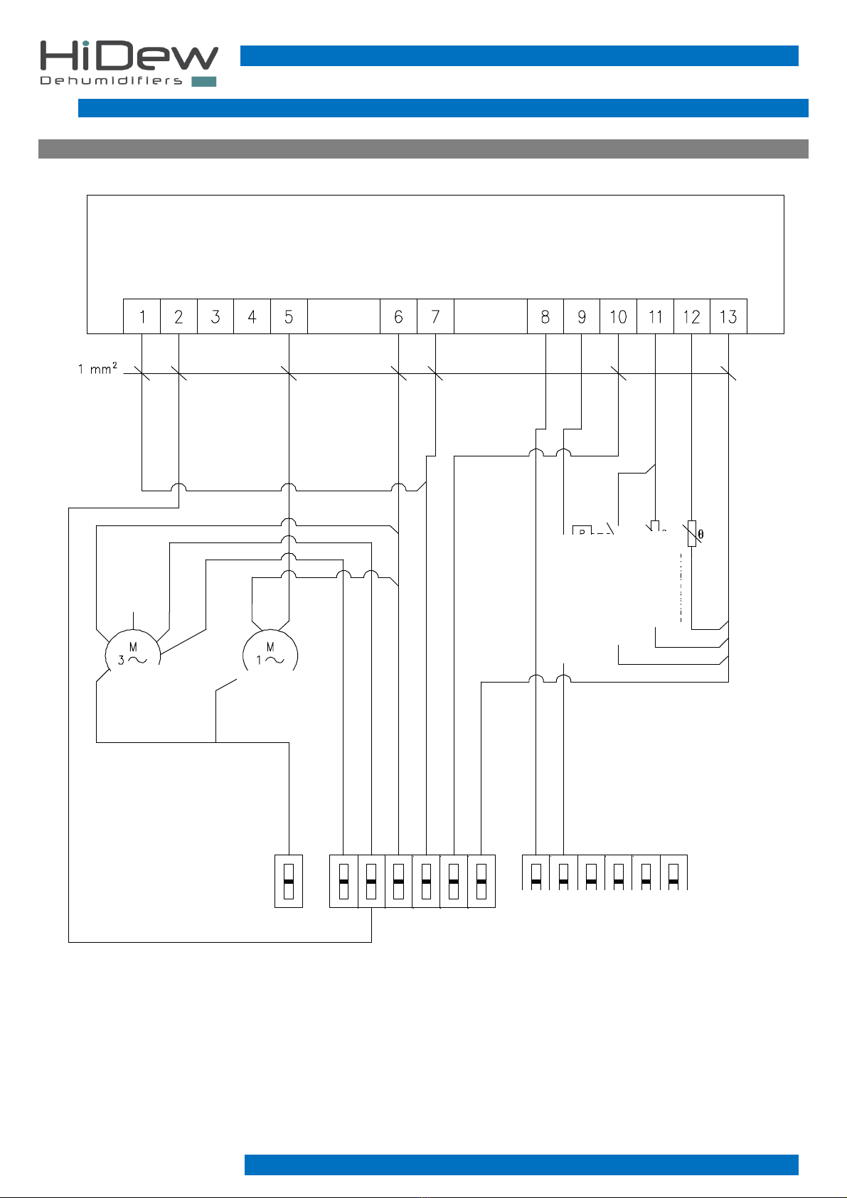
4.2 WIRING DIAGRAMS
WIRING DIAGRAM MODEL RS 020 A (isothe mal)
T1
SONDA TEMP
ACQUA INGRESSO
T2
SONDA TEMP
SBRINAMENTO
AP1
PRESSOSTATO DI ALTA
M2
COMPRESSORE
PE
7
6
N
F
5
4
PE 33
61
TERMINALE UTENTE
VENTILATORE
BIANCO
ROSSO
BLU
NERO
PE
2
1
61
N
F
F
1
2
5
4
MORSETTIERA OPZIONALE:
PRESENTE SOLO PER VERSIONE CON
COLLEGAMENTO SERIALE RS485
High pressure manostat
ater in temp probe
Defrost temp
probe
OPTIONAL CLAMPS BOARD: AVAILABLE ONLY
ITH RS 485 VERSION
USER TERMINAL
Compressor
Fan

USER
MANUAL
-
rev 08
RS
De
h
umidifi
ers for radiant systems
15 - 48
WIRING DIAGRAM MODEL RS 020 I (hyb id)
T1
SONDA TEMP
ACQUA INGRESSO
T2
SONDA TEMP
AMBIENTE
AP1
PRESSOSTATO DI ALTA
1 2 3 4 5 6 7 8 9 10 11 12 13
M2
COMPRESSORE
PE
7
6
N
F
5
4
PE 33
61
GAS
ELETTROVALVOLA
V1
32
TERMINALE UTENTE
VENTILATORE
BIANCO
ROSSO
BLU
NERO
PE
1
2
61
F
N
1
2
F
5
4
MORSETTIERA OPZIONALE:
PRESENTE SOLO PER VERSIONE CON
COLLEGAMENTO SERIALE RS485
USER TERMINAL
ater in temp probe
Defrost temp
probe
Compressor
Fan
OPTIONAL CLAMPS BOARD: AVAILABLE ONLY
ITH RS 485 VERSION
High pressure manostat
Gas electrovalve

rev 08
–
USER MANUAL
RS
De
h
umidifi
ers for radiant systems
16 - 48
WIRING DIAGRAM MODEL RSE 050 A (isothe mal)
1 2 3 4 5 6 7 8 9 10 11 12 13
COMPRESSORE
PE
N
F
5
4
PE
33
POTENZIOMETRO
31
21
22
23
F
N
F
VENTILATORE
PE - g/v
N - blu
L - marrone
10V - rosso
0-10V/PWM - giallo
GND - blu
Tacho - bianco
KM1 KM1
34
TERMINALE UTENTE
PA11
PRESSOSTATO
DI ALTA 1
ST11
SBRINAMENTO 1
SONDA TEMP
ST11
ACQUA INGRESSO
SONDA TEMP
2
1
1
2
5
4
FILI 1 E 2 OPZIONALI: PRESENTI SOLO
PER VERSIONE CON COLLEGAMENTO
SERIALE RS485.
High pressure manostat
ater in temp probe
Defrost temp
probe
Fan
Compressor
potentiometer
USER TERMINAL
IRES
1 AND 2: OPTIONAL, AVAILABLE ONLY
ITH OPTION RS 485

USER
MANUAL
-
rev 08
RS
De
h
umidifi
ers for radiant systems
17 - 48
WIRING DIAGRAM MODEL RSE 050 I (hyb id)
GAS
ELETTROVALVOLA
V1
1 2 3 4 5 6 7 8 9 10 11 12 13
COMPRESSORE
PE
N
F
5
4
PE
33
POTENZIOMETRO
31
21
22
23
F
N
F
VENTILATORE
PE - g/v
N - blu
L - marrone
10V - rosso
0-10V/PWM - giallo
GND - blu
Tacho - bianco
KM1 KM1
34
TERMINALE UTENTE
PA11
PRESSOSTATO
DI ALTA 1
ST11
SBRINAMENTO 1
SONDA TEMP
ST11
ACQUA INGRESSO
SONDA TEMP
32
2
1
1
2
5
4
FILI 1 E 2 OPZIONALI: PRESENTI SOLO
PER VERSIONE CON COLLEGAMENTO
SERIALE RS485.
USER TERMINAL
Gas electrovalve
potentiometer
Compressor
Fan
High pressure manostat
ater in temp probe
Defrost temp
probe
IRES 1 AND 2: OPTIONAL, AVAILABLE ONLY
ITH OPTION RS 485

rev 08
–
USER MANUAL
RS
De
h
umidifi
ers for radiant systems
18 - 48
5USER TERMINAL
The unit is delivered in “OFF” (to turn it on, keep pressed for more than 1 second the [STAND-BY] key, and it will turn to “ON”),
ready to function.
The control manages all the functions and the devices of the unit, by operating under the call from the external humidistat.
Remember that the compressor has a delay when starting and re-starting of 5 minutes, in order to avoid mechanical damages to the
internal components.
Every problem / error is displayed, according to the DIAGNOSTICS AND ALARMS table below.
By default, the ventilation is combined with the compressor starting.
Some of these regulations can be modify according to the PARAMETERS TABLE below.
5.1 DISPLAY AND KEYS

USER
MANUAL
-
rev 08
RS
De
h
umidifi
ers for radiant systems
19 - 48
1. UP Key (t)
Increases the values / Browses parameters.
Turns off the sound alarm, if present.
2. DO N Key (u)
Decreases the values / Browses parameters.
3. STAND-BY Key
Pushed for more than 1 second, it changes the OFF status to the ON one and vice-versa.
hen the status is changed, a sound signal is emitted.
In stand-by status, the plant stops and on the display you see the OFF writing.
4. SET Key
Allows to set the parameters.
Restores the sound alarm, if present.
Except from the programming, it has no functions.
5. TEMPERATURE / PARAMETERS Values
6. COLD CALLING Icon
Led OFF = Cold calling OFF
Led ON = Cold calling ON
Led flashing = Cold calling ON, but waiting for the re-starting time
7. HOT CALLING Icon (if active)
Led OFF = Hot calling OFF
Led ON = Hot calling ON
8. DEFROST CALLING Icon
Led OFF = Defrost calling OFF
Led ON = Defrost calling ON
9. FANS CALLING Icon
Led OFF = Fans calling OFF
Led ON = Fans calling ON
10. DIGITAL INPUT ACTIVATED BY HUMIDISTAT (if active)
Led On = Active digital input
Led flashing = Compressor off because of missed humidistat consent
11. ALARM Icon
Led OFF = No alarms present
Led flashing = Alarm present

rev 08
–
USER MANUAL
RS
De
h
umidifi
ers for radiant systems
20 - 48
5.2 USER PARAMETERS
To enter the user parameters setting menu, it is necessary to:
1. Keep pushed for 3 seconds the keys UP (t) and DO N (u) till you see on the display the first variable. hen entering the
menu, a sound signal will be emitted.
2. Select with the keys UP (t) or DO N (u) the variable you want to modify.
3. Now it is possible to change the value by keeping pushed the SET key and pushing the key UP (t) or DO N (u).
4. Once finished the setting, to exit the menu, keep pushed the keys UP (t) or DO N (u) (or wait 30 seconds without
pushing any keys) till the status of the unit (OFF or ON) appears on the display.
hen exiting from the menu, a sound signal will be emitted.
5. The memorizing of the modifications will be automatic after the exit from the configuration menu.
PARAM DESCRIPTION DEFAULT
SEc Setting temperature set-point (if active) 26,0
tAC
Display
temperatur
e
:
- water probe Reading
tEu
Display temperature
:
- coil probe - (version A isothermal)
- ambient probe - (versione I hybrid)
Reading
eL Software release Reading
For the dehumidifiers with cold integration, the defrost is cyclic, every 120 minutes.
This time is set by default.
5.3 OTHER FUNCTIONS
5.3.1 DEFROST MANUAL ACTIVATION
hen the activation conditions are satisfied (temperature read by the probe <5°C), it is possible to activate the defrost manually, by
pushing the (u) key for more than 3 seconds; a sound signal will be emitted as confirmation.
In this way, the defrost is activated by turning off the compressor and keeping on the fan.
5.3.2 END-DEFROST MANUAL FORCING
During the defrost, pushing the key (u) for 3 seconds, it is possible to force the end of the defrost; a sound signal will be emitted as
confirmation.
This function can not be activate from the programming menu.
Other manuals for RSO
1
This manual suits for next models
2
Table of contents
Other HiDew Dehumidifier manuals


