Hidro-Water XENA 10.1 Instruction Manual

2 3
MA-EN-OSMOSIS XENA10.1-RO-0220-22-FLC-21-V01.0 MA-EN-OSMOSIS XENA10.1-RO-0220-22-FLC-21-V01.0
1.- INTRODUCTION
This manual explains the installation and operation of equipment for water treatment by reverse
osmosis for household use. The equipment has been designed to be connected to the housing facility.
It is easy installation and operation as it has already been semi-assembled. It requires very little
assembly as it is only necessary to connect the hydraulics, electrics and install the faucet as indicated
in point 4 of this manual.
In the absence of installation and maintenance as described in this manual by technically
qualied personnel to ensure the quality of water produced and proper installation, the
warranty is void.
2.- PRECAUTIONS AND WARNINGS
Please read this manual carefully following the warnings listed below before going ahead
with the installation and use of the XENA 10.1 osmosis system. If you have any doubts, please
contact your distributer.
• For the correct operation of osmosis systems with a pump, the pressure should be between
1 and 3 bars, for this reason a pressure regulator has been supplied with the system to
be installed at the system inlet. In doing so, this will avoid damaging the pump and other
components of the system.
• The temperature of the water to be treated should not be below 5ºC nor above 35ºC to avoid
damaging the system.
• The osmosis system is designed to treat tap water with a maximum salinity of 1000 ppm. Do not use
in places where the water is not microbiologically safe or has an unknown quality. For water with a
greater salinity level, please contact your distributor.
• It is advisable that the water to be treated has been softened or with a maximum hardness of
15ºHF for optimum performance. Water with a hardness greater than 15ºHF will shorten the life
of the membrane.
• If the water has a high concentration of iron or magnesium, nitrate concentration greater than 100
ppm, sulphate concentrations greater than 250 ppm, more than 3 NTU turbidity and/or prolonged
use of high chlorine levels, please contact your distributor to suggest an appropriate pre-treatment
system to ensure the correct operation of the system.
• The osmosis system reduces the level of the following elements; aluminium, ar-senic, bromoform,
chlorine, chlorides, copper, conductivity, chrome, dibromo-chloromethane, uorides, nitrates,
oxidability, pH, selenium, sodium, sulphates, PAHs, trihalomethanes and other dissolved solids.
• If the osmosis system is not going to be used for a long period of time, close the water passage.
• Install the system on a at surface.
• Do not expose the system to direct sunlight or install it outdoors.
INDEX
1.- INTRODUCTION..........................................................................................................3
2.- PRECAUTIONS AND WARNINGS ............................................................................3
3.- CHECKING THE CONTENTS ....................................................................................4
4.- INSTALLATION...........................................................................................................6
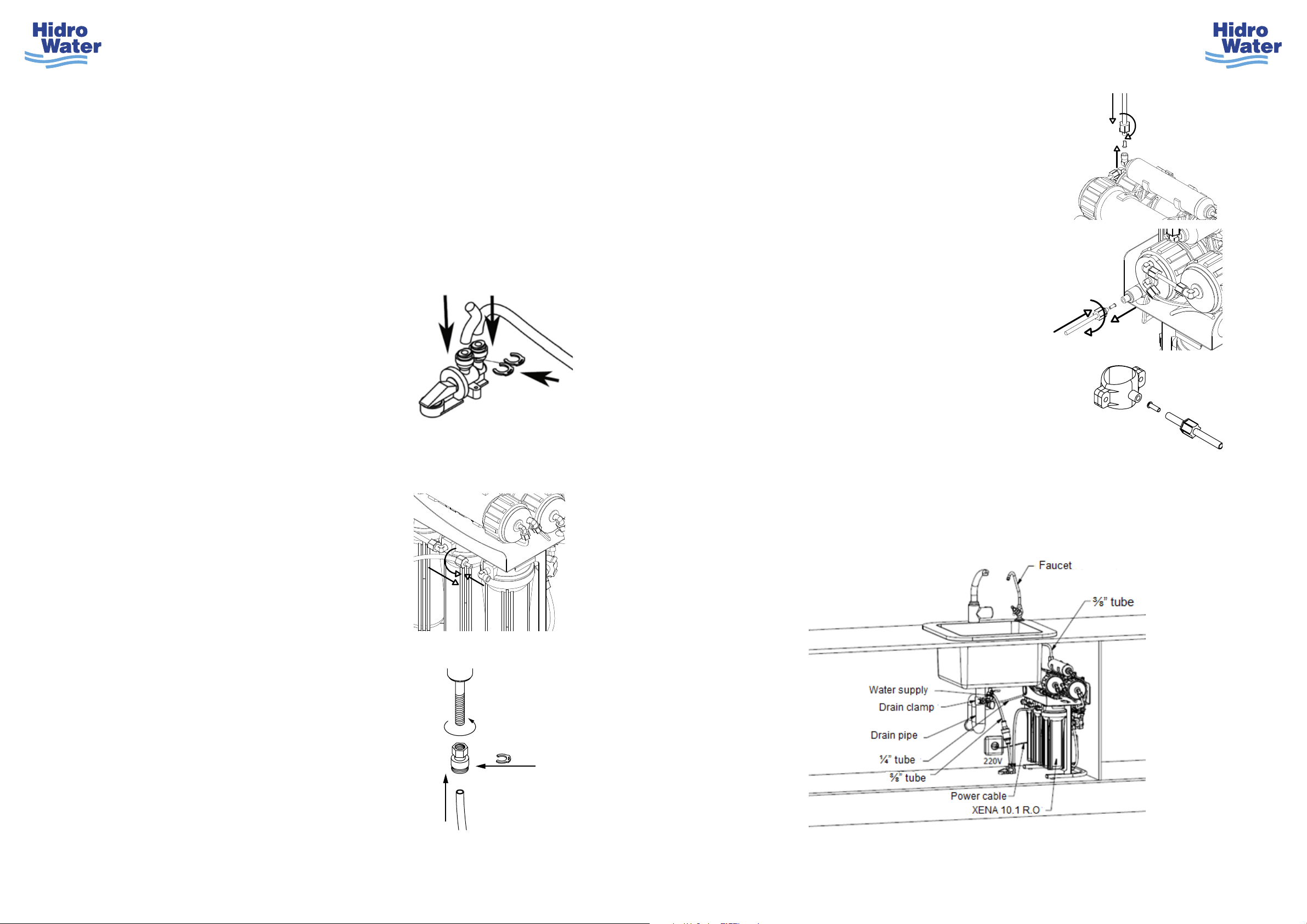
4.1.- Faucet installation (Figure-3)....................................................................................................... 6
4.2.- Water inlet installation (Figure-8 & Figure-9).............................................................................. 6
4.3.- Drain clamp installation (Figure-7) .............................................................................................. 7
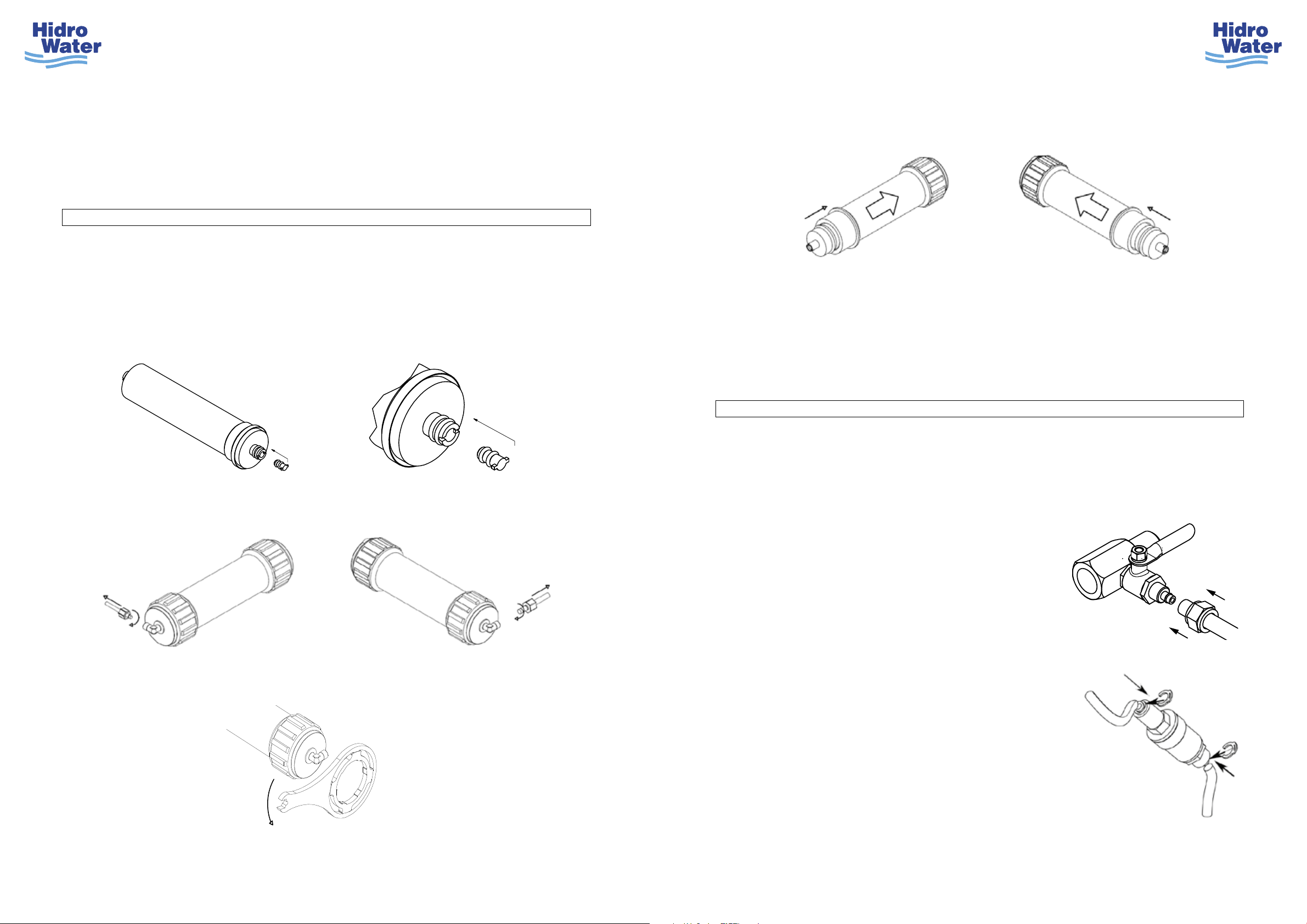
4.4.- Cartridge installation.................................................................................................................... 7
4.5.- Membrane installation.................................................................................................................. 8
4.6.- Osmosis system installation ....................................................................................................... 9
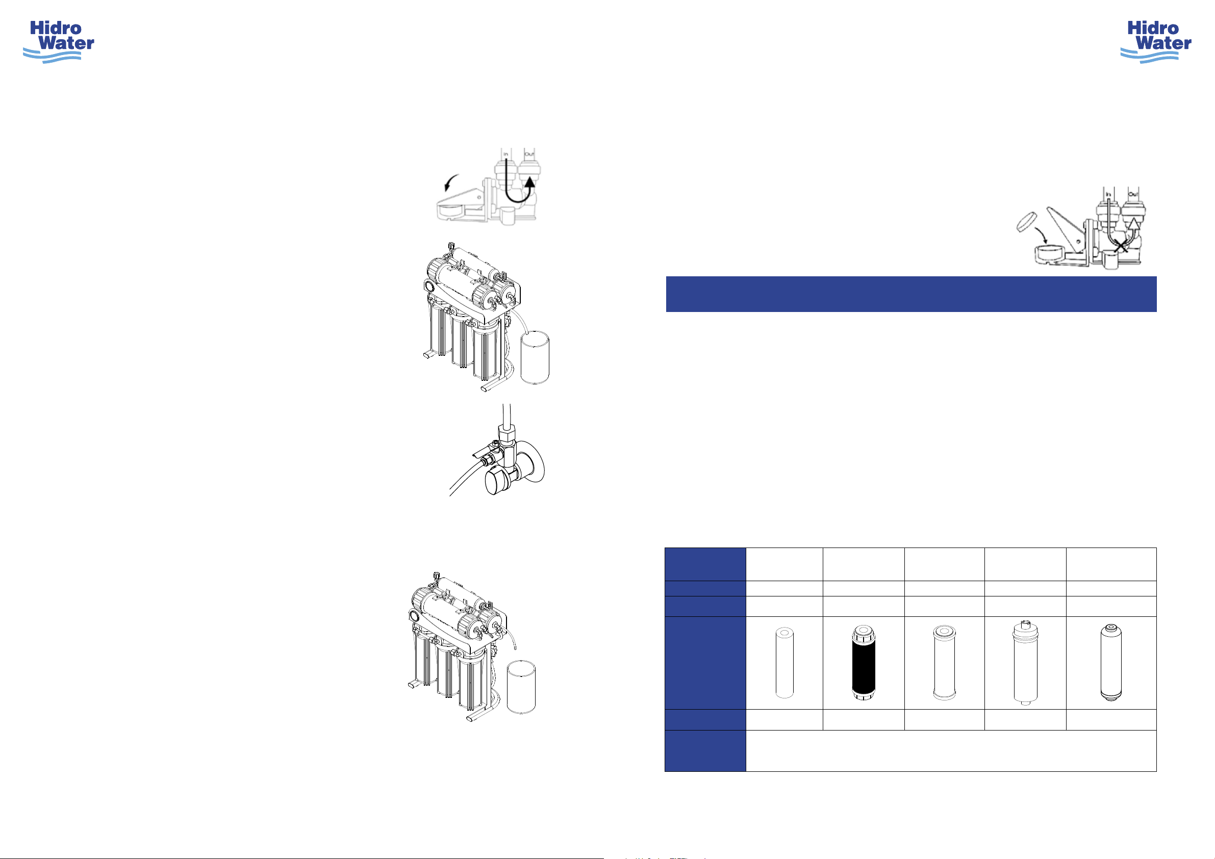
5.- OSMOSIS SYSTEM START-UP...............................................................................12
6.- INSTALLATION AND MAINTENANCE...................................................................13
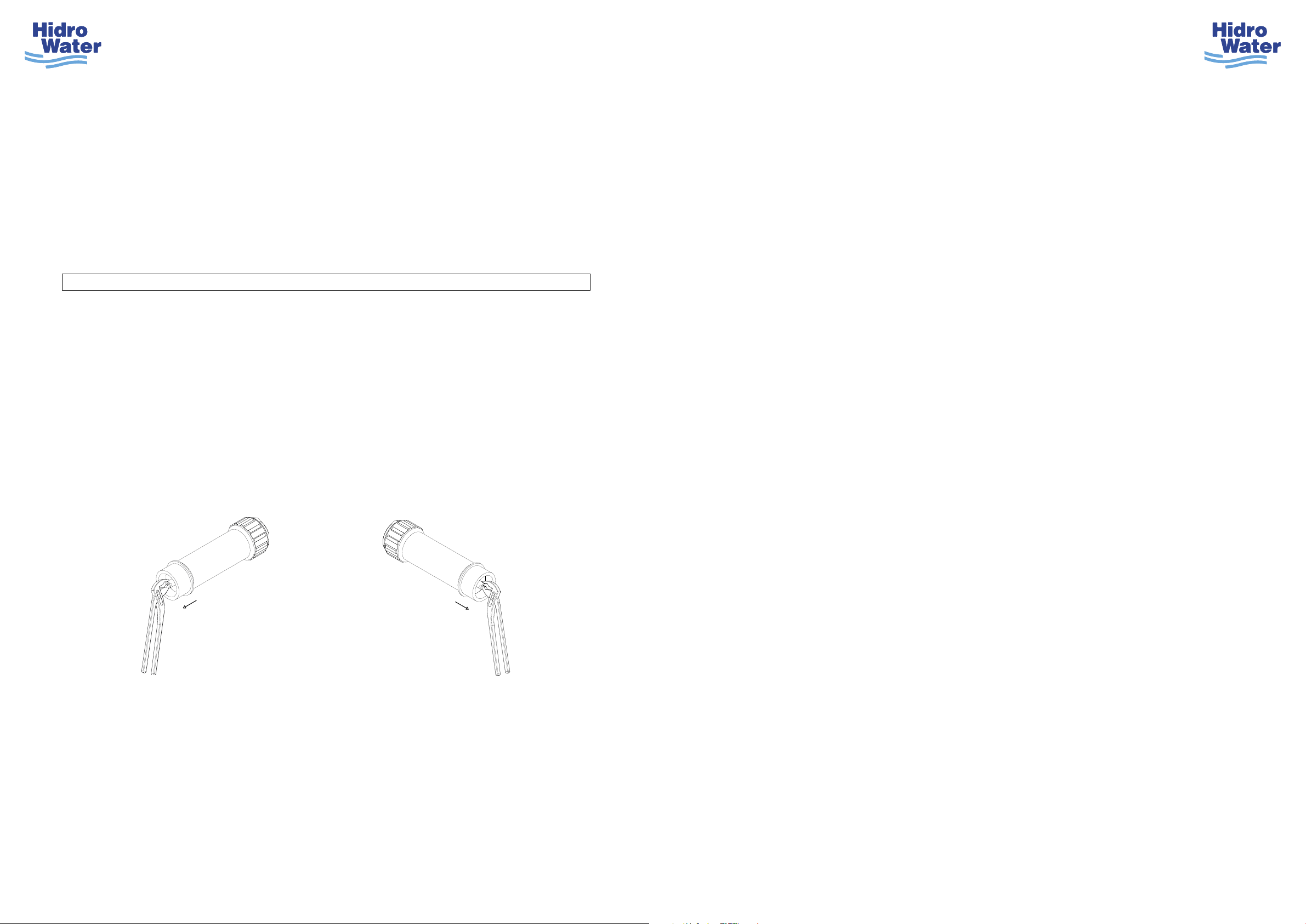
6.1.- Procedure for replacing cartridges and the membrane............................................................ 14
7.- FAULTS, PROBABLE CAUSES AND POSSIBLE SOLUTIONS...........................16
8.- MONITORING AND MAINTENANCE CONTROL ..................................................18
9.- SPARE PARTS ..........................................................................................................20

4 5
MA-EN-OSMOSIS XENA10.1-RO-0220-22-FLC-21-V01.0 MA-EN-OSMOSIS XENA10.1-RO-0220-22-FLC-21-V01.0
• The installation should be done by professionally qualied personnel and should not be installed
close to a heat source.
• The XENA 10.1 osmosis system needs a mains current of 220 – 240V less than 1 metre away.
• Do not repair or take the system apart on your own. If the system is not working correctly, contact
your distributor. Any tampering of the equipment by unauthorized personnel will result in the
warranty being void.
• Make sure the water passage is closed when a repair or maintenance is being carried out.
• During the rst installation or after changing the cartridges, black powder coming from the carbon
lter will enter the water. This is normal. Run the water until it’s clear.
• Do not bend the tubes to prevent ow and pressure blockages.
• Use original spare parts to assure the correct performance of the system.
• For installation, maintenance and cartridge change, please follow this manual; otherwise the
warranty will be void.
3.- CHECKING THE CONTENTS
Open the packaging and make sure that all of the components are inside, ready for the installation.
FIGURE DESCRIPTION
1XENA 10.1 Osmosis system main unit
223x12 200 GPD membrane
3Margarita faucet
4Filter/membrane housing wrench.
5¼” PE Tube
6⅜” PE Tube
7Waste clamp
8Feed adaptor
9¼” M x ¼” T Brass ball valve
10 ¼” Plastic insert
11 ⅜” Plastic insert
12 ⅜” Faucet tube adaptor
13 ⅜” WATER STOP Antileak system
14 ⅜” security clip
15 ⅜” pressure redactor
16 Instruction manual & warranty
X-1 X-2 X-1 X-1
FIGURE 1 FIGURE 2 FIGURE 3 FIGURE 4
X-1 X-1 X-1 X-1
FIGURE 5 FIGURE 6 FIGURE 7 FIGURE 8
X-1 X-2 X-3 X-1
FIGURE 9 FIGURE 10 FIGURE 11 FIGURE 12
X-1 X-1 X-1 X-1
FIGURE 13 FIGURE 14 FIGURE 15 FIGURE 16

ABC
ABC
6 7
MA-EN-OSMOSIS XENA10.1-RO-0220-22-FLC-21-V01.0 MA-EN-OSMOSIS XENA10.1-RO-0220-22-FLC-21-V01.0
a. Choose the location on the counter where you
want to install the faucet.
b. Use a drill with a 12mm bit to make a necessary
sized hole to put the faucet.
c. Fit the tap in the hole as indicated in the
image using a spanner (our reference: OI-
0207-128 not supplied with system) to adjust
it tightening the nut.
a. The water supply input consists of two parts; a brass ball valve (Figure-9) and an adaptor
(Figure-8). The brass ball valve must be screwed to the adaptor using enough Teon on its
thread, as shown in the image below.
b. Turn o the water supply at the point where you are installing the osmosis system.
c. The water supply input is designed to be used with hoses with a ⅜” connection. Insert the
water feed adapter with the brass ball valve between the cold water supply and the hose.
(Never install a hot water connection as the osmosis system will be damaged). Make sure that
the brass ball valve is closed.
4.1.- Faucet installation (Figure-3)
4.2.- Feed Adapter installation (Figure-8 & Figure-9)
4.- INSTALLATION
The system can be installed anywhere in the residence where there is a water input, a drain
for water waste, a 220 – 240 V socket within a metre and sucient space to be located. The most
common place is under the kitchen sink. The installation should be carried out by qualied personnel.
a. The cartridges come pre-installed in the system’s lters,
but you must remove the plastic packaging they’re in
before using the system. To do so, you must remove the
lter housing at the bottom of the system using the wrench
supplied with the system (Figure 4) as shown in the gure;
remove the cartridges and remove the packaging.
a. The drain clamp is designed to adjust the drainpipe
sealing to 1 ½”.
b. The drain clamp should always be installed above the
U-bend (before it) and in the case of a horizontal drainpipe,
install it above (at the top). Do not install it near to the waste
outlet as it could clog the drainpipe.
c. Drill a 6mm hole in the drainpipe.
d. Align the clamp hole with the hole in the drainpipe and
carefully tighten the screws on the clamp until it is xed into
place. Do not over tighten.
4.3.- Drain clamp installation (Figure-7)
4.4.- Cartridge installation
b. Place the new cartridges making sure they are tted in the correct order as shown in the gure
below to assure a good operation of the osmosis system.
A
2 3 4 5 6 7 8
1 2 3 4 5 6 7 8
B
C
D
E
F
A
B
C
D
E
F
Cover plate
Upper O-ring
Lower O-ring
Plastic Fixing
Nut
3/8” Faucet Adapter
Washer
Margarita Faucet
3/8” Security clip
Brass ball valve
Connect 3/8” hose
Adapter
Connect to water
supply
Connecto to the osmosis
system with 3/8” tube
Place teflon

8 9
MA-EN-OSMOSIS XENA10.1-RO-0220-22-FLC-21-V01.0 MA-EN-OSMOSIS XENA10.1-RO-0220-22-FLC-21-V01.0
To t the membrane (Figure-2) in the membrane housing correctly, the membrane must be
taken out of its packaging and proceed as follows:
a. Place the plug that comes with each of the membranes in the end of the permeate port of the
membrane which has two slits as shown in the following diagram.
4.5.- Membrane installation
b. Unscrew the inlet elbow nut on each of the membrane housing to be able to open the lid.
c. Open the membrane housing turning it anti-clockwise with the help of the wrench supplied
with the system (gure 4).
d. Insert the membranes in the correct direction as shown in the following gure. They must
be tted following the arrows on the respective membrane housing, introducing the end that
doesn’t have the big exterior seal rst.
c. Unscrew the filter housing checking that the cartridges are centered, so they ad-just
properly with the filter adapter and cup.
d. Tighten the lter housing with using the wrench supplied with the system (gure 4).
e. Once the membranes have been tted, close the membrane housing lid clock-wise with the
help of the wrench supplied with the system (gure 4). Then screw the inlet elbow nuts back
on the membrane housing
a. Place the osmosis system in the chosen location.
b. Connect ⅜” tube (gure 6) to the brass ball valve
connected water supply inlet (gure 9).
c. The other end of the ⅜” tube must be connected to
the inlet of the pressure reducer (gure 15); to do
so, you must remove the blue safety clip on the inlet
and insert the tube fully. Once you have inserted the
tube, put the ⅜” safety clip back on (the pressure
reducer has a label with an arrow which indicates
the water ow.
The hydraulic connections should follow the contour of the surface chosen for installation so
that the tubes do not get mixed up or tangled. Leave a sucient length of tube to ease moving the
system during future maintenance. Here are the steps to follow to make the hydraulic connection:
4.6.- Osmosis system installation

10 11
MA-EN-OSMOSIS XENA10.1-RO-0220-22-FLC-21-V01.0 MA-EN-OSMOSIS XENA10.1-RO-0220-22-FLC-21-V01.0
f. The WATER STOP Antileak system (Figure 13)
must be xed to the base of the unit where you’re
installing the osmosis system, xing it with the
adhesives supplied.
g. Once you have xed the WATER STOP Antileak
system in the chosen place, you must connect the ⅜”
tube to the outlet of the Antileak system (gure 13),
marked “OUT”, inserting it fully. Once it is inserted,
replace the ⅜” security clip (gure 14).
h. The other end of the ⅜” tube must be connected to
the inlet of the XENA 10.1 osmosis system (gure 1),
where it is marked “ENTRADA”. To do so, you must
unscrew the inlet elbow nut on the osmosis system
and insert the ⅜” tube through the nut and into the
system, having previously inserted a ⅜” plastic insert
(gure 11). Screw the nut back on the system.
i. Screw the faucet adapter (Figure-12) to the faucet.
Then connect ⅜” tube (Figure-6) to the faucet adapter.
Insert it fully. Once inserted put on the ⅜” security clip.
j. The other end of the ⅜” tube must be inserted
through the nut on the outlet of the post lter marked
“GRIFO”. Screw the nut back on having previously
insert-ed a ⅜” plastic insert (gure 11).
k. Unscrew the nut on the relief valve which is marked
“DESAGÜE”. Insert the ¼” tube (gure 5) through
the nut and place a ¼” plastic insert (gure 10) on
the end. Screw the nut back on.
l. The other end of the ¼” tube must be inserted through
the nut on the drain clamp (gure 7). After inserting
the corresponding ¼” plastic insert, screw the nut
back on the drain clamp.
m. Connect the XENA 10.1 osmosis system’s plug into
the electricity supply of 220-240V.
Here is a diagram of how the system should be installed.
d. Connect the ⅜” tube (figure 6) to the outlet of the pressure reducer (figure 15); to do so,
you must remove the blue safety clip on the outlet and insert the tube fully. Once you
have inserted the tube, put the ⅜” safety clip back on (the pressure reducer has a label
with an arrow which indicates the water flow).
e. The other end of the ⅜” should be connected to the inlet of the WATER STOP Antileak
system (figure 13) where it is marked “IN”, inserting it fully. Once it is inserted, replace
the ⅜” security clip (figure 14).

12 13
MA-EN-OSMOSIS XENA10.1-RO-0220-22-FLC-21-V01.0 MA-EN-OSMOSIS XENA10.1-RO-0220-22-FLC-21-V01.0
f. Close the brass ball valve at the water inlet (gure 9) and reconnect the tube to the rst
membrane housing by screwing on the corresponding nut.
g. Release the ¼” tube that is connected to the osmosis
system’s elbow nut on the post lter by unscrewing the nut
and facing it towards a bucket or container.
h. Once again open the water supply and then the ball
valve (gure 9). Let the water run between 6 – 10
minutes to remove a chemical product that has come
from the membrane which is used to protect them
from microbiological contamination. This product isn’t
dangerous but could aect the taste.
b. Make sure that the arm on the WATER STOP Antileak
system is down as shown in the figure so that the water
can enter the system.
c. Release the ⅜” tube that is connected to the osmosis
system’s first membrane housing by unscrewing the
nut and facing it towards a bucket or container.
d. Open the water supply and then the ball valve (gure 9) as
shown. Make sure there is no water leak. If there is, close
the valve and x it.
e. Let the water run until it’s clear. This way we can make
sure that there isn’t any residue trapped in the membrane
that the granular carbon lter could have let o.
5.- OSMOSIS SYSTEM START-UP
a. Make sure that all the connections are connected properly and tightened and the XENA
10.1 system is connected to the 220 – 240V power supply.
i. Close the brass ball valve at the water inlet (gure 9) and reconnect the tube to the post lter
by screwing on the corresponding nut.
Open position
CONGRATULATIONS! YOUR SYSTEM IS ALREADY FULLY INSTALLED AND RUNNING
j. Open the brass ball valve again (gure 9) and turn the faucet (gure 3) on. In doing so, the
system will start to produce water. If the water has a black colour don’t worry, this is normal.
It’s caused by the residue the carbon activated granular cartridge lets o.
k. Raise the arm of the WATER STOP Antileak system and place a piece of absorbent material
as indicated in the picture. Put away the other piece to use as a spare. Lower the arm so that
water can enter the osmosis system and continue to produce water.
l. Once it runs clear, turn the faucet off.
m. The system is now ready for use.
Cartridge type Sediments
cartridge
Carbon GAC
cartridge
Carbon CTO
cartridge Membrane Postlter
Stage 1st 2nd 3rd 4th & 5th 6th
Reference CA-1203-02 CA-0604-08 CA-0608-03 ME-2312-02 OI-0205-18
Appearance
Replace* 6 - 9 months 6 - 9 months 6 - 9 months 2 – 3 years** 12 months
Sanitation
Every time you change a cartridge, the membrane or a component in contact with water or
if you haven’t consumed water in over a month, you must sanitise the system using
the Sanitising kit (OI-0207-131). Not supplied with the system.
6.- INSTALLATION & MAINTENANCE
The installer should inform the family members of the following points of the Reverse
Osmosis System:
a. Location of the water inlet, storage tank valve, faucet, drain clamp and the plug that
connects the osmosis system to the mains supply.
b. Uses for purified water (cooking, to make coffees & teas, drinking, ice cubes, ironing,
fish tanks…)
c. Maintaining the osmosis system. The recommended maintenance of the osmosis
system is in the table below. By not following the maintenance as described in this
manual, using original cartridges and by authorized personnel that guarantees the
quality of the water produced and the correct operation of the osmosis system,
the warranty will be void.

14 15
MA-EN-OSMOSIS XENA10.1-RO-0220-22-FLC-21-V01.0 MA-EN-OSMOSIS XENA10.1-RO-0220-22-FLC-21-V01.0
*The life of the lters and membranes will vary depending on the quality of the water supply,
the usage and the amount of impurities it has.
**The duration of the membrane will be approximately 2 – 3 years given that mains water’s
conductivity is equal to or inferior to 1000ppm and the hardness is between 0 – 15ºF. If the water
supply’s characteristics, if applicable, are dierent, then the conditions regarding the replacement of
the membranes will change.
Replace the cartridges in the given period to ensure the life of the membrane and the quality
of the water obtained.
6.1.- Procedure for replacing cartridges and the membrane
a. Close the water supply brass ball valve (gure 9) and disconnect the system from the
power supply.
b. Open the faucet (gure 3) to relieve the pressure from inside the osmosis system.
c. To change the sediments (1st stage), carbon GAC (2nd stage) and carbon CTO (3rd stage)
cartridges; unscrew the 3 housing lters with the help of the wrench supplied with the system
(gure 4) and remove the used cartridges. Once removed, follow the process as described in
point 4.4 of this manual.
d. To change the membranes (4th & 5th stage) follow the process as described in point 4.5 of this
manual having previously removed the used membrane with the help of an adjustable wrench.
e. To change the inline post lter (6th stage), unscrew the nuts on the two elbow pieces it has,
take o the nuts and elbow piece on the post lter. Remove the used post lter from the
clamps that hold it in place.
f. Remove the post lter from its original packaging, remove the protective plugs on each end
and place the new post lter on its corresponding plugs, paying at-tention to the arrows on the
post lter which indicate the water ow. Make sure the post lter is tted the right way because
otherwise the water won’t ow correctly.
g. Apply sucient Teon to the threads of the elbow piece that we took o the post lter and
screw them back on the new lter. The elbow piece for the ⅜” tube should be screwed
on the output of the post lter and the elbow piece for the ¼” tube to the input. Insert the
corresponding tubes and screw on the corresponding nuts..
h. Once you have changed one of the cartridges, turn o the faucet (gure 3), open the water
supply brass valve (gure 9), connect the system to the power supply and check that there
are no water leaks. If there is close the valves and x it.
Precaution 1: If there is any leak on the connection part of the tube, take it o and cut o 0.5
cm. Then reconnect it. If there is a leak coming from a thread, unscrew the piece, apply more Teon
and screw it back on again.
Precaution 2: When you change the sediment, carbon GAC and carbon CTO cartridges
from the 1st, 2nd and 3rd stage, you must follow steps c, d, e and f in point 5 of this manual,
previously closing and then posteriorly opening the water supply brass ball valve as well as previously
disconnecting and posteriorly reconnecting the system to the power supply.
Precaution 3: When you change the membrane (4th & 5th stage), you must follow steps g, h,
i and j in point 5 of this manual.
Precaution 4: When you change the inline post lter (6th stage), if the water runs with a
blackish colour, do not worry, this is normal. It is caused by the residue that the granulated active
carbon lets o. Let the water run until it’s clear. Throw away the black-coloured water.

16 17
MA-EN-OSMOSIS XENA10.1-RO-0220-22-FLC-21-V01.0 MA-EN-OSMOSIS XENA10.1-RO-0220-22-FLC-21-V01.0
ID SYMPTOM PROBABLE CAUSE SOLUTION
1Zero/low
production
No water supply. Wait until the water supply has
been restored.
Brass ball valve at entrance
fully/partially closed. Open the entrance valve fully.
Insucient supply pressure.
Check mains pressure. If it is lower than
2.5 bars, then you must install a pump
and its respective switches.
Flow restrictor obstructed. Replace ow restrictor.
Drain obstructed. Check if the drain line is blocked. If so,
unblock it.
Excessive waste. Check the ow in the ow restrictor,
if excessive, replace it.
Cartridges obstructed. Replace cartridges.
Membrane saturated. Replace membrane.
No power supply.
Check the property’s power supply or socket.
Check voltage at transformers output.
If there isn’t any, replace it.
Pump in poor condition. Check that the pump increase pressure at the
membrane housing inlet. If it doesn’t, change it.
Antileak system activated
Check if the antileak system has activated
itself. If so, detect the leak, x it, replace
the absorbent material and lower the arm.
2
Excessive
production
and/or
elevated TDS
The membrane hasn’t been tted. Fit membrane.
Damaged membrane O-rings. Replace the O-rings on the membrane.
Damaged membrane housing. Replace the membrane housing.
Membrane damaged. Replace the membrane.
Badly connected tubes. Wire the connection between the wastage
and the permeate properly.
Damaged shut o valve. Replace shut o valve.
3Bitter or
acidic taste Water with very low salinity level. Fit a mineralizing postlter.
7.- FAULTS, PROBABLE CAUSES AND POSSIBLE SOLUTIONS ID SYMPTOM PROBABLE CAUSE SOLUTION
4Plastic or
synthetic taste Worn postlter. Replace postlter.
5Unpleasant
taste and smell Contamination. Change the lters, membrane, postlter
and sanitise.
6White particles
in the water
Air in the system. Wait for the air to pass as there’s no urgent
problem.
Excessive inlet
pressure.
Check the mains water pressure, if it is greater
than 4 bars it will be necessary to t a pressure
regulator at the inlet to the osmosis system.
7
The osmosis
system doesn’t
stop throwing
water away
Shut o valve
deteriorated. Replace shut o valve.
Non-return
valve deteriorated. Replace non-return valve.
Excessive inlet
pressure.
Check the mains water pressure, if it is greater
than 4 bars it will be necessary to t a pressure
regulator at the inlet to the osmosis system.
8
The osmosis
system starts up
sporadically
without water
consumption
Non-return
valve deteriorated. Replace the non-return valve.
Excessive
inlet pressure.
Check the mains water pressure, if it is greater
than 4 bars it will be necessary to t a pressure
regulator at the inlet to the osmosis system.
Leak in some point
of the system
and/or faucet.
Repair the leak and/or replace faucet.
9
The osmosis
system stops and
starts.
Very little inlet pressure,
less than 1 bar.
Bypass the minimum pressure switch (Danger
that the pump could work without water and break.
Minimum pressure
switch in bad condition. Replace the minimum pressure switch.
Deteriorated non-return
valve. Replace the non-return valve.

18 19
MA-EN-OSMOSIS XENA10.1-RO-0220-22-FLC-21-V01.0 MA-EN-OSMOSIS XENA10.1-RO-0220-22-FLC-21-V01.0
DATE: / /
SERVICE MADE NEXT SERVICE OBSERVATIONS
Sediments, GAC y CTO antibacterial cart.
change
/ /
Membrane change
/ /
Postlter change
/ /
Sanitization
/ /
Reparation
/ /
Name and signature of the authorised technician or distributor:
DATE: / /
SERVICE MADE NEXT SERVICE OBSERVATIONS
Sediments, GAC y CTO antibacterial cart.
change
/ /
Membrane change
/ /
Postlter change
/ /
Sanitization
/ /
Reparation
/ /
Name and signature of the authorised technician or distributor:
DATE: / /
SERVICE MADE NEXT SERVICE OBSERVATIONS
Sediments, GAC y CTO antibacterial cart.
change
/ /
Membrane change
/ /
Postlter change
/ /
Sanitization
/ /
Reparation
/ /
Name and signature of the authorised technician or distributor:
DATE: / /
SERVICE MADE NEXT SERVICE OBSERVATIONS
Sediments, GAC y CTO antibacterial cart.
change
/ /
Membrane change
/ /
Postlter change
/ /
Sanitization
/ /
Reparation
/ /
Name and signature of the authorised technician or distributor:
DATE: / /
SERVICE MADE NEXT SERVICE OBSERVATIONS
Sediments, GAC y CTO antibacterial cart.
change
/ /
Membrane change
/ /
Postlter change
/ /
Sanitization
/ /
Reparation
/ /
Name and signature of the authorised technician or distributor:
DATE: / /
SERVICE MADE NEXT SERVICE OBSERVATIONS
Sediments, GAC y CTO antibacterial cart.
change
/ /
Membrane change
/ /
Postlter change
/ /
Sanitization
/ /
Reparation
/ /
Name and signature of the authorised technician or distributor:
DATE: / /
SERVICE MADE NEXT SERVICE OBSERVATIONS
Sediments, GAC y CTO antibacterial cart.
change
/ /
Membrane change
/ /
Postlter change
/ /
Sanitization
/ /
Reparation
/ /
Name and signature of the authorised technician or distributor:
DATE: / /
SERVICE MADE NEXT SERVICE OBSERVATIONS
Sediments, GAC y CTO antibacterial cart.
change
/ /
Membrane change
/ /
Postlter change
/ /
Sanitization
/ /
Reparation
/ /
Name and signature of the authorised technician or distributor:
8.- MONITORING AND MAINTENANCE CONTROL

20 21
MA-EN-OSMOSIS XENA10.1-RO-0220-22-FLC-21-V01.0 MA-EN-OSMOSIS XENA10.1-RO-0220-22-FLC-21-V01.0
9.- SPARE PARTS ID CODE DESCRIPTION QNT
1OI-0207-139 WATER STOP Antileak system 1
2OI-0207-133 Absorbent material for Antileak system 2
3OI-0207-141 ⅜” T 40 psi Pressure regulator 1
4OI-0234-02 10” White housing lter 3
5OI-0230-09 Feed adapter 3/8”M x ¼” H x 3/8” F 1
6OI-0207-20 Drain Clamp 1
7OI-0210-03 ¼” M x ⅜” T Brass valve 1
8OI-0234-10 5 in 1 Wrench 1
9TU-0604-01 ¼” PP tube 1
10 TU-0602-01 ⅜” PP tube 1
11 OI-0236-20 Power supply 220 V- 24 V 5A 1
12 OI-0208-23 Mixed TEE 1/4”M x 3/8”T x 3/8”T 1
13 OI-0236-14 HF-45LN Pump 1
14 CA-1203-02 9 7/8” Sediments cartridge 5 microns 1
15 CA-0604-08 10” carbon GAC cartridge 1
16 CA-0608-03 9 7/8” carbon Block Cartridge 1
17 OI-0210-12 Elbow ¼” M x ⅜” T 5
18 OI-0230-26 1200 cc Flow restrictor 1
19 OI-0208-32 Male connection Non-return ¼” T x ¼” T quick tting 2
20 OI-0205-18 2 x 10” Antibacterial Nanosilver in-line post lter 1
21 ME-2312-02 23x12 200GPD Membrane 2
22 OI-0236-60 ¼” F 10A Maximum pressure switch 1
23 OI-0236-90 Mixed TEE ⅜” T x ¼” T x ⅜” M T 1
24 TG-A6UC4 Male connection ⅜” T x ¼” T 2
25 OI-0234-46 Shut o valve ⅜” 1
26 OI-0206-15 Tee ¼” T x ¼” T x ¼” T 1
27 TG-A6ME6 Elbow ¼” M x ¼” T 5
28 PO-0203-07 Membrane housing 27x12 2
29 OI-0234-72 ¼” F 15A Minimum pressure switch 1
30 OI-0207-16 2” x 2 1/2” Double clamp 2
31 OI-0207-42 2 1/2” x 2 1/2” Double clamp 2
32 OI-0234-100 2 1/2” Simple clamp 2
33 OI-0230-24 Margarita faucet 1
34 OI-0207-117 XENA 10.1 metal bracket 1
35 OI-0234-54 XENA 10.1 Pressure gauge 1
36 OI-0208-24 ⅜” Faucet tube adapter – quick connection 1
37 OI-0208-13 ⅜” M x ⅜” T Elbow piece 2
*OI-0207-01 Feed adapter kit (OI-0210-02 + OI-0230-09) 1
*CA-7003-02 Cartridge kit (3) 1
*CA-7003-03 Cartridge kit (4) 1
*CA-7006-06 Mineralisation and antibacterial postlter replacement kit 1

22 23
MA-EN-OSMOSIS XENA10.1-RO-0220-22-FLC-21-V01.0 MA-EN-OSMOSIS XENA10.1-RO-0220-22-FLC-21-V01.0
NOTES
NOTES

Hidro Water, S.L.U.
Ctra. Aldaya-Chirivella, 48
46960 Aldaya · Valencia, Spain
Tel: (+34) 961 98 62 30
hidrowater@hidro-water.com
www.hidro-water.com
MA-EN-OSMOSIS XENA10.1-RO-0220-22-FLC-21-V01.0
Hidro Water, S.L.U.
Carretera Chirivella-Aldaya, 48
46960 Aldaya · Valencia, Spain
Tel: (+34) 961 98 62 30
hidrowater@hidro-water.com
www.hidro-water.com
DISTRIBUTOR INSTALLER
Sale date Instalation date
Stamp: Stamp:
Table of contents
Other Hidro-Water Water Filtration System manuals
Popular Water Filtration System manuals by other brands

UV Dynamics
UV Dynamics UVD1000 Installation and maintenance manual

HoMedics
HoMedics AP-T10FL Replacement

KENT
KENT Grand 11007 Instruction handbook

Midea
Midea JL1645T-Z instruction manual

wavin
wavin minipek Installation, use and maintenance instructions

Sea Recovery
Sea Recovery Aqua Mini 170 owner's manual