Blake Water Solutions Specialist Series Guide
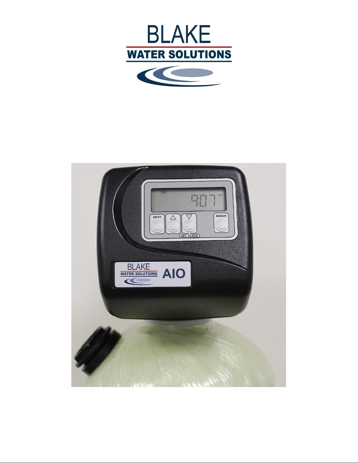
XOWSEEAIO REV 06/2018
OPERATION AND INSTRUCTION MANUAL
SPECIALIST SERIES AERATION FILTER SYSTEM
For Residential Filter Systems with Clack WS1EE (4 Button) AIO Control Valve

www.blakeequip.com
Peak Performance Solutions
Integrity Excellence Teamwork Innovation
Index
Introduction / Installation Requirements
Page 1
Installation & Commissioning
Page 2
Filtration Media Loading
Page 3
Backwash / Regeneration Cycles
Page 4
Bypass Valve
Page 5
Controller
Page 6
Programming: Setting Time of Day / Installer Settings
Page 8
Programming: System Setup
Page 9
Replacement Parts
Page 10
Filtration Media Overview
Page 11
1 of 11
Integrity Excellence Teamwork Innovation
Introduction
Blake Water Solutions’ Specialist Series™ point-of-entry (POE) Aerating Iron Oxidizer (AIO) filter systems function as a
regenerable water treatment unit utilizing oxygen instead of potentially harmful chemicals to rejuvenate and enhance the
performance of the selective filtration media. The filtration media provided is specific to the water contaminant or contaminants
that your water treatment specialist has identified.
The AIO system utilizes the Clack WS1EE control valve equipped with air injection capability to remove ferrous (or clear water)
iron, manganese, and sulfur from the water by both oxidation and filtration. During the regeneration cycle, an air bubble is
established in the head space of the filter tank above the media. Then, during service, as untreated water enters the tank, it mixes
with the air. Oxygen present in the air oxidizes some of the iron and managese that are present in the water, causing them to
precipitate into particles which become trapped in the filter media. The remaining dissolved iron and manganese precipitate out in
the filter bed as they are oxidized by the catalytic reactions occurring on the media surface.
Unlike other iron filter alternatives, the Clack WS1EE AIO technology is designed for use in a single tank / valve system
configuration, reducing both installation and maintenance costs, yet delivering years of trouble-free service. No chemical additives
or air compressors are required for operation or regeneration with the Clack WS1EE AIO’s unique and advanced design.
Do not install this system if methane is present in the water - DANGEROUS DEADLY GAS CAN ACCUMULATE
This system is not intended to be used for treating water that is microbiologically
unsafe or of unknown quality without adequate disinfection before or after the system.
Installation Requirements
WATER PRESSURE: A least 30 psi of water pressure (2.7bar) is required for the injector to draw air and operate effectively.
CAUTION: Water pressure must not exceed 80psi (5.5 bars), water temperature is not to exceed 110°F (43°C), and the unit cannot
be subjected to freezing conditions.
NOTE: Due to the air pocket, exceeding 80PSI will adversely impact performance.
ELECTRICAL FACILITIES: An uninterrupted 120 VAC supply is required. The valve is supplied with a 12 VAC transformer.
Please make sure your voltage supply is compatible with your unit before installation.
EXISTING PLUMBING: Condition of existing plumbing should be free from scale and iron buildup. Piping that is built up heavily
with scale and/or iron should be replaced.
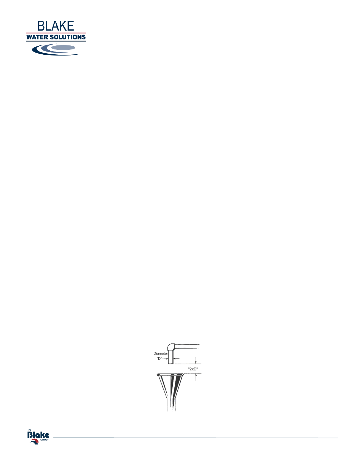
LOCATION OF FILTER AND DRAIN: The filter should be located close to a drain to prevent air breaks and back flow.
DRAIN AIR GAP: Always provide the proper air gap distance of two drain pipe diameters.
2 of 11
Integrity Excellence Teamwork Innovation
Installation & Commissioning
1. Note this system is supplied without media installed for ease of transportation and simplifying site location. Refer to the
section of this manual for Media Filtration Installation Guide/Commissioning.
2. Place the tank where you want to install the unit making sure the unit is level and on a firm base.
3. During cold weather, the installer should warm the valve to room temperature before operating.
4. All plumbing must be done in accordance with local plumbing codes. The pipe size for residential drain line should be a
minimum of 1/2” (13 mm). Backwash flow rates in excess of 7 gpm or length in excess of 20’ require 3/4” drain line.
Commercial drain lines should be the same size as the drain line flow control. Due to the release of the air during
regeneration, the drain line must be secured at the end, and anchored throughout the run.
5. Ensure that the check valve supplied with the AIO control valve is securely installed inside the control valve inlet. This is
required to prevent the pressurized air bubble inside the oxidizer tank from venting backwards up the feed water plumbing.
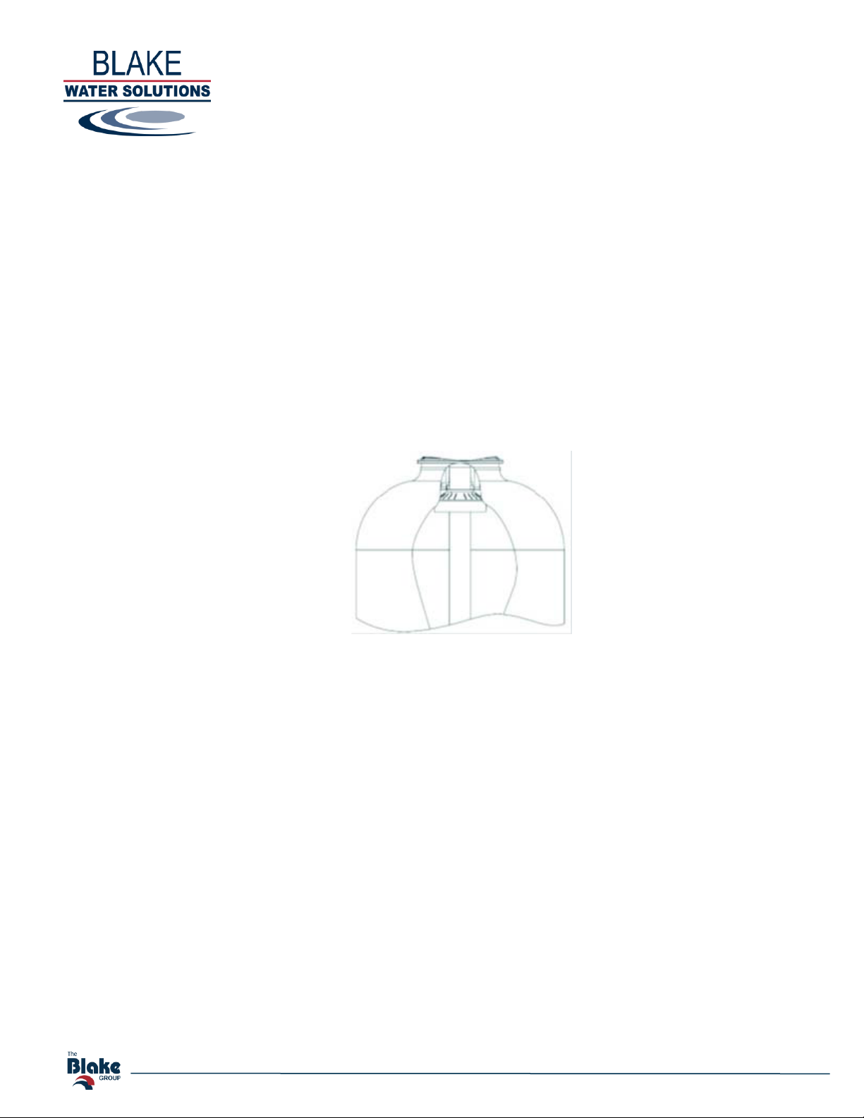
6. If not factory installed assemble the deflector to the distributor tube:
Put a thin layer of silicone lube around inside diameter of the deflector. Slowly slide the deflector over the distributor tube
down about 1”. When threading the AIO valve to the tank, the bottom of the threads will slide the deflector down. As
shown below.
7. Lubricate the distributor O-ring and tank O-ring. Place the main control valve on tank. Note: Only use silicone lubricant.
8. Solder joints near the inlet / outlet / drain must be done prior to making thoses connections. Leave at least 6” (15 cm)
between the inlet / outlet / drain fittings and solder joints when soldering pipes that are connected. Failure to do this could
cause interior damage to the fitting.
9. Teflon® tape is the only sealant to be used on the drain fitting. Do not use pipe dope or other compounds as they contain
petrochemical elements and will attack the drain housing and cause failure.
10. Place the bypass valve in the by-pass position (see page 6). Turn on the main water supply. Open a cold filtered water tap
nearby and let run a few minutes or until the system is free from foreign material (usually solder) that may have resulted
from the installation. Once clean, close the water tap.
11. Refer to Filtration Media Loading on page 12.
12. Plug unit transformer into an electrical outlet. Note: All electrical connections must be connected according to local codes.
Be certain the outlet is continually powered (unswitched/uninterrupted).
13. Connect Raw Water Inlet / Treated Water Outlet to control valve as indicated by the embossed direction arrows.
14. Set the current time on the UF Controller. Refer to Setting Time of Day on page 10.

3 of 11
Integrity Excellence Teamwork Innovation
Filtration Media Loading
Media filtration systems supplied by Blake Water Solutions are shipped without the media preloaded.
Aeration/Oxidation filtration media selected for Iron, Manganese, Hydrogen Sulfide removal or (other conditions your equipment
supplier has identified) are dependent on many factors and are carefully selected and applied based on reported water conditions at
the time of testing. Variables such as pH changes, changes in mineral concentration, unreported water contaminants as well as
increased flow and usage rates may affect the performance of this system.
1. With the bypass valve in the bypass position disconnect the control valve from the bypass valve and remove the control valve
from the mineral tank. Care should be exercised to avoid damage to the distribution tube and screen while loading the selected
media for the application.
2. Plug the open end of the riser tube to ensure that no filtration media or gravel falls down into the riser tube. The riser tube should
be firmly seated and centered in the tank and should be flush with the top of the tank opening (or tank top bushing if required).
Underbed support gravel if required should be pre-rinsed to remove fines and grit which could clog the screens and then carefully
loaded covering the distributor basket. Adding a sufficient amount of water (approximately 6” above the distributor) to the vessel
prior to adding the gravel will minimize the potential for damage and help to level the support bed.
3. Next load the required amount of media selected for the application. Again, adding additional water to the vessel will assist in
loading by minimizing dust and optimize leveling.
4. Unplug the riser tube, carefully position the valve over it and turn the valve into the threads in the fiberglass tank, tightening
securely into tank and secure to the existing piping bypass.
Note: Ensure that the internal O-ring in the valve fits securely over the riser tube.
Silicone lubricant should be applied to the O-ring to ease installation of the riser tube.
DO NOT use petroleum based lubricants as they will cause swelling of O-ring seals.
The bypass valve supplied with the equipment should still be in the bypass position and the filter tank can now be completely filled
with water by depressing REGEN on the control valve to initiate backwash and slowly opening the bypass to fill the tank with water
and purge any air. Once filled and purged of air the bypass should be returned to the bypass position. The valve controller can now
be cycled back to the service position. This step will allow the media to absorb water and will reduce the chance of backwashing
media out of the tank during the initial backwash on final start-up. Once the media is sufficiently hydrated the system regeneration
cycle should be initiated and the bypass valve slowly opened as the valve cycles into backwash. The backwash cycle should
continue unit the water runs clear. The valve can now be cycled to service and the bypass valve opened allowing treated water to
enter the household piping.
Caution: most Medias including, but not limited to, Carbon, Filter Ag, and Chemsorb require hydration prior to being put
into service as they are shipped dry. A minimum of 4 hours presoak, but preferably overnight saturation is recommended to
condition any newly installed media for service.

4 of 11
Integrity Excellence Teamwork Innovation
Backwash / Regeneration Cycle
The AIO filter is factory preset to backwash / regenerate every third day at 12:30 am. Only untreated water is available during
backwash / regeneration. A complete backwash / regeneration cycle lasts approximately 50 minutes, after which filtered water
service is restored. Homeowners with waters that contain very heavy iron / manganese loading may experience loss of pressure
and/or flow if too much water is filtered between backwash cycles. In this case, the backwash frequency may be reduced to every
other day (or every day in extreme cases). It is not recommend to operate more than 3 days between backwash cycles.
1. Backwash (10 minutes):
The valve piston will drive to the backwash position. Only unfiltered water is available during backwash.
Initially, what remains of the air bubble will be released to drain (the sound of air being released can be heard). Unfiltered raw water
will flow into the control valve through the inlet, down the riser tube, out the distribution basket, and up through the media. This
will fluidize and expand the media bed allowing oxidized iron and manganese and any other particles that were trapped during
service to be dislodged from the media and flushed to drain. The media is also de-compacted and readied for the the air injection
step. After the 10 minutes of flow to drain, the valve piston will drive to the draw position.
The Backwash step can be lengthened, if necessary, but it should never be shortened.
2. Air Recharge (40 minutes):
During this cycle, water flows to drain, creating a suction which allows air to be drawn into the filter. The air forces most of the
water out of the tank allowing the catalytic surface of the media to be recharged with oxygen from the air. The sound of air being
recharged will be heard. Air bubbles should go down to the drain before proceeding to the next step.
After the 40 minutes of air draw, the valve piston will drive back to the service position. As water begins to refill the tank, it will
compress the air and reestablish the air bubble in the top of the tank. Filtered water is available once again. The first draw of treated
water after regeneration may have a milky or cloudy appearance but this will dissipate quickly. It is just a bit of excess air in the
water.
The Air Recharge step can be lengthened, if necessary, but it should never be shortened.
3. Second Backwash (OFF)
4. Rinse (OFF)
Default is Off, but can be set to 1 or 2 minutes. Keep in mind that the longer the rinse cycle, the smaller the air bubble will be.
5. Fill (OFF)

5 of 11
Integrity Excellence Teamwork Innovation
Bypass Valve
The bypass valve can isolate the control valve from the plumbing system in order to perform repairs or maintenance. The bypass
consists of two interchangeable plug valves that are operated independently by red arrow-shaped handles. The handles identify the
flow direction of the water. The plug valves enable the bypass valve to operate in four positions.
1. Normal Operation: The inlet and outlet handles point in the direction of flow indicated by the engraved arrows on the
control valve. Water flows through the control valve during normal operation and this position also allows the control
valve to isolate the media bed during the backwash / regeneration cycle.
2. Bypass Operation: The inlet and outlet handles point to the center of the bypass, the control valve is isolated from the
water pressure contained in the plumbing system. Untreated water is supplied to the plumbing system.
3. Diagnostic Mode: The inlet handle points in the direction of flow and the outlet handle points to the center of bypass valve,
system water pressure is allowed to the control valve and the plumbing system while not allowing water to exit from the
control valve to the plumbing.
4. Shut Off Mode: The inlet handle points to the center of the bypass valve and the outlet handle points in the direction of
flow, the water is shut off to the plumbing system. If water is available on the outlet side of the softener it is an indication
of water bypass around the system (i.e. plumbing somewhere in the building bypasses the system).
6 of 11
Integrity Excellence Teamwork Innovation
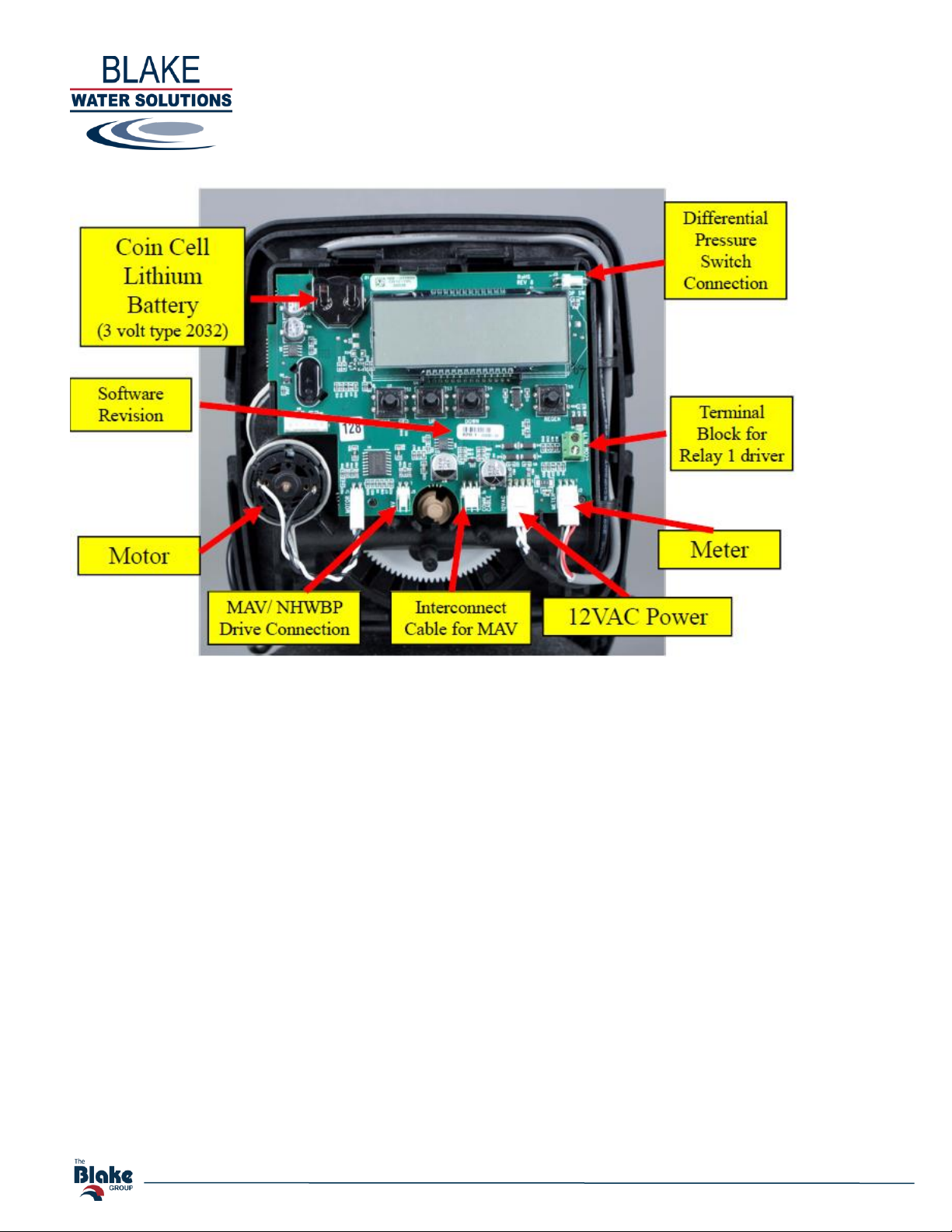
Controller
Control Operation During Service
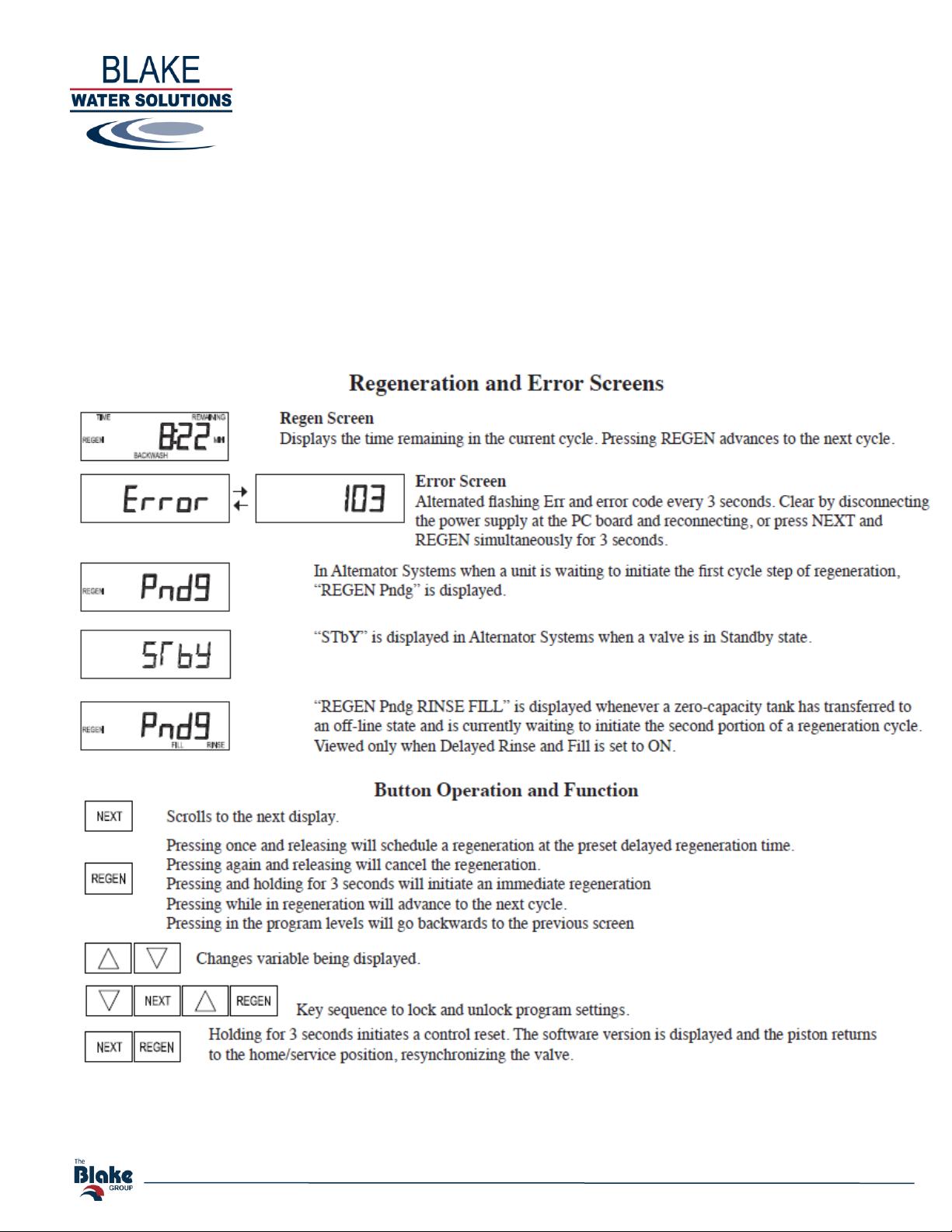
One of five displays is shown. Pressing NEXT alternates between displays.
User 1 - Displays gallons until backwash (not shown if set for time-clock operation).
User 2 - Displays number of days until next backwash.
User 3 - Displays present flow rate in gallons per minute (always reads 0 because no meter is installed).
User 4 - Displays total volume in gallons since last reset (always reads 0 because no meter is installed).
User 5 - Shows current time.
7 of 11
Integrity Excellence Teamwork Innovation
Control Operation during Backwash / Regeneration
During regeneration, the control displays the time remaining in the step that the valve is either advancing to, or has reached. The
step time flashes until the valve completes driving to that step. Once all steps are complete the valve returns to service / normal
operation. Pressing the REGEN button during regeneration advances the valve to the next step.
Control Operation during Programming
The control can only enter the Programming Mode with the valve in service. While in the Programming Mode, the control
continues to monitor water usage and time. Control programming settings are permanently stored in nonvolatile memory.
Control Operation during a Power Failure
The control valve includes a coin cell backup battery. In the event of power failure, the control shifts into power-saving mode and
stops monitoring water usage. The display and motor shut down, but the control continues to keep track of the time for
approximately 8 hours. System configuration settings are stored indefinitely in non-volatile memory. The Time of Day flashes
after a power failure. Press any button to stop the flashing. Reset time if necessary.
If power fails while the unit is in regeneration, the control will save the current valve position. When power is restored, the control
will resume the regen cycle from the point where power failed. The installation should include all required safety components to
prevent overflows resulting from a power failure during regeneration. The control will not start regeneration cycle without power.
8 of 11
Integrity Excellence Teamwork Innovation
Programming Screens
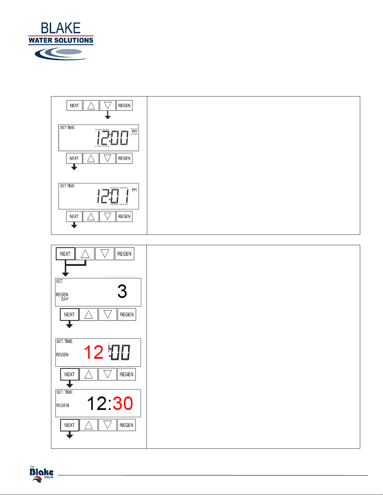
Setting Time of Day
Push NEXT until time of day screen is displayed.
Press and hold ▼ until SET TIME is displayed and the hour flashes.
Press ▲ or ▼ until the correct hour is displayed.
Then press NEXT. The minutes will flash. Press ▲ or ▼ until the
correct minute is displayed.
Press NEXT to return to the User Displays.
In the event of a power outage that is less than 8 hours, the control
valve will remember all settings and time of day.
After 8 hours, the only item that needs to be reset is the time of day
(indicated by the time of day flashing). All other settings are
permanently stored in the control valve’s nonvolatile memory.
If a power loss occurs that is less than 8 hours and the time of day
flashes, this indicates that the battery is depleted. The time of day
should be reset and the non-rechargeable battery should be replaced.
The battery is a 3 Volt Lithium Coin Cell type 2032. Time of day
should be reset when Daylight Savings Time starts / ends.
Installer Settings
To enter Installer Display press NEXT and ▲ simultaneously for
about 5 seconds and release.
Day Override: sets the number of days between regenerations. Set
Day Override using ▲or ▼(1 to 28). Default is 3 Days
Press NEXT to go to step 3I. Press REGEN to return to previous
step.
Regeneration Time (hour): Set the hour of day for regeneration
using ▲or ▼. The default time is 12:30 am.
Press NEXT to go to step 4I. Press REGEN to return to previous
step.
Regeneration Time (minutes): Set the minutes of day for
regeneration using ▲or ▼. The default time is 12:30 am.
Press NEXT to exit Installer Display Settings. Press REGEN to
return to previous step.

9 of 11
Integrity Excellence Teamwork Innovation
System Setup (for reference only –completed during assembly)
Step 1S - Press NEXT and ▼simultaneously for 5 seconds and release.
Step 2S –Leave as default setting = “SOFTENING”.
Press NEXT to go to Step 3S. Press REGEN to exit OEM Softener System Setup.
Step 3S –Leave as default Brining Direction = “dn”.
Press NEXT to go to Step 4S. Press REGEN to return to previous step.
Step 4S –Leave as default Fill = “Post”.
Press NEXT to go to Step 4S. Press REGEN to return to previous step.
Step 5S –Select the time for the first cycle (Backwash) using ▲or ▼.
Default = 10 minutes. INCREASE AS NECESSARY BUT DO NOT DECREASE.
Press NEXT to go to Step 6S. Press REGEN to return to previous step.
Step 6S –Select the time for the second cycle (Air Recharge) using ▲or ▼.
Default = 40 minutes. INCREASE AS NECESSARY BUT DO NOT DECREASE.
The display will flash between cycle number & time, & brine direction (UP or dn).
Press NEXT to go to Step 7S. Press REGEN to return to previous step.
Step 7S –Select the time for the third cycle using ▲or ▼.
Default = “oFF”. DO NOT CHANGE.
Press NEXT to go to Step 8S. Press REGEN to return to previous step.
Step 8S –Select the time for the fourth cycle using ▲or ▼.
Default = “oFF”. DO NOT EXCEED 1 MINUTE.
Press NEXT to go to Step 9S. Press REGEN to return to previous step.
Step 9S –Select the pounds for the fifth cycle using ▲or ▼.
Default = “oFF”. DO NOT CHANGE.
Press NEXT to go to Step 10S. Press REGEN to return to previous step.
Step 10S –Set System Capacity –Leave at Default.
Press NEXT to go to Step 11S. Press REGEN to return to previous step.
Step 11S –Set Volume Capacity –Leave at “oFF”
Regeneration will be triggered by the day override setting, or can be set to regenerate
on specific days of the week.
Press NEXT to go to Step 12S. Press REGEN to return to previous step.
Step 12S –Set Regeneration Trigger using ▲or ▼.
If Step 11S is set to OFF, Regeneration Trigger can be set to 28 day or 7 day.
Press NEXT to go to Step 13S. Press REGEN to return to previous
Step 13S –Not Shown
Step 14S –Set Relay Operation –“oFF”. If set to “oFF”, 15S & 16S are not shown.
Press NEXT to go to Step 15S. Press REGEN to return to previous step.

10 of 11
Integrity Excellence Teamwork Innovation
REPLACEMENT PARTS
Part #
Desc.
Photo (not to scale)
KT7704AIO
WS1EE AIO Valve
K74V3005
STACK
K74V3011
PISTON
K74V3174
REGENERANT PISTON
OV32
INLET CHECK VALVE
OV15HT
AIR DRAW CHECK VALVE
H6061
AIR DRAW SCREEN
KTSCREEN
SCREEN W/ TUBE
K74V4144AIO
AIR DRAW ASSY COMPLETE
AIOGROM
GROMMET
D7147
UPPER DEFLECTOR
K74V30101F*
INJECTOR F (BLUE)
RKWS1AIO
AERATION MAINTANANCE KIT
Includes Blue Injector, Pistons, Stack Assy, Stack
Puller Tool, and Service Wrench
VARIES
DRAIN LINE FLOW CONTROL
~
*Injector may vary on larger tanks
11 of 11
Integrity Excellence Teamwork Innovation
FILTRATION MEDIA OVERVIEW
Media
Physical Characteristics
Description
Birm®
Color: black
Density: 40 –45 lbs. per CF
Mesh size: 10 x 50
Birm® is a granular, silica based, manganese dioxide coated, filter media commonly used for the
reduction of iron and/or manganese from water supplies. It acts as an insoluble catalyst to
enhance the oxidation reaction between dissolved oxygen in the water and the iron and
manganese compounds. The oxidized minerals are precipitated out of solution and removed by
filtration in the bed. Birm offers long material life with relatively low attrition loss, a wide
temperature performance range and extremely high removal efficiency. Regeneration is not
required. Certified to NSF/ANSI Standard 61.
BWS™
Aeration Mix
Color: black / brown / whitish
Density: 45 lbs. per CF
BWS Aeration Mix is a custom media blend for use with Aeration Iron Oxidizing (AIO) filters for
the reduction of iron and/or manganese from water supplies. It consists of a proprietary mixture
of Birm®, Calcite®, Corosex® and Filter Ag® medias for pH correction, oxidation acceleration,
and particle filtration in a single media tank. Due to the sacrificial nature of both Calcite and
Corosex, periodic replenishment will be required. Birm and Filter Ag are durable minerals with a
life expectancy of 8-10 years.
Calcite
Georgia
Marble
Color: whitish
Density: 100 lbs. per CF
Mesh size: 16 x 40
CaCO3: 95% min
MgCO3: 3.0% max
Calcite is a naturally occurring, crushed and screened white marble media which is used to
neutralize acidic or low pH waters to a neutral, less corrosive state. Upon contact with Calcite,
acidic waters slowly dissolve the calcium carbonate to raise the pH which reduces the potential
leaching of copper, lead and other metals found in typical plumbing systems. Calcite corrects pH
only enough to reach a non-corrosive equilibrium. It does not overcorrect under normal
conditions. Periodic backwashing will prevent packing, reclassify the bed and maintain high
service rates. The media will have to be periodically replenished as the Calcite is depleted. As
the Calcite’s calcium carbonate neutralizes the water, it will increase hardness and a softener
may become necessary after the neutralizing filter. Certified to NSF/ANSI Standard 61.
CENTAUR®
Catalytic
Activated
Carbon
Color: black
Density: 34 lbs. per CF
Mesh size: 12 x 40
CENTAUR is engineered carbon with enhanced catalytic properties to accelerate and promote
oxidation, reduction, decomposition, substitution reactions for the elimination of chloramines,
hydrogen sulfide and iron from drinking water. Advantages include low water-soluble ash content,
wide pH operating range, and it is not impregnated with metals or alkali, eliminating safety
concerns. Certified to NSF/ANSI Standard 42.
Chemsorb®
Color: light green
Density: 55 lbs. per CF
Mesh size: 14 x 40
Chemsorb is a natural Zeolite mineral with a highly porous granular surface area that provides
superior filtration down to 5 micron at high flows up to 12-18 gpm/ft². Advantages include the
removal of a wide range of colloidal and soluble inorganic contaminants by surface sorption,
chemical-binding, charge-neutralization, coagulation reactions, and/or ion-exchange phenomena.
Certified to NSF/ANSI Standard 61.
Corosex®
Color: brownish white
Density: 75 lbs. per CF
Mesh size: 6 x 16
Corosex® is a specially processed hard, bead-like magnesium oxide media, adapted for use in
filters to neutralize acidity by increasing the pH value. Corosex neutralizes free carbon dioxide in
water correcting acidic conditions and rendering it less corrosive. Corosex is a highly reactive
magnesium oxide and is most effective where pH correction is substantial or high flows are
required. Under certain low flow conditions, Corosex may over correct and create a highly basic
(high pH) condition. As Corosex’s neutralizes the water, it will increase hardness and a softener
may become necessary after the neutralizing filter. Certified to NSF/ANSI Standard 61.
Filter-AG®
Color: light gray to whitish
Density: 24 - 26 lbs. per CF
Mesh size: 10 x 34
Filter-AG is a granular pumicite media with a fractured and highly irregular surface area. This
unique structure creates a complex flow path allowing for maximum removal of suspended matter
throughout the filter bed. It typically removes suspended solids down to 20 –40 microns. Filter-
AG’s larger particle size creates less pressure loss and high dirt removal capacity resulting in
longer filter runs. Due to this and its lighter weight, it works very well in dual bed or multi-media
filtration systems (in addition to single beds). Certified to NSF/ANSI Standard 61.
Katalox
Light®
Color: black
Density: 66 lbs. per CF
Mesh size: 14 x 30
Katalox-Light® is an engineered catalytic ZEOSORB media coated with manganese dioxide. It is
used for high level filtration, color and odor removal, Iron, Manganese, Hydrogen sulfide removal,
and pH correction. Under certain conditions, an oxidizer such as H2O2may be used to accelerate
the catalytic oxidation on the surface of the media. Certified to NSF/ANSI Standard 61.
Greensand
Plus™
Color: black
Density: 85 lbs. per CF
Mesh size: 18 x 60
GreensandPlus™ is a granular, silica based, manganese dioxide coated, filter media commonly
used for the removal of soluble iron, manganese and hydrogen sulfide from well water. The
manganese dioxide coating acts as a catalyst in the oxidation reaction of iron and manganese.
Chemical regeneration is necessary. Depending on the application, regeneration may be
continuous (CR) or intermittent (IR). Certified to NSF/ANSI Standard 61.
MTM®
Color: dark brown
Density: 45 - 50 lbs. per CF
Mesh size: 12 x 50
MTM is a granular manganese dioxide filtering media used for reducing iron, manganese and
hydrogen sulfide from water. Its active surface coating oxidizes and precipitates soluble iron and
manganese. Hydrogen sulfide is oxidized to sulfur. The precipitates are then filtered out in the
granular bed and removed by backwashing. Chemical regeneration is necessary. Depending on
application, regeneration may be continuous or intermittent. Certified to NSF/ANSI Standard 61.

NOTES:

NOTES:

GROUP
The
Blake
GROUP
The
Blake
Serving New England, New York, Long Island,
Northern New Jersey and Northeastern Pennsylvania
RHODE ISLAND
VERMONT
BLAKE EQUIPMENT
RUTLAND
280 Quality Lane
Rutland, VT 05701
Phone: (800) 643-7100
MASSACHUSETTS
BLAKE EQUIPMENT
GREENFIELD
28 Butternut Street
Greeneld, MA 01301
Phone: (800) 628-1998
NEW HAMPSHIRE
BLAKE EQUIPMENT
CONCORD
34 Locke Road #5
Concord, NH 03301
Phone: (800) 552-0389
CONNECTICUT
THE BLAKE GROUP
Headquarters
4 New Park Road
East Windsor, CT
Phone: (800) 353-1100
BLAKE EQUIPMENT
EAST WINDSOR
6 New Park Road
East Windsor, CT 06088
Phone: (800) 593-7867
BLAKE EQUIPMENT
DANBURY
34 Executive Drive
Danbury, CT 06810
Phone: (800) 791-7867
MAINE
BLAKE EQUIPMENT
HERMON
1194 Odlin Road
Hermon, ME 04401
Phone: (800) 450-6822
BLAKE EQUIPMENT
PORTLAND
70 Ingersoll Drive Unit #1
Portland, ME 04103
Phone: (800) 308-2213
The Blake Group is a growing family of companies dedicated to providing our valued customers with
superior products and technologies in commercial, industrial, and residential markets, compliant with
industry standards and meeting all facets of our customers’ expectations.
BLAKE EQUIPMENT
EAST SYRACUSE
6059 Corporate Drive
East Syracuse, NY 13057
Phone: (800) 792-2346
NEW YORK
BLAKE EQUIPMENT
ONEONTA
Route 23 Southside
Oneonta, NY 13820
Phone: (800) 336-6611
BLAKE EQUIPMENT
PINE ISLAND
76 Skinner Lane
Pine Island, NY 10969
Phone: (800) 914-0099
BLAKE EQUIPMENT
ALBANY
13 Thatcher Street
Albany, NY 12207
Phone: (518) 465-0713
BLAKE EQUIPMENT
PASCOAG
222 Davis Drive
Pascoag, RI 02859
Phone: (800) 869-7677
This manual suits for next models
1
Table of contents
Popular Water Filtration System manuals by other brands

US Water Systems
US Water Systems Oxi-Gen 150-MO-1 Installation, operation and maintenance manual

FSI
FSI x100 Operator's guide

Pentair
Pentair 1.0 Service manual

TMC Aquarium
TMC Aquarium V2Bio 600 Instructions for installation and use

Blagdon
Blagdon Inpond 5 in 1 2000 manual

Watts
Watts WH-VIH1-SED-A-WHT-HSG Installation, operation and maintenance manual

RAINSHOWER
RAINSHOWER REFRESH Instruction guide

Wrekin Water
Wrekin Water SS15 Installation and operating instructions

SuperFish
SuperFish Pond Clear UVC 30000 user manual

EasyPro
EasyPro Eco-Clear EC2600 Instructions for Operation, Safety, Warranty

BWT
BWT Quick & Clean instruction manual

Oase
Oase FiltoClear 5000 manual


