Oneida Air Systems Dust Deputy Low-Pro Plus AXD259911 Installation manual

Rev: C 20240105LL Doc. # ZBM000053
English
Appearance may vary slightly
Dust Deputy Low-Pro™
Lid Separator
Plus
# AXD259911
Patents: www.oneida-air.com/patents
Start-Up Information
1. DO NOT use to pick up anything that is burning or smoking, such as cigarettes, matches, or hot ashes.
2. DO NOT collect ammable or combustible liquids, gases, or explosive dusts, such as gasoline or other fuels, lighter uid, cleaners, oil-based paints, natural gas,
hydrogen, coal dust, magnesium dust, grain dust, aluminum dust, sugar dust, our dust or gun powder.
3. Can be used for collecting non-ammable liquids.
4. DO NOT use or store near hazardous materials.
5. DO NOT operate in areas where explosion risks are high. Areas of high risk include, but are not limited to, areas near pilot lights, open ames, or other ignition
sources.
6. ALWAYS wear a NIOSH approved respirator when emptying dust bins and during operation. Dust created by machinery operations may cause cancer, birth defects,
or long-term respiratory damage. Be aware of dust hazards associated with each work piece material.
7. NEVER introduce sparks or sources of ignition.
8. ENSURE all equipment and connections are electrically grounded.
9. ONLY operate in locations that has a re extinguisher available nearby.
10. ALWAYS dispose of waste in a re safe area aer each use. NEVER leave wood dust in a building or vehicle. Wood dust mixtures are highly ammable and can be
explosive.
READ THE SAFETY PRACTICES, INSTALLATION AND MAINTENANCE INSTRUCTIONS, AND YOUR WET/DRY
VACUUM’S OWNER’S MANUAL BEFORE ASSEMBLING AND USING THE DUST DEPUTY.
SOME DUSTS ARE HIGHLY FLAMMABLE OR EXPLOSIVE. LEARN/ KNOW WHAT YOU ARE DEALING WITH. FOLLOW
ALL LOCAL, STATE, FEDERAL & NFPA CODES AND GUIDELINES.
18-1/2"
470 mm
5-1/16"
129 mm
3-13/16"
98 mm
Nominal dimensions shown. Dimensions subject to slight variations in manufacturing.
12-3/8"
315 mm
As installed on a
5 Gallons
19 Liters
Bucket
Dimensions

BB
Correct Installation
Gasket connects; Ends
firmly butt up against
each other.
Incorrect Installation
Gasket does not connect;
Gap between the ends.
Inside Outside
ID Part number Part description Qty
A SDL250000 Lid Separator 1
B RGZ000005 5/8 x 40" Gasket 1
C AHX000035 Latch Hardware Pack 2
C1 AFS000016SS #8 x 5/8" Thread Cutting Screw 1
C2 AFW041010 Flat Washer 1
C3 AFL000009 Latch 1
D AXD000031 2.5" x 36" Hose 1
E AHA000004 2.5" Elbow 1
F VFA050015 Metal Grounding Tape 30"
Assembly Instructions
You will need the following:
• Phillips Head Screwdriver
• Bucket
• Scissors / Razor Blade
• Wet/Dry Vacuum
• Vacuum hose and adapters
(2.5" recommended)
1. Apply the 5/8" Gasket (B) onto the Lid
Separator (A) along the underside of the rim's
circumference [FIG. 1a & 1b].
Note: e Gasket ends should rmly butt up
against each other to avoid air leaks [FIG. 1b].
Dust collection systems cannot operate eectively if
there isn’t a complete seal [FIG. 1c]. ere must be
NO air leaks.
2. Secure each Latch (C3) to the Lid Separator (A)
using one Washer (C2), and one Screw (C1) as
shown in [FIG. 2].
Note: Refer to the Optional Grounding Instructions
section prior to this step if necessary.
FIG. 2
System Contents
C1 C2 C3
BA
C
D
F
E
C3
C2
C1
1-800-732-4065
A
FIG. 1b
FIG. 1a
FIG. 1c
B

Leak Point
(Inlet)
Leak Point
(Low-Pro/
bucket)
Leak Point
(Outlet)
Inward Outward
To Tool
To vacuum
Assembly Instructions Assembly Instructions
Optional Grounding Instructions
3. Simultaneously pull the Latches (C3) outward
and snap the Low-Pro assembly rmly down onto
your bucket so that the gasket is compressed.
en push the Latches inward and ensure that
they are under the lip of the bucket [FIG. 3]. e
latch Screw (C1) can be adjusted to better tighten
the latches to the lip of the bucket.
Note: It's normal for the Low-Pro to t loosely but
it will seal rmly shut under vacuum pressure.
4. Connect the Low-Pro's (A) top outlet port to your
vacuum with Hose (D) and Elbow (E) as shown
in [FIG. 3].
Connect the Low-Pro's side inlet port to your
tool with your vacuum's hose [FIG. 3].
Note: Both ports accept standard 2.5" hose cus
(OD ≈ 2.25").
5. Review [FIG. 5] for common air leak points.
To empty your bucket, li up on the Latches (C3)
and li up the Low-Pro Assembly.
Installation is complete!
Note: Any air leak will aect separation
performance. Make sure to check your dust drum
frequently so you do not overll it.
6. Install the Metal Tape (F) to the Lid Separator (A)
so that the inlet, outlet, and ange are attached by
a continuous, conductive path as shown in [FIG
6a]. e Metal Tape should wrap 1/4" around the
edge of each opening.
Note: For added grounding, attach a self-
supplied wire with a ring terminal on one
end and a washer tied to the other end when
installing one of the latches in step 2. e wire
must be long enough for the washer to lie on the
oor [FIG 6b].
FIG. 4
FIG. 3
FIG. 5
FIG. 6a
FIG. 6b
E
D
F
Recommended for fine dust situations or
electronically sensitive applications.
Washer
Wire
oneida-air.com

For full warranty terms and conditions please visit oneida-air.com/warranty. Oneida Air Systems warrants this product for a period of 1 Year, to the original purchaser
from the date of purchase unless otherwise specied. Purchaser is responsible for returning warranty items to Oneida Air Systems at their expense. All parts must be
returned with an Oneida Air Systems provided Returned Material Authorization Number (RMA#). Any shipment without an RMA will be refused.
Review the included document "Additional Troubleshooting" (ZBI000072)
for further clarication.
Scan here or visit: oneida-air.com/lowes-dust-deputy-low-pro
for more tips, videos, demos, and more!
Customer Service Department
1-866-387-8822 • support@oneida-air.com
1001 West Fayette Street, Syracuse, NY 13204 U.S.A.
Copyright © 2024 Oneida Air Systems, Inc.
ank you for your purchase of this American made product!
Regardless of where you purchased your Oneida Air Systems' product, if you have any questions or issues with
missing / damaged parts, please call us rst to let us help resolve your problem. We fully stand behind the quality
of our products and place the utmost value on the satisfaction of our customers.
We want to do everything possible to make your purchase and experience with Oneida Air Systems a good one!
Limited Warranty Information
Troubleshooting

Rev: C 20240105LL Doc. # ZBM000053
Spanish
La apariencia puede variar ligeramente
Dust Deputy Low-Pro™
Tapa Separadora
Plus
# AXD259911
Patentes : www.oneida-air.com/patents
Información de Inicio
1. NO utilice para recoger nada que esté ardiendo o humeando, como cigarrillos, cerillas, o cenizas calientes.
2. NO recolecte líquidos, gases, o polvos explosivos inamables o combustibles, como gasolina o otros combustibles, líquido de encendedor, limpiadoras, pinturas a
base de aceite, gas natural, hidrógeno, polvo de carbón, polvo de magnesio, polvo de grano, polvo de aluminio, polvo de azúcar, polvo de harina, o pólvora.
3. Se puede utilizar para recoger líquidos no inamables.
4. NO utilice ni almacene cerca de materiales peligrosos.
5. NO opere en áreas donde los riesgos de explosión sean altos. Áreas de riesgo alto incluyen, pero no se limitan a, áreas cerca de las luces piloto, llamas abiertas, u
otras fuentes de ignición.
6. SIEMPRE lleve un respirador aprobado por NIOSH al vaciar los contenedores de polvo y durante la operación. El polvo creado por las operaciones de la
maquinaria puede causar cáncer, defectos de nacimiento, o daño respiratorio a largo plazo. Esté consciente de los peligros de polvo asociados con cada material de
pieza de trabajo.
7. NUNCA introduzca chispas o fuentes de ignición.
8. ASEGÚRESE de que todos los equipos y conexiones estén conectados a tierra.
9. Únicamente opere en lugares que tengan un extintor de incendios disponible cerca.
10. SIEMPRE deseche los residuos en un área segura contra incendios después de cada uso. NUNCA deje polvo de madera en un edicio o vehículo. Las mezclas de
polvo de madera son muy inamables y pueden resultar explosivas.
LEA LAS PRÁCTICAS DE SEGURIDAD, INSTRUCCIONES DE INSTALACIÓN Y MANTENIMIENTO, Y LEA SU MANUAL
DEL PROPIETARIO DE SU ASPIRADORA HÚMEDA/SECA ANTES DE MONTAR Y UTILIZAR EL DUST DEPUTY
ALGUNOS POLVOS SON MUY INFLAMABLES O EXPLOSIVOS. APRENDE/SABE CON QUÉ ESTÁS LIDIANDO. SIGA
TODOS LOS CÓDIGOS Y DIRECTRICES LOCALES, ESTATALES, FEDERALES Y LOS CÓDIGOS DE NFPA.
18-1/2"
470 mm
5-1/16"
129 mm
3-13/16"
98 mm
Se muestran las dimensiones nominales. Dimensiones sujetas a ligeras variaciones a la fabricación.
12-3/8"
315 mm
Como está instalado
en un balde de
5 Galones
19 litros
Dimensiones

Dentro Externo
BB
Instalación correcta
La junta se conecta;
Termina firmemente
topado uno contra el otro.
Instalación incorrecta
La junta no se conecta;
Espacio entre los
extremos.
Instrucciones de Ensamblaje
1. Aplique la empaquetadora de 5/8 (B) en la tapa
separadora (A) a lo largo del borde inferior como se
muestra en [FIG. 1a & 1b].
Nota: La Empaquetadora debe estar rmemente sellada
a la tapa y debe superponerse alrededor la circunferencia.
NO debe haber fugas de aire para que el sistema de
recolección de polvo funcione correctamente [FIG. 1c].
2. Asegure cada Pestillo (C3) a la Tapa Separadora (A)
usando una Arandela Plana (C2), y un Tornillo de Corte
de Hilo (C1) como se muestra en [FIG. 2].
Nota: Consulte la sección Instrucciones de Conexión a
Tierra Opcionales antes de esto paso si es necesario.
FIG. 2
C3
C2
C1
A
FIG. 1b
FIG. 1a
FIG. 1c
B
ID Part number Part description Qty
A SDL250000 Tapa separadora 1
B RGZ000005 5/8 x 40" Empaquetadora 1
C AHX000035 Paquete de herrajes para pestillos 2
C1 AFS000016SS #8 x 5/8" Tornillo de corte de hilo 1
C2 AFW041010 Arandela Plana 1
C3 AFL000009 Pestillo 1
D AXD000031 2,5" x 36" Manguera 1
E AHA000004 2,5" Codo 1
F VFA050015 Cinta Metálica de Conexión aTierra 30"
You will need the following:
• Phillips Head Screwdriver
• Bucket
• Scissors / Razor Blade
• Wet/Dry Vacuum
• Vacuum hose and adapters
(2.5" recommended)
Contenidos del Sistema
C1 C2 C3
BA
C
D
F
E
1-800-732-4065

Punto de fuga
(Entrada)
Punto de fuga
(Low-Pro/balde)
Punto de fuga
(Salida)
A la herramienta
A la aspiradora
Instrucciones de Ensamblaje
3. Simultáneamente, tire de los pestillos (C3) hacia afuera
y encaje rmemente el conjunto Low-Pro en su balde
para que la junta quede comprimida. Luego empuje los
pestillos hacia adentro y asegúrese de que estén debajo
del borde del balde [FIG. 3]. El tornillo del pestillo (C1)
se puede ajustar para apretar mejor los pestillos al borde
del cucharón.
Nota: Es normal que el Low-Pro quede ojo, pero se
sellará rmemente bajo presión de vacío.
4. Conecte la Tapa Separadora (A) del Low-Pro puerto
de salida superior a su aspiradora con Manguera (D) y
Codo (E) como se muestra en [FIG. 4].
Conecte el puerto de entrada lateral de Low-Pro a su
herramienta con su manguera de aspiradora [FIG. 3].
Nota: Ambos puertos aceptan manguitos de manguera
estándar de 2,5” (OD = 2,25”).
5. Revise [FIG. 5] para puntos comunes de fuga de aire.
Para vaciar su balde, levante los pestillos (C3) y levante
el conjunto Low-Pro.
¡La instalación está completa!
Nota: Cualquiera fuga de aire afectará el rendimiento de
separación. Asegúrese de revisar su tambor de polvo con
frecuencia para no llenarlo demasiado.
FIG. 3
FIG. 5
FIG. 4
E
D
Assembly Instructions
Instrucciones de Conexión a Tierra Opcionales
6. Instale la Cinta Metálica (F) a la Tapa Separadora (A)
para que la entrada, la salida, y la brida están unidos
por un camino conductivo continuo como se muestra
en [FIG. 6a]. La Cinta Metálica debe envolverse ¼"
alrededor del borde de cada abertura.
Nota: Para mayor conexión a tierra, conecte un cable
autoabastecido con un terminal de anillo en un extremo y
una arandela atada a otro extremo al instalar uno de los
pestillos en el paso 2. El cable debe ser lo sucientemente
largo para la arandela estar en el suelo como se muestra
en [FIG. 6b].
FIG. 6a
FIG. 6b
F
Recomendado para situaciones de polvo fino o
aplicaciones electrónicamente sensibles.
Una arandela
Un Cable
oneida-air.com
Inward Outward

Para conocer los términos y condiciones completos de la garantía, favor de visitar oneida-air.com/warranty. Oneida Air Systems garantiza este producto por un período
de un año al comprador original a partir de la fecha de compra, a menos que se especique lo contrario. El comprador es responsable de devolver los artículos en garantía
a Oneida Air Systems a su costa. Todas partes deben devolverse con un Número de Autorización de Devolución de Material (RMA#) proporcionado por Oneida Air
Systems. Cualquier envío sin un Número de Autorización de Devolución de Material (RMA#) será rechazado.
Customer Service Department
1-866-387-8822 • support@oneida-air.com
1001 West Fayette Street, Syracuse, NY 13204 U.S.A.
Copyright © 2024 Oneida Air Systems, Inc.
¡Gracias por comprar este producto fabricado en los Estados Unidos!
Independientemente de dónde haya comprado su producto de Oneida Air Systems, si tiene algunas preguntas
o problemas con piezas faltantes/dañadas, por favor llámenos primero para permitirnos ayudarlo a resolver su
problema. Respaldamos plenamente la calidad de nuestros productos y damos el máximo valor a la satisfacción
de nuestros clientes.
¡Queremos hacer todo lo posible para que su compra y experiencia con Oneida Air Systems sean buenas!
Información de Garantía Limitada
Revise el documento incluido "Solución de problemas adicionales" (ZBI000072) para
obtener más aclaraciones.
¡Escanee aquí o visite: oneida-air.com/lowes-dust-deputy-low-pro
Para más consejos, videos, demostraciones y más!
Solución de Problemas

Additional Troubleshooting
The Dust Deputy Low-Pro pre-separates up to 99.9%
of dust and debris. Our team conducted a stress test and
found after 20 minutes of sanding with a 5-inch palm
sander using 100-grit paper that there was no discernable
dust in the vacuum container or in the pleats of the lter.
If you nd the Dust Deputy Low-Pro is not performing
as shown in [FIG. 1], then follow these additional
troubleshooting steps to x the problem.
1. ere must be NO air leaks. An air leak will cause dust to
bypass the lid separator, leading to a clogged lter, and the
nest particles will pass through rst.
Check to make sure your setup has no air leaks or gaps
[FIG. 2]. Dust collection systems cannot operate eectively
if there isn’t a completely airtight seal. e most common
leak is between the lid separator and the rim of the bucket.
2. Make sure that the gasket is in good condition with no
cracks or tears and is installed with the ends rmly butted
up against each other as shown in [FIG. 3a]. Proper sealing
prevents dust and air from escaping [FIG. 3b]. Replace the
gasket if it is worn or torn.
Leak Point
(Low-Pro/bucket)
FIG. 3a
FIG. 3b
FIG. 2
FIG. 1
Correct Installation
Gasket connects; Ends
firmly butt up against
each other.
Incorrect Installation
Gasket doesn't connect;
Gap between the ends.
Rev: B 20240103LL Doc. #ZBI000072

Contact our Customer Service Department for further assistance
1-866-387-8822 • support@oneida-air.com • oneida-air.com/contact-us
1001 West Fayette Street, Syracuse, NY 13204 U.S.A. • Copyright © 2024
Oneida Air Systems, Inc.
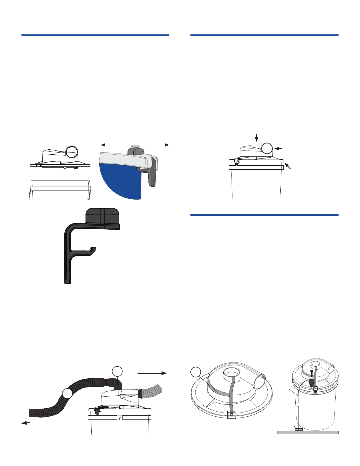
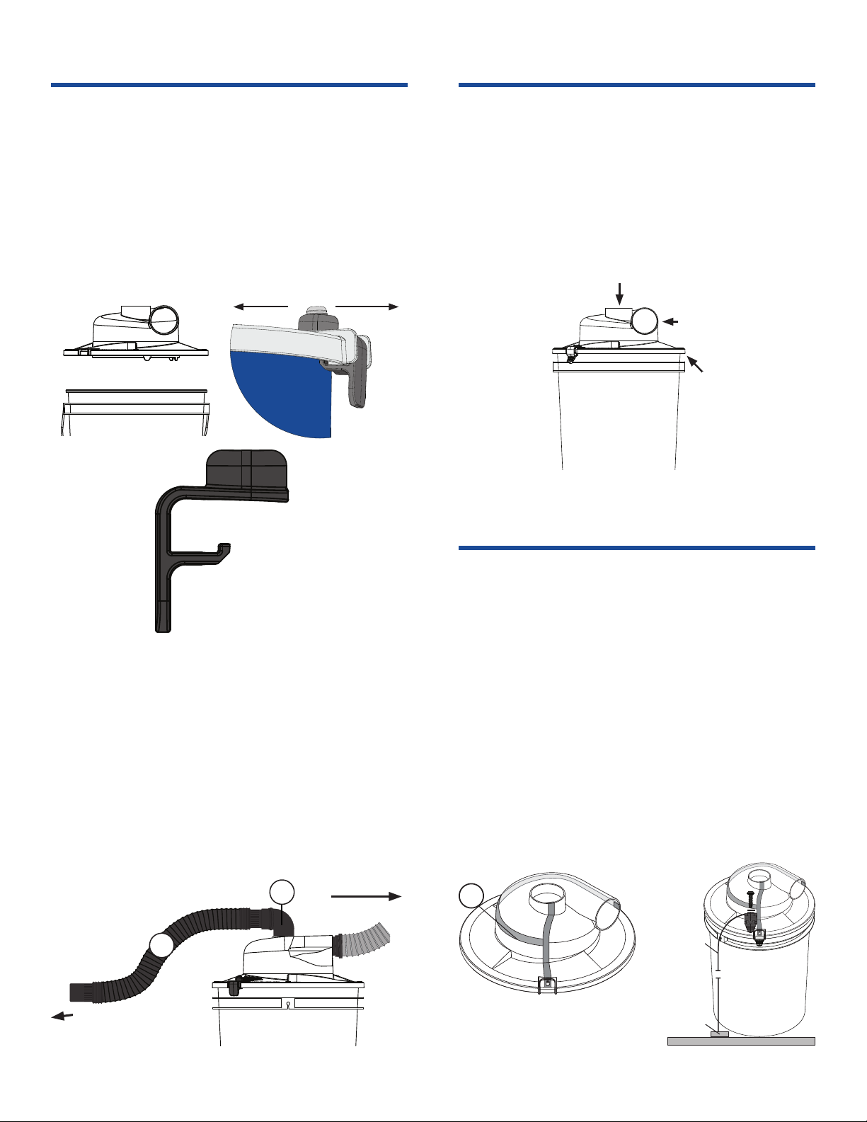
3. e Dust Deputy Low-Pro’s adjustable latches t a
wide variety of buckets, some of which may give a false
impression that they are fully secured and airtight.
a. Li up on both the latches simultaneously and push the
Low-Pro rmly down onto the bucket so that the gasket
is compressed. en push the latches inward and ensure
that they are closed under the lip of the bucket [FIG.
4]. e latch screw can be adjusted to better tighten the
latches to the lip of the bucket.
b. If your Dust Deputy Low-Pro’s latches are the older
rubber-wire hold down style, rather than the new
molded plastic style, please contact Oneida Air Systems’
Customer Service Department at 1-866-387-8822
or support@oneida-air.com and we will send out an
upgrade clip free of charge.
If you are condent your Dust Deputy Low-Pro is sealed
airtight to your bucket, yet you are still experiencing poor
separation, then please check the following:
4. Ensure your Dust Deputy Low-Pro model has the central
Plug installed [FIG. 5]. If your model is missing the Plug,
please contact Oneida Air Systems’ Customer Service
Department at 1-866-387-8822 or support@oneida-air.com
and we will send out a replacement free of charge.
5. Over time the bucket’s rim may become damaged, aecting
the seal and in turn the performance. Replace your bucket.
6. Use either a shorter length hose or a larger diameter (2.5"
max.) hose which will increase airow (CFM) through the
cyclone. Increased airow also increases air velocity in the
cyclone and improves separation eciency.
7. Proper lter cleaning and replacement should not be
neglected. Replace your lter if there is a buildup of dust and
it has become less permeable thus restricting airow.
Latched under the lip
FIG. 4
Plug
FIG. 5
Rev: B 20240103LL Doc. #ZBI000072
Table of contents
Languages:
Other Oneida Air Systems Water Filtration System manuals

Oneida Air Systems
Oneida Air Systems Dust Deputy 2.5 D.I.Y. User manual

Oneida Air Systems
Oneida Air Systems Dust Deputy Plus AXD050004 User manual

Oneida Air Systems
Oneida Air Systems Dust Deputy D.I.Y. User manual

Oneida Air Systems
Oneida Air Systems Dust Deputy Low-Pro Plus User manual

Oneida Air Systems
Oneida Air Systems Deluxe Dust Deputy User manual

Oneida Air Systems
Oneida Air Systems AXD002030AXL User manual