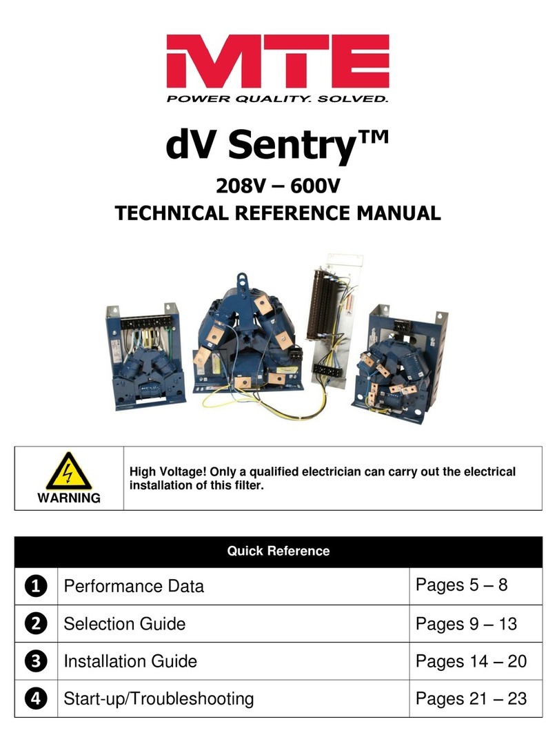
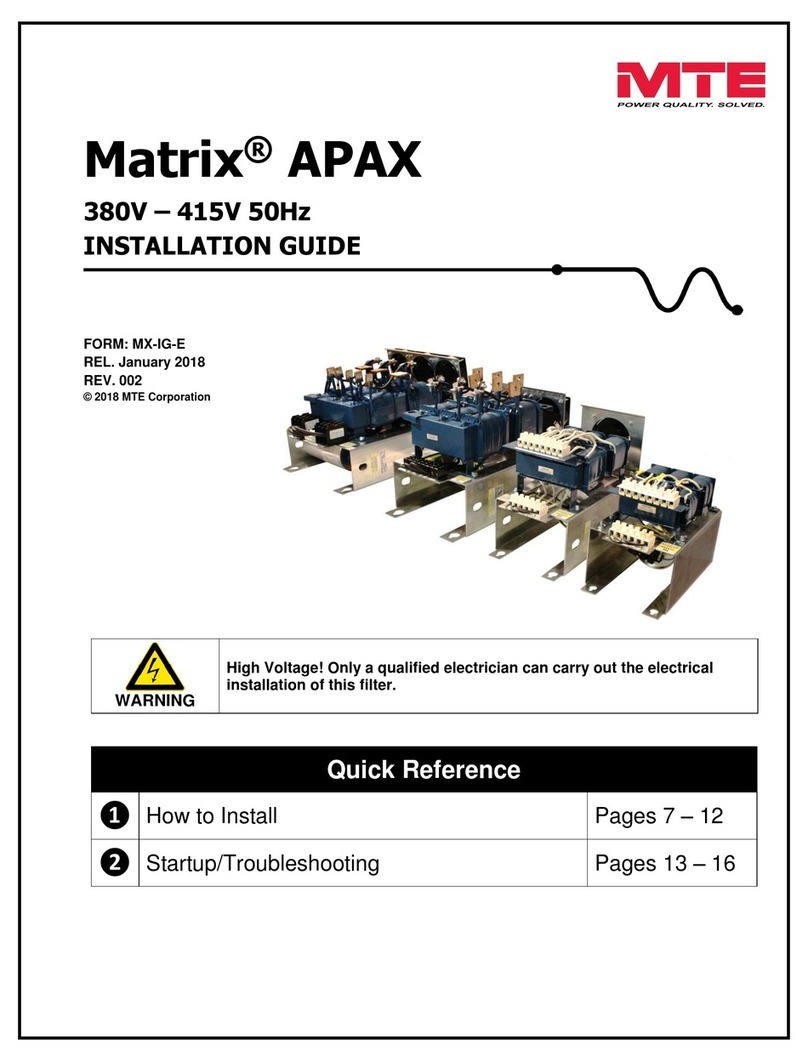
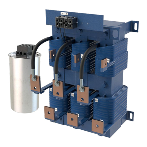
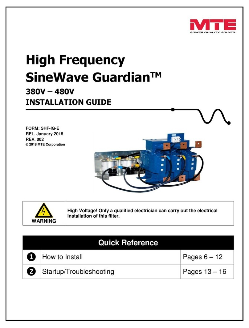
MTE MATRIX FILTER A Series User manual

©2000MTECorporation
PARTNO. INSTR -002
REL. 060607
MTECorporation
MATRIXFILTER
SERIESA
480Volts60Hz
USER MANUAL
PDFcreated withpdfFactorytrialversion www.pdffactory.com

PDFcreated withpdfFactorytrialversion www.pdffactory.com

IMPORTANTUSERINFORMATION
NOTICE
The MTECorporation MatrixFilterisdesigned forharmonicmitigationof six
pulseinverterdrivessupplyingvariabletorqueloadsinawidevarietyof
applications. The suitabilityof thisfilterforaspecificapplication must
thereforebedetermined bythe customer. Inno event willMTECorporation
assumeresponsibilityorliabilityforanydirectorconsequentialdamages
resulting fromthe useorapplication ofthisfilter. NorwillMTECorporation
assumepatent liabilitywithrespect totheuseof information, circuitsor
equipment described inthisinstructionmanual.
PDFcreated withpdfFactorytrialversion www.pdffactory.com

PDFcreated withpdfFactorytrialversion www.pdffactory.com

TABLEOFCONTENTS
1.Safety..........................................................................................................1
2.Introduction .................................................................................................3
3.ModelNumberCodes..................................................................................4
4.Specifications..............................................................................................5
Ratings.......................................................................................................5
ServiceConditions.....................................................................................5
Performance...............................................................................................6
Altitude Derating Curve............................................................................10
5.Installation Instructions.............................................................................11
FilterInstallation.......................................................................................11
PowerWiringConnection.........................................................................11
Ground and Ground Fault Protection.........................................................12
Inputand OutputTerminalSpecifications.................................................12
OutlineDrawingsand MountingDimensions............................................13
Interconnection Diagrams..........................................................................23
6.FilterDescription .......................................................................................26
7.Start –Up..................................................................................................28
8.Troubleshooting.........................................................................................29
8.AddendumA..............................................................................................33
PDFcreated withpdfFactorytrialversion www.pdffactory.com

1
1. IMPORTANTSAFETYINFORMATION
WARNING
ONLYAQUALIFIEDELECTRICIANCANCARRYOUTTHEELECTRICAL
INSTALLATIONOFTHISFILTER
WARNING
High voltage isused intheoperation of thisfilter. UseExtremecaution toavoid
contact withhighvoltagewhen operating,installing orrepairingthisfilter. INJURY
ORDEATHMAYRESULTIFSAFETYPRECAUTIONSARENOTOBSERVED.
Afterremoving power, allowatleast fiveminutestoelapseand verifythat the
capacitorshavedischargedtoasafelevelbeforecontacting internalcomponents.
Connect aDC voltmeteracrossthe capacitorterminals1, 2and3on terminalblock
1TB. Start withthe meteron the highest scaleand progressivelyswitchtoalower
scaleasthe indicated voltage fallsbelowthe maximumvalue ofthe scaleused.
WARNING
The opening of thebranchcircuit protectivedevicemaybeanindicationthatafault current
hasbeeninterrupted. Toreducetherisk offireorelectricalshock, current-carryingpartsand
othercomponentsofthefiltershouldbeexamined andreplacedifdamaged.
WARNING
Anupstreamdisconnect/protectiondevicemustbeusedasrequiredbytheNational
ElectricalCode(NEC).
WARNING
Eveniftheupstreamdisconnect/protectiondeviceisopen, thedrivedownstreamof thefilter
mayfeedback highvoltage tothefilter. Thedrivesafetyinstructionsmustbefollowed.
INJURYORDEATHMAYRESULTIFTHEDRIVESAFETYPRECAUTIONSARE
NOTOBSERVED.
PDFcreated withpdfFactorytrialversion www.pdffactory.com

2
WARNING
The filtermust begroundedwithagroundingconductorconnectedtoall groundingterminals.
WARNING
OnlysparepartsobtainedfromMTECorporation oranauthorizedMTEdistributorcanbe
used.
PDFcreated withpdfFactorytrialversion www.pdffactory.com

3
2. INTRODUCTION
Thismanualwasspecificallydevelopedto
assist inthe installation, interconnection
andoperationof theMTECorporation
MatrixFilter.
Thismanualisintendedforuseby
personnelexperiencedintheoperationand
maintenanceof electronicdrives.Because
ofthehighvoltagesrequiredbythe filter
anddriveandthepotentialdangers
presented byrotatingmachinery, it is
essentialthatall personnelinvolvedinthe
operationandmaintenanceof thisfilter
knowandpracticethe necessarysafety
precautionsforthistypeof equipment.
Personnelshouldreadandunderstand the
instructionscontainedinthismanualbefore
installing,operating orservicing thefilter
andthe drivetowhichthefilteris
connected.
UponReceiptofthisFilter:
The MTEMatrixFilterhasbeensubjected
todemandingfactorytestsbeforeshipment.
Carefullyinspecttheshippingcontainerfor
damagethat mayhave
occurredintransit. Thenunpackthefilter
andcarefullyinspect foranysignsof
damage. Savethe shippingcontainerfor
futuretransportof thefilter.
Intheeventofdamage, please contact
and fileaclaimwiththefreightcarrier
involvedimmediately.
Ifthe equipmentisnotgoingtobeput into
serviceupon receipt, coverand storethe
filterinaclean,drylocation.Afterstorage,
ensurethat theequipment isdryand that
no condensationhasaccumulatedonthe
internalcomponentsof thefilterbefore
applyingpower.
Repair/ExchangeProcedure
MTECorporation requiresaReturned
MaterialAuthorizationNumberbeforeit can
acceptanyfiltersthatqualifyforreturnor
repair. Ifproblemsorquestionsariseduring
installation, setup,oroperationofthefilter,
pleasecall usforassistanceat:
Phone:262-253-8200
FAX:262-253-8222
PDFcreated withpdfFactorytrialversion www.pdffactory.com

4
3. MODELNUMBERCODES
StandardseriesAmodelnumbercodesareofthe formMA-BCDEFG-XY withthe
numbercoded asoutlined below.
Character
Description Code
M Always MforMatrixFilter
A Designatesnumberofinput phases 1Singlephase
3 Three phase
B CharactersBthrough EdesignatetheExample: 0075 isa75 Hpfilter
C Horsepowerratingof thefilterusing
D fourdigitswithleading zeros
E
F Indicatesmechanicalconfiguration NNema1
RReactivecomponentsonly
MMagneticcomponentsonly
PPanelmounted
WWeatherproof
DDust tight
HHosedown
G Designatesinput voltageand frequency A208-240v/ 60Hz
B240 v/ 50Hz
C380-415 v/ 50Hz
D480 v/ 60Hz
E600 v/ 60Hz
F690 v/ 50 Hz
G 690 v/ 60 Hz
H120 v/ 60Hz
J
K
L277 v/60Hz
XY Designatesfilterguaranteed harmonic12 is12%THID
currentperformance 8 is8%THID
PDFcreated withpdfFactorytrialversion www.pdffactory.com

5
4. SPECIFICATIONS
Ratings
480VACThreePhaseInputFilterRatings
(PanelMounted)*
THIDRating 12% 8%
HP
Maximum
Input
Amps
RMS
Maximum
Output
Amps
RMS
Efficiency
(Typical)
(%)
Power
Dissipation
@Rated
HP
(Typical)
(Watts)
Weight
(lbs)
Efficiency
(Typical)
(%)
Power
Dissipation
@RatedHP
(Typical)
(Watts)
Weight
(lbs)
3 6 6 97 47 27 98 40 37
5 9 10 98 66 35 98 63 42
7.5 13 14 98 98 35 98 98 42
10 16 18 98 114 45 98 108 60
15 24 27 98 166 50 98 170 75
20 31 34 98 204 85 98 212 100
25 39 43 98 275 85 98 257 100
30 46 51 98 295 105 98 323 130
40 60 66 98 390 125 98 374 155
50 75 82 98 475 150 98 506 190
60 89 97 98 586 150 98 584 190
75 110 121 98 659 200 98 655 250
100 143 157 98 837 215 98 838 280
125 179 197 98 971 250 98 1051 305
150 207 228 99 1018 275 99 1057 340
200 276 304 98 1521 380 98 1775 600
250 347 382 99 1767 450 98 1889 675
300 415 457 99 1994 575 99 2099 750
*RefertoAddendumAforEnclosed CurrentRatings
ServiceConditions
Load:6pulsevariabletorquerectifieronly
Input voltage:480VAC+/-10%,60+ 0.75Hz,3phase
Input voltagelineunbalance: 1%maximum
Maximumsourceimpedance:6.00%
Minimumsourceimpedance:1.5%
ServiceFactor: 1.00
PDFcreated withpdfFactorytrialversion www.pdffactory.com

6
SPECIFICATIONS–continued
AmbientTemperature
Operating:-40to+50 degreesC(panelmounted construction)
Storage: -40 to+90 degreesC
Altitude: 0to3300 Feetabovesea level. RefertoFigure1foraltitude derating.
RelativeHumidity:0to95% non-condensing
AgencyApprovals
UL-508 FileE180243 Component Recognized
(3-1000 HP, 120 VACthrough 600 VAC
50, 50/60, 60 HZThree Phases
CAN/CSAC22, 2No. 14-95
Performance
Total HarmonicCurrent Distortion:
Standard: 12% maximumno load tofullload
Optional:8% maximumno load tofullload
StandbyCurrent:
WithoutOptionalCapacitorContactor:RefertoTable1
WithOptionalCapacitorContactor:RefertoDriveUsersManual
12% FilterVoltage Regulation withnominal480 voltsRMS source
Maximumoutputvoltage at no load: 502 voltsRMS, 710voltspeak
MaximumPCC* voltage with6.00% sourceimpedanceat no load: 490 voltsRMS,693 voltspeak
Minimumoutputvoltage at fullload: 460 voltsRMS, 600voltspeak
8% FilterVoltage Regulation withnominal480 voltsRMS source
Maximumoutputvoltage at no load: 502 voltsRMS, 710voltspeak
MaximumPCC voltage with6.00% sourceimpedanceat no load: 490 voltsRMS,693 voltspeak
Minimumoutputvoltage at fullload: 460 voltsRMS, 600voltspeak
*Note: PCC isthe point of common coupling withthe powerdistribution system
PDFcreated withpdfFactorytrialversion www.pdffactory.com

7
SPECIFICATIONS-continued
Table1. 480VACThree Phase InputFilters
StandbyCurrentRatingsWithoutOptional CapacitorContactor
HP
Standby
Current
(Typical)
Amps
RMS
HP Standby
Current
(Typical)
Amps
RMS
HP
Standby
Current
(Typical)
Amps
RMS
3 1.7 25 11.0 100 41.0
5 2.3 30 16.0 125 64.0
7-1/2 4.0 40 16.0 150 81.0
10 4.5 50 23.0 200 101.0
15 7.9 60 23.0 250 121.0
20 11.0 75 27.0 300 148.0
12%Filter THD vs Load
0
2
4
6
8
10
12
020 40 60 80 100
PercentLoad
Percent THD
Typical WorstCase
8% Filter THD vsLoad
0
1
2
3
4
5
6
7
8
9
020 40 60 80 100
PercentLoad
Percent THD
Typical Worst Case
PDFcreated withpdfFactorytrialversion www.pdffactory.com

8
SPECIFICATIONS–continued
12%FilterHarmonicSpectrum
100%Load
0%
1%
2%
3%
4%
5%
6%
7%
180
300
420
540
660
780
900
1020
1140
Frequency -Hz
Harmonic Curent
Typical WorstCase
8%FilterHarmonicSpectrum
100%Load
0%
1%
2%
3%
4%
5%
6%
180
300
420
540
660
780
900
1020
1140
Frequency -Hz
Harmonic Current
Typical WorstCase
PDFcreated withpdfFactorytrialversion www.pdffactory.com

9
SPECIFICATIONS-continued
12%and 8%FilterPowerFactorvs Load
LeadingPFForAllLoads
0
0.2
0.4
0.6
0.8
1
1.2
020 40 60 80 100
PercentFilterLoad
PF
Typical WorseCase
Performance WithUnbalancedLineVoltage(Typical)
AllComponentsat NominalValues
and WorseCaseServiceConditions
12%Filter100%Load 8%Filter100%Load
Nominal THID 5.85% 4.71%
1%Unbalance 6.09% 4.92%
2%Unbalance 6.64% 5.46%
3%Unbalance 7.45% 6.29%
12%Filter30%Load 8%Filter30%Load
Nominal THID 9.38% 6.42%
1%Unbalance 9.79% 6.90%
2%Unbalance 10.97% 8.13%
3%Unbalance 12.66% 9.80%
PDFcreated withpdfFactorytrialversion www.pdffactory.com

10
Figure1. AltitudeDeratingCurve
1.05
1.00
0.95
0.90
0.85
0.80
0.75
0.70 03300 6600 990013200 16500
CURRENT DERATING FACTOR
ALTITUDE(FEET)
PDFcreated withpdfFactorytrialversion www.pdffactory.com

11
5. INSTALLATION
INSTRUCTIONS
FilterInstallation
Panelmountedfiltersaredesignedfor
mountingintheverticalplaneinthe
customer’senclosure.Includethepower
dissipationof the filteralongwithall the
othercomponentslocatedinthepanelto
determine theinternaltemperatureriseand
coolingrequirementsof the enclosure.
Select awell ventilated,dust-freearea away
fromdirect sunlight, rainormoisture.
Donot install inornearacorrosive
environment.
Avoidlocationswherethefilterwouldbe
subjectedtoexcessivevibrations.
The MatrixFiltersaresuppliedassub-panel
andpanelmountablecomponentsthatare
designedtobemountedinavertical
position onamainpanellocatedwithinan
appropriateelectricalenclosure.Allow
minimumsideclearancesoffour(4)inches
andverticalclearancesof six(6)inchesfor
properheat dissipationand access. Figures
2though11containoutlinedrawingsforthe
variousratingsandshowpropermounting
orientation.
PowerWiringConnection
WARNING
Inputandoutputpowerwiringtothe
filtershouldbeperformedby
authorizedpersonnel inaccordance
withtheNECandall local electrical
codesandregulations.
Verifythat thepowersourcetowhichthe
filteristobeconnectedisinagreement with
thenameplatedataonthefilter.Afused
disconnect switchorcircuitbreakershould
be installed between thefilteranditssource
ofpowerinaccordancewiththe
requirementsof the NECandall local
electricalcodesandregulations.Referto
thedriveusermanualforselectionof the
correctfuseratingand class.
The filterissuitableforuseonacircuit
capableof deliveringnot morethan 100,000
rmssymmetricalamperesat 480voltswhen
protectedbyBussman typeJJS,KTK,KTK-
R, SPP orTclass fuses.
For480VACapplicationsrated15 Hpand
below, interconnectionbetweenthefilter, its
powersource,andthedriveisshownin
Figure12. Refertothedriveusermanual
forinstructionsoninterconnectingthedrive
andmotorandthe correctstart-up
proceduresforthe drive.
The filterisdesigned forusewithcopper
conductorswithaminimumtemperature
ratingof 75degreesC. Table2liststhe wire
rangeandterminaltorque requirementsfor
thepowerinput andoutputconnectionsby
horsepowerrating.
For480 VACfiltersrated20Hpormore,the
filterreactorsaresuppliedon asub-panel
andthe filtercapacitorsaresuppliedon one
ormoreassembles. RefertoFigure13for
theinterconnectiondiagram. The capacitor
assemblyshouldbelocatedinthelowest
temperatureregionsoftheenclosure–
generallytowardthebottom–and the
reactorassemblymaybe locatedinany
regionwheretheambient temperature
doesnotexceed50degreesC.Sizethe
conductorsinterconnectingthereactorand
capacitorassembliestocarrythe current
showninTable3. Forterminal
specificationson thecapacitorassembly,
refertoTable4.
PDFcreated withpdfFactorytrialversion www.pdffactory.com

12
INSTALLATION
INSTRUCTIONS–continued
GroundingandGroundFault
Protection
The filtermustalwaysbe grounded witha
grounding conductorconnected toallground
terminals.
Due tohigh leakage currentsassociated with
variablefrequency drives, ground fault
protectivedevicesdo not necessarilyoperate
correctlywhen placed ahead of amatrixfilter
feeding adrive. When using thistype of
device,itsfunction shouldbe tested inthe
actualinstallation.
Table2. InputandOutputTerminal Specifications
Filter
Rating(HP) InputTerminals OutputTerminals
WireRange
(AWG) TerminalTorque
(in-lbs) WireRange
(AWG) TerminalTorque
(in-lbs)
3 22 -14 4.5 22 –14 4.5
5 22 -14 4.5 22 –14 4.5
7.5 22 -14 4.5 22 –5 16
10 22 -5 16 22 –5 16
15 22 -5 16 22 –5 16
20 22 -5 16 18 –4 20
25 22 -5 16 18 –4 20
30 18 –4 20 18 –4 20
40 18 –4 20 6-4
2-0 45
50
50 6-4
2-0 45
50 6-4
2-0 45
50
60 6-4
2-0 45
50 6-4
2-0 45
50
75 6-4
2-0 45
50 6-4
2-0 45
50
100 6-4
2-0 45
50 2-0000 150
125 2 –0000 150 2 –0000 150
150 2 –0000 150 2 –0000 150
200 2-0000 150
00
000-0000
250-350MCM
500 MCM
180
250
325
375
250
00
000-0000
250-350MCM
500 MCM
180
250
325
375
00
000-0000
250-350MCM
500 MCM
180
250
325
375
300
00
000-0000
250-350MCM
500 MCM
180
250
325
375
00
000-0000
250-350MCM
500 MCM
180
250
325
375
PDFcreated withpdfFactorytrialversion www.pdffactory.com

33
INSTALLATIONINSTRUCTIONS–continued
Figure2. 3–10 HP, 480 VACOutlineDrawing
All dimensionsareininches
PDFcreated withpdfFactorytrialversion www.pdffactory.com

33
INSTALLATIONINSTRUCTIONS–continued
Figure3. 15 HP, 480 VACOutlineDrawing
All dimensionsareininches
PDFcreated withpdfFactorytrialversion www.pdffactory.com
33
INSTALLATIONINSTRUCTIONS–continued
Figure4. 20 -40 HP, 480 VACOutlineDrawing
Alldimensionsareininches
REACTORASSEMBLY
CAPACITORASSEMBLY
NOTE: CAPACITORASSEMBLYMAYBE MOUNTEDINEITHERPLANE
PDFcreated withpdfFactorytrialversion www.pdffactory.com
Table of contents
Other MTE Water Filtration System manuals
Popular Water Filtration System manuals by other brands

Vesta
Vesta GL-788 Operation manual

Brita
Brita PRO PERFORMANCE NRV Series PROFESSIONAL INSTALLATION MANUAL

Gardena
Gardena PF 10000 S operating instructions

Pure Water Technology
Pure Water Technology PW90 CT Service manual

Viqua
Viqua Trojanuvmax IHS12-D4 owner's manual

SUPREME
SUPREME OXYLINE installation manual