HiGH-LiFT YL-3600-H User manual
1
YL-3600-H
Installation & Operation
Manual

2
Special Note
▲ Shipping process caused damage to the equipment by the purchaser claims to the
carrier unit.
▲ Design and manufacturing, taking into account the safety performance. However,
proper training and careful operation can also increase security. Not reading the manual,
shall not operator repair the device.
▲ To identify the requirements of the motor nameplate power, current status, must be
professionally qualified electrician electrical connection.
▲ To ensure that the life safety and to avoid electric shock accident occurred, to ensure
reliable grounding of all ground.
▲ The anger of the local structure of the product improvement without notice. Under no
obligation to update on previous sales of the product.
▲ Please read and fill out the last page of this manual, warranty card, and feedback to the
dealer and the Company for the record. For providing one of the basis of after-sales
service.Otherwise regarded as a waiver of the right to enjoy the same services at your
own risk.
▲ Shall enhance more than the rated lift-off weight (3.6 tons) load.
▲ Reading devices on the warning signs carefully.

3
Table of Contents
1. Equipment performance
2. The basic parameters
3. Equipment Dimensions
4. The installation of equipment
5. Equipment debugging
6. Equipment maintenance and inspection
7. Parts of the device exploded view and schedule
8. Hydraulic system equipment and electrical component
9 . Common troubleshooting method
10. Packing list
11. Wearing part list

4
Equipment performance
● Set inspection, maintenance, parking as a whole, and beautiful appearance.
● Hydraulic cylinders drive, rope drive, quiet working environment.
● Mechanical safety lock, can any of the top job at the desired height, safe and reliable.
● The levelness of concrete slab in the locked position can be adjusted to meet the needs
of the precise wheel alignment.
●Install the special wheel set make single people move equipment easy when no-load.
Basic parameters of the equipment
1. A rated lifting weight: 3.6 tons(8000Lbs)
2. Lifting height: 2185 mm
3. Min height: 125mm
4. Runway Length: 4200 mm
5. The runway width: 475 mm
5. Runway Inside Pitch: 954 mm
6. Power supply: 240V/50HZ 1HP (2.2KW)

5
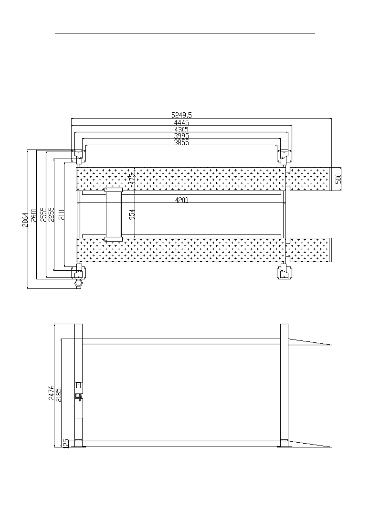
The device dimensions of machine
Check the FIG 1
The installation of equipment
The first step: site selection
Before installing the new lift, pay attention to the following matters:
(1) The location of the lift, according to the design and planning of the entire plan
requirements, as far as possible, place the dimension there is sufficient space.
(2) According Figure 1 foundation size , determine the installation location and carry out
the dash.
(3) Make sure the ground does not have any defects to ensure that the basis of concrete
strength of 3000psi (2.1kg/mm ²)
(4) Open the box to check whether the missing pieces and transport damage. Required by
the packing list.
Step 2: Connect the runway and the beam (Figure 2)
Step 3: Install the four column parts (Figure 2)
Step 4: Install the power unit and pipeline joints(Figure 5)
Step 5: Install a safety lock device (Figure 3) (Figure 8)
Step 6: The power supply according to the requirements on the motor nameplate, add
hydraulic oil.
Step 7: Jog up, observe the correct rope position (Figure 4) . Relieve the support under

6
the runway to runway decreased to the lowest point, adjusting the tension of the wire rope,
the four unanimously.
Step 8: Adjust the position between the column components and beams . Requirements
the slide board closest to column. Iron inserts to adjust the vertical column and the ground
plane. Drilling bolt hole and tighten the bolt.
Step 9: Adjust the levelness of the runway. Ascending to a height. Measure the level,
When need to adjust.Adjust nut(7)to the required position. Then lock.
Step 10: Install all plastic plate .
Step 11: Install running board and up ramp. (Figure 2)
Step 12: Stick all labels and finishing.

7
The debugging
☞Hydraulic station to fill the tank pressurized oil N32 or N46
☞To move the start button, so that the runway frame rise, removal of the support frame.
Special attention to the first jog observe whether rope in the embrace of a round tank,
location to be correct. (Figure 4)
☞Pull the handle valve A8 in the unlocking state to observe the safety hook 48 ability to
effectively disengage the insurance piece square hole 9 .
☞Down the runway rack to lowest position, adjust the nuts on the four wire rope, so that
tension is the same.
☞Adjust the level of the runway: press the start button, the runway frame up by the
appropriate location, drop the runway according to decline in valve on the hydraulic station.
Make the safety hook into the safety hole. Level detection level of the runway,to be
adjusted with reference to the installation Step 10.
☞No-load test up and down twice, check each part is working properly. Runway
lock reliability checks, and more repeated several times re-planted on the car to
check the hydraulic system is working properly.

8
Special attention
▲ Vehicles parked on the runway braking and tire wedge.
▲ Lifting and lowering vehicles, pay attention to people and things around to keep their
distance and not close to the lift.
▲ Maintenance man to enter the work area, check the runway should be properly locked
in the column lift.
▲ Four column installation should be vertical to the ground plane, otherwise be
dangerous to use!
▲Decline before the operation must be the first point of action to rise a little, so that the
lock block to leave the lift bar square hole in order to decline. Otherwise it will cause
damage to the control mechanism

9
Maintenance and inspection notes
Routine maintenance and inspection
1. Work location of an operation to check the safety lock
2. Check safety lock and unlock the lift bar and padlock
3. Check hydraulic fittings, hose leaks
4. Check the wire rope connections - is bent, broken, loose.
5. Check the wear of the wire rope lifting process.
6. Check all retainer connection must be reliable connection.
7. Check all bolts, nuts, screws connection - found loose shall immediately tighten
8. Check wires and switches for damage.
9. Check expansion bolts around the foundation strength.
10.After the lift is put into use, oil refers to the gun at least once a year or at regular
intervals on the cable axle lubrication
Weekly maintenance and inspection
1. Check the bolts strength and connections found loose, tighten immediately
2. Inspection inflation bolt around the foundation strength
3. Check the hydraulic oil liquid level
4. Check and tighten loose bolts, nuts, screws
5. Check all embrace round and embrace the axle with
6. Lubricate the cable wheel and cable axle
7. Check the wire rope wear, severe wear and tear be replaced immediately
8. Replace the hydraulic oil.
10
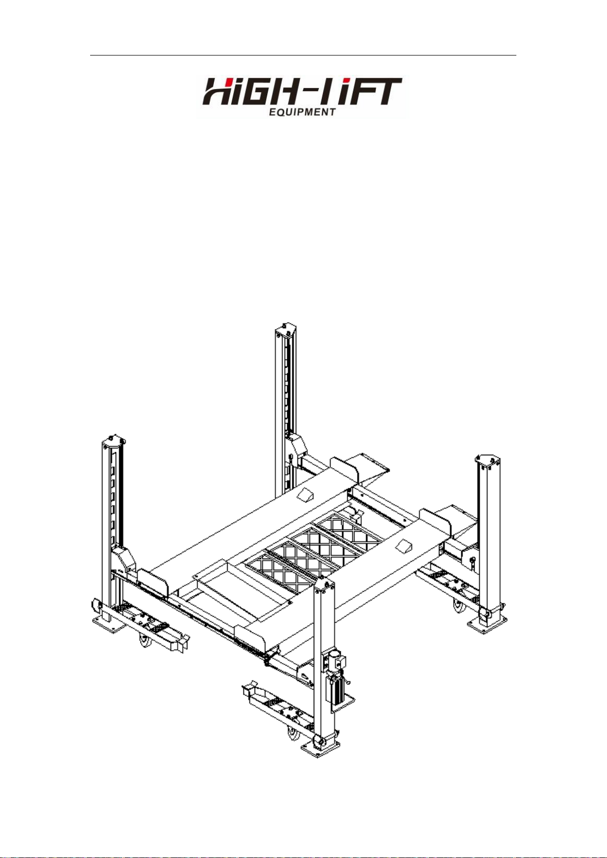
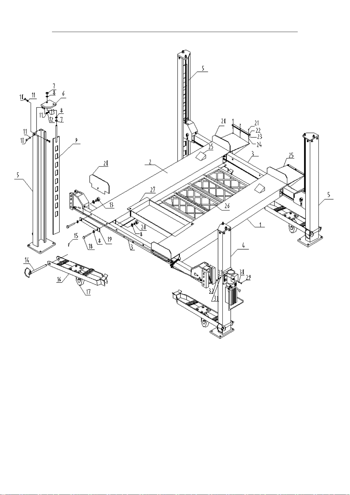
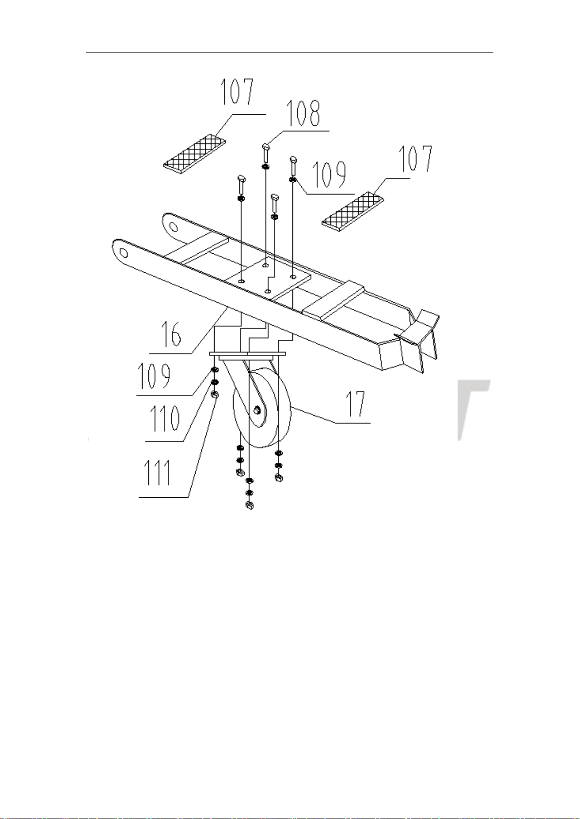
Parts of the device exploded view and schedule (In millimeters)
Figure 1
11
Figure 2

12
Figure 3

13
Figure 4

14
Figure 5

15
Figure 6
16
Figure 7
17
Figure 8
18
Lift part list
No.
Name
Qty
Remark
1
Main runway
1
2
Subsidiary runway
1
3
Beam
2
4
Main column
1
5
Subsidiary column
3
6
Column top cover assembly
Each 2
Bilateral symmetry
7
Nut M18
16
8
Flat gasket 18
24
9
Insurance piece
4
10
Hexagonal head bolt M12*30
16
11
Flat gasket 12
32
12
Spring washer
16
13
Nut M12
16
14
Axle of wheelset pin
4
15
R pin
4
16
Wheelset
4
17
Universal wheel
4
18
Hexagonal head bolt M18*100
8
19
Hook plate
4
20
Stop running plate
4
21
Cross head screw M5*16
6
22
slider
2
23
Gasket5
6
24
Nut 5
6
25
Up ramp
2
26
Oil pan
4
27
Tool pan
1
28
Spring washer 18
4
29
Hexagonal head bolt M8*20
4
30
Flat gasket 8
8
31
Spring washer 8
4
32
Nut 8
4
33
Protect cover
Each 2
Bilateral symmetry
34
Hexagonal head bolt M8*35
36
35
Spring washer 8
36
36
Flat gasket 8
36
37
Nylon slider
8
38
Hexagonal head bolt M8*16
4
39
Beam axle
4
19
40
Beam pulley
4
41
Flat gasket 4
12
42
Pulley stop collar
4
43
Set screw M8*15
4
44
Nipple
8
45
safety bar
4
46
Flat gasket 20
12
47
Self-lock nut M8
4
48
Manual safety hook
Each 2
Bilateral symmetry
49
Torsional spring spacer
4
50
Torsional spring
4
51
Stop falling safety hook
4
52
Insurance limit wheel
4
53
Insurance limit wheel pin
4
54
Cross head screw M6*15
4
55
Spring washer 6
4
56
Flat gasket 6
4
57
Safety bar limit nut
2
58
Nut M8
2
59
Nut M20
8
60
Flat gasket 20
8
61
Wire rope 1 L=11690mm
1
62
Wire rope 2 L=10250mm
1
63
Wire rope 3 L=6185mm
1
64
Wire rope 4 L=7610mm
1
65
Axle bumper 35
2
66
cylinder tailshaft
1
67
Oil cylinder
1
68
Sunk screw M8*20
1
69
nipple
1
70
multiplying wheel axle
1
71
Hexagonal head bolt M8*16
2
72
Spring washer 8
2
73
Flat gasket 8
2
74
Lock plate
1
75
Pulley
6
76
Power unit
1
77
copper backing
1
78
Double threaded joint
1
79
Oil tube L=2340mm
1
80
Nut (American systemm9/16)
1
81
Flat gasket 14
1
82
Small angle coupling
1
20
83
Oil tube L=660mm
1
84
explosion-proof valve
1
85
Big angle coupling
1
86
multiplying wheel
4
87
Pull plate supporting
1
88
Sunk screw M6*20
2
89
Oil cylinder plastic gasket
2
90
Flat gasket 6
2
91
Spring washer 6
2
92
Nut 6
2
93
Hexagonal head bolt M8*16
2
94
Spring washer 8
2
95
Flat gasket 8
2
96
silencer
1
97
Plastic plate
1
98
Hexagonal head bolt M8*16
4
99
Spring washer 8
4
100
Flat gasket 8
4
101
Wire rope 1
2
102
Flat gasket 24
12
103
Pulley
6
104
Stop collar 1
2
105
Wire rope axle 2
2
106
stop collar 2
2
107
rubber blanket
8
108
Hexagonal head bolt M10*30
16
109
Flat gasket 10
32
110
Spring washer 10
16
111
Nut M10
16
112
Black rubber ball
1
113
Safety bar 1
1
114
Limit sleeve
2
115
Nut 12
2
116
Safety connect sleeve
1
117
Safety bar 2
1
118
Hexagonal head bolt M8*30
4
119
Self-locking nut M8
8
120
Cardan joint
8
121
Nut M8
8
122
Short safety bar
2
123
Long safety bar
2
Other HiGH-LiFT Lifting System manuals


