HiGH-LiFT YL130 User manual

1
MODEL: YL130
PORTABLE MID-RISE LIFT
3,000Kg CAPACITY
Reference ANSI/ALI ALIOM safety
requirements for installation and service
of automotive lifts before installing lift.
PLEASE READ THE ENTIRE CONTENTS OF THIS MANUAL PRIOR TO INSTALLATION AND OPERATION. BY PROCEEDING WITH LIFT
INSTALLATION AND OPERATION YOU AGREE THAT YOU FULLY UNDERSTAND AND COMPREHEND THE FULL CONTENTS OF THIS
MANUAL. FORWARD THIS MANUAL TO ALL OPERATORS. FAILURE TO OPERATE THIS EQUIPMENT AS DIRECTED MAY CAUSE
INJURY OR DEATH.
HIGH-LIFT

2
IMPORTANT NOTICE
1. Read this manual thoroughly before installing, operating, or maintaining this lift.
2. This lift is designed for indoor use only and should not be installed in a pit or depression.
3. The floor on which the lift is to be installed must be 4"(101mm) minimum thickness concrete, with a minimum
compressive strength of 3000 psi (20 MPa) and reinforced with steel bar.
4. The lifts have specific electrical requirements as described in the Installation Instructions section of this manual.
5. This lift has a minimum ceiling height requirement as described in the Installation Instructions section of this manual.
6. Failure by the owner to provide the recommended shelter, mounting surface, electrical supply, and ceiling height could
result in unsatisfactory lift performance, property damage, or personal injury.
7. Do not attempt to install this lift if you have never been trained on basic automotive lift installation procedures.
Reference ANSI/ALI ALIOM requirements for installation and service of automotive lifts.
8. Never attempt to lift components without proper lifting tools such as forklift or cranes. Stay clear of any moving parts
that can fall and cause injury. These instructions must be followed to insure proper installation and operation of your lift.
9. High Lift Equipment will assume no liability for loss or damage of any kind, expressed or implied resulting from improper
installation or use of this product.
10. This lift is rated to 6,000-lbs lifting capacity. NEVER EXCEED rated lifting capacity of lift.
11. Qualified person must be consulted for seismic loads and other local or state requirements.
DEFINITIONS OF HAZARD LEVELS
Identify the hazard levels used in this manual with the following definitions and signal words.
Hazards or unsafe practices which could result in severe personal injury or death.
Hazards or unsafe practices which may result in minor personal injury, product or property damage.
Lubricate all plastic guide blocks, bearings, and shafts with grease prior to operating the lift. Lubricate all on a weekly basis.
Motors and all electrical components are not sealed against the weather and moisture. Install this lift in a protected indoor
location. Failure by the owner to provide the recommended shelter could result in unsatisfactory lift performance, property
damage, personal injury, and may void the warranty.
BE SAFE: YOUR NEW LIFT WAS DESIGNED AND BUILT WITH SAFETY IN MIND. HOWEVER, YOUR OVERALL
SAFETY CAN BE INCREASED WITH PROPER TRAINING AND THOUGHTFUL OPERATION ON THE PART OF THE
OPERATOR. DO NOT OPERATE OR REPAIR THIS EQUIPMENT WITHOUT READING THIS MANUAL AND THE
IMPORTANT SAFETY INSTRUCTIONS SHOWN INSIDE. KEEP THIS OPERATION MANUAL NEAR THE LIFT AT ALL
TIMES. MAKE SURE THAT ALL USERS READ AND UNDERSTAND THIS MANUAL.
IMPORTANT SAFETY INSTRUCTIONS
HIGH-LIFT

3
READ THESE SAFETY INSTRUCTIONS ENTIRELY
Do not attempt to install this lift if you have never been trained on basic automotive lift installation procedures. Never
attempt to lift components without proper lifting tools such as a forklift or crane. Stay clear of any moving parts that can fall
and cause injury.
1. READ ALL INSTRUCTIONS.
2. READ AND UNDERSTAND all safety warning procedures before operating lift.
3. KEEP AREA WELL LIGHTED.
4. WARNING! RISK OF EXPLOSION. This equipment has internal arcing or sparking parts which should not be exposed
to flammable vapours. This machine should not be located in a recessed area or below floor level.
5. KEEP CONTROL HANDLES AND / OR BUTTONS dry, clean and free from grease and oil.
6. CARE MUST BE TAKEN as burns can occur from touching hot parts on the hydraulic unit’s electric motor.
7. DO NOT operate equipment with a damaged power cord or if the equipment has been dropped or damaged until it has
been examined by a qualified service person.
8. DO NOT let the power cord come in contact with hot manifolds or moving fan blades.
9. IF AN EXTENSION CORD IS NECESSARY, a cord with a current rating equal to or more than that of the equipment
should be used. Cords rated for less current than the equipment may overheat. Care should be taken to arrange the
cord so that it will not be tripped over or pulled.
10. ALWAYS UNPLUG EQUIPMENT FROM ELECTRICAL OUTLET WHEN NOT IN USE. Never use the power cord to
pull the power plug from the outlet. Grasp the plug and pull to disconnect.
11. LET EQUIPMENT COOL COMPLETELY BEFORE PUTTING AWAY. Loop power cord loosely around equipment
when storing.
12. TO REDUCE THE RISK OF FIRE, do not operate equipment in the vicinity of open containers of flammable liquids
(i.e., gasoline).
13. ADEQUATE VENTILATION SHOULD BE PROVIDED when working on operating internal combustion engines.
14. KEEP HAIR, LOOSE CLOTHING, FINGERS, AND ALL PARTS OF THE BODY AWAY FROM MOVING PARTS.
15. TO REDUCE THE RISK OF ELECTRIC SHOCK, do not use on wet surfaces or expose to rain.
16. USE ONLY AS DESCRIBED IN THIS MANUAL. Use only manufacturer’s recommended attachments.
17. DO NOT raise vehicle on the lift until installation is completed as instructed in this manual.
18. KEEP HANDS AND FEET CLEAR. Remove hands and feet from any moving parts. Keep feet clear of lift when
lowering. Avoid pinch points.
19. KEEP WORK AREA CLEAN. Cluttered work areas invite injuries.
20. CONSIDER WORK AREA ENVIRONMENT. Do not expose equipment to rain. DO NOT use in damp or wet locations.
Keep area well lighted.
21. ONLY TRAINED OPERATORS should operate this lift. All non-trained personnel should be kept away from work
area. Never let non trained personnel come in contact with or operate lift.
HIGH-LIFT

4
22. USE LIFT CORRECTLY. Use lift in the proper manner. Never use lifting adapters other than what is approved by the
manufacturer.
23. DO NOT override self-closing lift controls.
24. REMAIN CLEAR of lift when raising or lowering vehicle.
25. CLEAR AREA if vehicle is in danger of falling.
26. ALWAYS ENSURE that the safety locks are engaged before any attempt is made to work on or near vehicle.
27. DRESS PROPERLY. Non-skid steel toe footwear is recommended when operating lift.
28. GUARD AGAINST ELECTRIC SHOCK. This lift must be grounded while in use to protect the operator from electric
shock. Never connect the green power cord wire to a live terminal. This is for ground only.
29. DANGER! The power unit used on this lift contains high voltage. Disconnect power at the receptacle before
performing any electrical repairs. Secure plug so that it cannot be accidentally plugged-in during service.
30. ALWAYS WEAR SAFETY GLASSES. Everyday eyeglasses only have impact resistant lenses. They are not safety
glasses.
31. MAINTAIN WITH CARE. Keep lift clean for better and safe performance. Follow manual for proper lubrication and
maintenance instructions. Keep control handles and / or buttons dry, clean and free from grease and oil.
32. STAY ALERT. Watch what you are doing. Use common sense. Be aware!
33. CHECK FOR DAMAGED PARTS. Check for alignment of moving parts, breakage of parts or any condition that may
affect its operation. Do not use lift if any component is broken or damaged.
34. NEVER remove safety related components from the lift. Do not use lift if safety related components are damaged or
missing.
NOTE: If attachments, accessories, or configuration modifying components that are located in the load path, affect
operation of the lift, affect the lift electrical listing or affect intended vehicle accommodation are used on this lift
and, if they are not certified for use on this lift, then the certification of this lift shall become null and void. Contact
High Lift Equipment for information pertaining to certified attachments, accessories, or configuration modifying
components.
When removing the lift from the shipping angles pay close attention as the posts can slide and can cause injury. Prior to
removing the bolts make sure the posts are held securely by a forklift or some other heavy lifting device.
SHIPPING DAMAGE CLAIMS: WHEN THIS EQUIPMENT IS SHIPPED, TITLE PASSES TO THE PURCHASER UPON RECEIPT FROM THE CARRIER.
CONSEQUENTLY, CLAIMS FOR THE MATERIAL DAMAGED IN SHIPMENT MUST BE MADE BY THE PURCHASER AGAINST THE TRANSPORTATION
COMPANY AT THE TIME SHIPMENT IS RECEIVED.
SAVE THESE INSTRUCTIONS
OWNER / EMPLOYER RESPONSIBILITIES
•Shall ensure that lift operators are qualified and that they are trained in the safe use and operation of the lift using the
manufacturer’s operating instructions and regional requirements.
HIGH-LIFT

5
•Shall establish procedures to periodically inspect the lift in accordance with the lift manufacturer’s instructions and
regional requirements. The Employer Shall ensure that lift inspectors are qualified and that they are adequately trained
in the inspection of the lift.
•Shall establish procedures to periodically maintain the lift in accordance with the lift manufacturer’s instructions and
regional requirements, Inspection and Maintenance and The Employer Shall ensure that lift maintenance personnel are
qualified and that they are adequately trained in the maintenance of the lift.
•Shall maintain the periodic inspection and maintenance records recommended by the manufacturer and regional
requirements.
•Shall display the lift manufacturer’s operating instructions; ALI/SM 93-1, ALI Lifting it Right safety manual; ALI/ST-10
ALI Safety Tips card; in a conspicuous location in the lift area convenient to the operator.
•Shall not modify the lift in any manner without the prior written consent of the manufacturer or regional requirements.
•Shall provide necessary lockout/ tagout means for energy sources per ANSI Z244.1-1982 (R1993), safety requirements
for the lockout / tagout of energy sources, before beginning any lift repairs.
INSTALLER / OPERATOR: PLEASE READ THE ENTIRE CONTENTS OF THIS MANUAL PRIOR TO INSTALLATION
AND OPERATION. BY PROCEEDING WITH LIFT INSTALLATION AND OPERATION YOU AGREE THAT YOU FULLY
UNDERSTAND AND COMPREHEND THE FULL CONTENTS OF THIS MANUAL. FORWARD THIS MANUAL TO ALL
OPERATORS. FAILURE TO OPERATE THIS EQUIPMENT AS DIRECTED MAY CAUSE INJURY OR DEATH.
•I have visually inspected the site where the lift is to be installed and verified the concrete to be in good condition and
free of cracks or other defects. I understand that installing a lift on cracked or defective concrete could cause lift failure
resulting in personal injury or death.
•I understand that a level floor is required for proper installation and level lifting.
•I understand that I am responsible if my floor is of questionable slope and that I will be responsible for all charges
related to pouring a new level concrete slab if required and any charges.
•I understand that High Lift lifts are supplied with concrete fasteners meeting the criteria of the Australian Standards, and
that I will be responsible for all charges related to any special regional structural and/or seismic anchoring requirements
specified by any other agencies and / or codes such as the Uniform Building Code (UBC) and / or International Building
Code (IBC).
•I will assume full responsibility for the concrete floor and condition thereof, now or later, where the above equipment
model(s) are to be installed. Failure to follow danger, warning, and caution instructions may lead to serious personal
injury or death to operator or bystander or damage to property.
•I understand that High Lift lifts are designed to be installed in indoor locations only. Failure to follow installation
instructions may lead to serious personal injury or death to operator or bystander or damage to property or lift.
Failure to follow danger, warning, and caution instructions may lead to serious personal injury or death to operator or
bystander or damage to property.
HIGH-LIFT

6
Please read entire manual prior to installation. Do not operate this machine until you read and understand all the dangers,
warnings and cautions in this manual. For additional copies or further information, contact:
HighLift™
42 Gregory Street West
Lake Gardens Victoria 3355
INSTALLER / OPERATOR PROTECTIVE EQUIPMENT
Personal protective equipment helps makes installation and operation safer, however, it does not take the place of safe
operating practices. Always wear durable work clothing during any installation and/or service activity. Shop aprons or shop
coats may also be worn, however loose-fitting clothing should be avoided. Tight fitting leather gloves are recommended to
protect technician hands when handling parts. Sturdy leather work shoes with steel toes and oil resistant soles should be
used by all service personnel to help prevent injury during typical installation and operation activities.
Eye protection is essential during installation and operation activities. Safety glasses with side shields, goggles, or face
shields are acceptable. Back belts provide support during lifting activities and are also helpful in providing worker
protection. Consideration should also be given to the use of hearing protection if service activity is performed in an
enclosed area or if noise levels are high.
M6K PRODUCTION
ITEM No.
PART NUMBER
DESCRIPTION
QTY
1
5215935
POST ASSEMBLY
2
2
5215936
POWER UNIT STAND ASSEMBLY
1
3
5250293
PARTS BOX
1
4
5215938
ARM ASSEMBLY
4
5
5906033
BRANDING LABEL
4
6
5906034
SAFETY LABEL
1
7
5906035
SAFETY LOCKS WARNING LABEL
2
8
5906005
MAX CAPACITY NTRL 6K LABEL, ENLISH-FRENCH
1
9
5906036
SERIAL TAG
1
10
5905377
NOTICE LABEL
1
11
5905109
WARNING
1
HIGH-LIFT

7
12
5905654
POWER UNIT STAND ASSEMBLY
ITEM No.
PART NUMBER
DESCRIPTION
QTY
1
5601535
BOTTOM PLATE WELDMENT, STAND
1
2
5601474
M6K HOSE STORAGE BOX WELDMENT
1
3
5755171
MAXJAX STAND HANDLE
2
4
5737162
STAND SUPPORT PLATE
1
5
5215970
HAND CART WHEEL ASSEMBLY
2
6
5715041
Ø25 VINYL GRIP
2
7
5716056
VINYL CAP, Ø22 I.D
2
8
5540113
E RING Ø1/2” OD TRAURC 5133-50
2
9
5545141
WASHER M12 X 24 FLAT CL 10.9
4
10
5530378
PHPS M6 X 1.0. X 40 MM
12
11
5535357
NUT M6 X 1.0 NL
12
PARTS BAG
ITEM No.
PART NUMBER
DESCRIPTION
QTY
1
5505071
M6K SAFETY PIN ASSEMBLY
4
2
5746491
LIFT HEAD RELEASE PIN
4
3
5505001
SAFETY CLEVIS PIN
2
4
5530738
HHB M10 X 1.5 X 25
4
HIGH-LIFT

8
5
5545200
WASHER M10 X Ø18 SL
4
6
5530377
HHB M8 X 1.25 X 55
4
7
5550077
FTG -06 NPTF X -06 NPTF, HEX NIPPLE
2
8
5550076
FTG 45° ELB -06 NPTF X -06 NPTF
2
9
5535001
NUT M8 X 1.25 ML
12
10
5550014
FTG NPL -06 NPT F X 3/8 QUICK CONNECTOR COUPLER MALE; NON SPILL
DESIGN
2
11
5550209
FTG -04 NPTF X -06 NPTF, STRAIGHT EXPANDER
2
12
5505350
MODEL #211 HAIR PIN/LARGE
2
13
5540075
R.H. 2.5 WIRE DIA. , Ø20.5 X 75 LG
4
14
5545535
C WASHER SHIM FOR LIFTS
21
15
5530261
PHPS M6 X 1 X 10
4
16
5530304
HHB M8 X 1.25 X 20
8
17
5550074
FTG 90° ELB 3/8” JIC MALE X 3/8” ORB MALE, LONG
1
18
5550170
FTG 90° ELB 3/8” JIC MALE X 3/8” NPTF MALE, LONG
1
PARTS BOX
ITEM No.
PART NUMBER
DESCRIPTION
QTY
1
5174046
PARTS BAG
1
2
5715003
POWER UNIT VIBRATION DAMPENER
1
3
5601488
M6K LIFT HEAD PIN WELDMENT
4
4
5575061
M6K POST WHEEL
4
5
5601487
M6K POST STRAP ASSEMBLY
2
6
5736604
TWO POST LIGHT DUTY BOLT ON ARM RESTRAINT GEAR
4
7
5210236
SAFETY WELDMENT
2
8
5716057
SAFETY COVER
2
9
5570241
HYDRAULIC HOSE ASS. Ø10 X 4520 MM
2
10
5570242
HYDRAULIC HOSE ASS Ø10 X 317 MM DS
1
11
5590103
HYDRAULIC FLOW DIVIDER; MTE
1
12
5746390
MEDIUM LIFT PAD EXTENSION Ø35 X 113 MM
4
13
5215507
ROUND LIFT PAD ADAPTER ASSEMBLY
4
14
5530376
7/8” x 3-13/16” DROP IN SLEEVE ANCHOR
10
15
5580012
LIQUID PTFE THREAD SEALANT 50 ML
1
16
5530405
HHB 5/8” X 40”
1
17
5535100
NUT 5/8” - 11 HN
1
PARTS BAG
HIGH-LIFT

9
MAXJAX PARTS BOX
HIGH-LIFT

10
INSTALLATION INSTRUCTIONS
TOOLS REQUIRED
•Rotary Hammer Drill or Similar
•7/8"(22mm) Masonry Bit
•Hammer
•4 Foot Level (1.5 M)
•Open End Wrench Set: Metric
•Socket and Ratchet Set: Metric
•Hex Key / Metric Allen Wrench Set
•Large Crescent Wrench
•Large Phillips Screwdriver
•Chalk Line
•Medium Phillips Screwdriver
•Tape Measure: 25 Foot (7.5 M)
Minimum
IMPORTANT NOTICE
These instructions must be followed to ensure proper installation and operation of your lift. Failure to comply with these
instructions can result in serious bodily harm and void product warranty. Manufacturer will assume no liability for loss or
damage of any kind, expressed or implied resulting from improper installation or use of this product.
STEP 1
SELECTING SITE
BEFORE INSTALLING YOUR NEW LIFT, CHECK THE FOLLOWING:
1. LIFT LOCATION: Always use architects plans when available. Check layout dimension against floor plan
requirements making sure that adequate space is available.
2. OVERHEAD OBSTRUCTIONS: The area where the lift will be located should be free of overhead obstructions such
as heaters, building supports, electrical lines etc.
3. DEFECTIVE FLOOR: Visually inspect the site where the lift is to be installed and check for cracked or defective
concrete.
4. OPERATING TEMPERATURE. Operate lift only between temperatures of 41° - 104° F (5º - 40 º C).
5. Lift is designed for INDOOR INSTALLATION ONLY.
STEP 2
FLOOR REQUIREMENTS
This lift must be installed on a solid level concrete floor minimum 4"(101mm) thick, compressive strength 3000 psi
(20 MPa) with no more than 3 degrees of slope. FAILURE TO DO SO COULD CAUSE PERSONAL INJURY OR
DEATH.
DO NOT install this lift on any asphalt surface or any surface other than concrete.
DO NOT install this lift on expansion seams or on cracked or defective concrete.
DO NOT install this lift on a second / elevated floor without first consulting building architect.
DO NOT install this lift outdoors.
STEP 3
INSTALLING HYDRAULIC CYLINDERS
1. Install the column wheels (P/N 5575061) using M8x55 hex head bolts (P/N 5530377) and M8 nylon lock nut
HIGH-LIFT

11
(P/N 5535001) onto each column. Turn the columns over and lay them down with the open side up. Slide the lift head
to the top of the post. Remove the cylinder from the post. (See figure 1)
2. Remove the 6mm allen bolt and install the
Cylinder Fittings. Assemble all fittings
together, including quick disconnect,
preferably in a vice. Install fitting assembly
into cylinder.
(See figure 2)
3. Slide the fitting assembly through the
access hole located on the backside of the
columns. (See figure 3)
4. Slide the cylinders through the lift head tube. (See figure 4)
5. Slide the Lift Head until it rests firmly on the Baseplate. Stand the column up.
6. Install the Column Handles (P/N 5505071) with M10 x 25 Hex Head Bolts (P/N 5530738) with M10 Washers
(P/N 5545200) and Post Straps Assemblies (P/N 5601487 ) with M10 x 40mm hex bolts and M10 nylon lock nuts.
(See figure 5)
Fig. 4
Fig. 2
P/N 5505071
4
P/N 5530738
4
P/N 5535013
4
P/N 5530302
4
P/N 5550209
1
P/N 5550076
1
P/N 5550077
1
P/N 5550014
1
Fig. 5
Fig. 3
Fitting Assembly
Fig. 1
Cylinder
Lift Head
HIGH-LIFT

12
1
(
2
NOTE:
3
)
)
4
.
)
5
)
HIGH-LIFT

13
STEP 5
SITE LAYOUT
1. Determine the location of where the lift will be installed based on the size of vehicles servicing. The dimensions shown
below are rough guidelines. "Dry-fit" the vehicles intended to be serviced in the bay by referring to the ALI Lifting Point
Guide for appropriate lift points before finalizing the column spacing.
2. Once a location is determined, use a carpenter’s chalk line to layout a grid for the post locations. Keep all dimensions and
squareness within 1/8"or malfunctioning of the lift can occur.
3. After the post locations are properly marked, use a chalk or crayon to make an outline of the columns on the floor at each
location using the post base plates as a template.
4. Double check all dimensions and make sure that the layout is perfectly square.
NOTE:
Wide or narrow installation is possible. The lift can be installed at a width that suits the vehicles you will be raising.
You may even choose to install additional anchors at varied column positions for adaptability to multiple vehicle
configurations.
5. Recommended bay dimensions 20'deep and 14'wide.
6. Clearance around lift should be 5”. Clearance above lift must exceed height of top of raised vehicle.
Full size trucks
120"(3048mm) - 135"(3429mm) Typical
Use the edge of the base plate to line up the posts along the chalk line.
Sport compacts
105
(2667mm) - 115
(2921mm)
Typical
Mid-size
110
(2794mm) - 120
(3048mm) Typical
Light duty / sport trucks
115
(2921mm) - 120
(3048mm) Typical
HIGH-LIFT

14
STEP 6
INSTALLATION OF POWER DROP ANCHORS
1. Before proceeding, double check location and measurements, make
certain that the base plates of each column are aligned with the chalk
lines. The concrete must be minimum of 4"(101mm) thick with a
minimum compressive strength of 3000 psi (20 MPa). FOLLOW
PROCEDURE EXACTLY FOR PROPER FITTING AND ALIGNMENT OF
ANCHORS. (See figure 10)
2. Use the Base Plate as a guide. Using a rotary hammer drill with a 7/8"
concrete bit, drill the concrete for each anchor to a minimum depth of
5".
(See figure 11)
Do not ream the hole or allow the drill to wobble. Use caution to not move
the Columns when removing the Posts. We recommend having someone
secure or stand on the columns. Repeat for all holes on both columns and move the columns out of the way. After
drilling, thoroughly clean hole using a vacuum cleaner or compressed air and a nylon brush.
3. Set the Anchor Embedment Depth: Fully thread the 5/8"
Setting Tool (P/N 5530405) with assembled Nut and Washer into the anchor. Set the distance between the top of the
anchor and the bottom of the Nut and Washer to 5/8". (See figure 12)
4. After setting the Nut and Spacer, place the Anchor into the hole and
hammer downward on the Setting Tool until the nut and washer are flush
with the surface of the concrete. (See figure 13)
5. To set the Anchor, tighten the Nut while holding the Bolt head (to assure
the anchor does not spin in place). Do not use an impact wrench for this
step. Tighten to reach an installation torque of 90 ft-lbs. (See figure 14)
6. Once the anchor is set remove the Setting Tool and clear the anchor with
compressed air to remove any concrete dust
Fig. 11
Drill hole
a minimum o
5
127mm) deep
.
Chalk Line
D
B
A
C
E
Fig. 10
HIGH-LIFT

15
7. Install both columns with bolts and washers to anchors, check plumb and measurements as shown below.
8. If shimming is required, insert the shims as necessary under the
base plate so that when the provided 5/8 x 2"Anchor Bolts are
tightened, the columns will be plumb both side to side and front to
rear. (See figure 15)
9. With the shims and anchor bolts in place, tighten all 5/8 x 2"Anchor
Bolts tight to the base plate. DO NOT USE AN IMPACT WRENCH or
the anchors could become compromised.
NOTE:
It will be helpful to mark on or otherwise note the location of shims
used at each drop anchor to assist at time of re-installation.
Inspect all drop-in anchors for proper setting and or damage each time the lift is re-installed. Inspect the concrete for
cracks defects and/or damage. Do not re-install the lift if any of the drop-in anchors are defective or the concrete is
cracked or defective.
It may be necessary to shim the columns to ensure that the columns are plumb. The columns must be plumb and
square, or damage or injury may occur when using the lift. Do not exceed 1/8" total shim thickness.
IMPORTANT LEVELING INSTRUCTIONS
Before operating your lift, check to make sure both “A” and “B” measurements are equal. The lift arms must be level
before operation. If your lift arms are not level, shim the columns as required.
NOTE
:
Always wear
safety glasses. Follow
drill manufacturer’s inst
-
ructions. Use only solid
carbide-tipped drill bits
meeting ANSI B212.15
diameter standards.
Fig. 12
Fig. 13
Fig. 14
from the threads.
Fig. 15
HIGH-LIFT

16
STEP 7
CONNECTING HYDRAULIC LINES
1. Thread one end of the 3/8 NPT hose fittings into one of the top ports of the Flow Divider. Do this with both hoses.
each hose. (See figure 17)
Recheck all fitting connections to make sure they are properly tightened
before proceeding.
Position the power unit stand at the front or rear of the vehicle.
Connect the Female Quick Disconnect fitting to the Male Quick
Disconnect located at the bottom of each column. (See figure 18)
Female Quick
Disconnect
Fitting
Install the Female Quick Disconnect fittings to the opposite end of
Fig. 16
3
/8 NPTF Hose
Fittings
Fig. 18
(
See figure
16)
Fig. 17
HIGH-LIFT

17
STEP 8
HYDRAULIC POWER UNIT SET UP
1. Fill the power unit reservoir with 7 quarts (6.6 L) of AW-32 hydraulic oil or Dexron III or VI automatic transmission
fluid. Make sure the funnel used to fill the power unit is clean. After bleeding the cylinders, check the oil level to see if
additional oil is needed to ensure the reservoir is full.
2. The lift should be plugged into a dedicated circuit with a 20-amp circuit breaker. The standard power unit for this lift is:
US: 110V, 60Hz, single phase
CE: 230V, 50Hz, single phase
ALL WIRING MUST BE PERFORMED BY A CERTIFIED ELECTRICIAN ONLY.
RISK OF EXPLOSION
This equipment has internal arcing or parts that may spark and should not be exposed to flammable vapours. The motor
should not be located in a recessed area or below floor level.
•DO NOT run power unit without oil. Damage to pump can occur.
•The power unit must be kept dry. Damage to power unit caused by water or other liquids such as detergents, acid etc.,
is not covered under warranty.
•Improper electrical hook-up can damage the motor and will not be covered under warranty.
•Motor cannot run on 50hz without a physical change in the motor. (US - only)
•Use a separate breaker for each power unit.
•Protect each circuit with a time delay fuse or circuit breaker. (US-only)
STEP 9
INSTALLING THE LIFT ARMS
1. Place the lift arm assembly on the lift heads. Install the lift head pins into the lift head and through
the holes in the arm assembly. Install the quick release pin into place on the arm pin. (See figure 20 and 21)
2. Raise the lift high enough so that the arm gear stops. Attempt to automatically engage the restraint gears on the
arms.
3. Loosen the Arm Restraint Gear Ring Bolts and adjust the Arm Restraint Gears so that the teeth on the gear ring
mesh smoothly with the teeth on the gears of the arm gear stop. (See figure 22)
Fig. 20
Quick Release Pin
Fig. 21
HIGH-LIFT

18
4. Tighten the Gear Ring Bolts.
5. Verify the operation of the arm gear stops by pulling up on the
key ring of the arm gear stops. Pivot the arms back and forth
and test the operation of the arm gear stops in various
positions. When releasing the arm gear stop, the pin
should drop, and the gears should engage. (See figure
23)
6. Ensure that the arms do not move when a force of at least
100 pounds is applied laterally to the fully extended
arms. If they move, readjust the arm restraint gear ring
and/or tighten the arm restraint gear ring bolts.
7. Adjust the gear ring on the arm as necessary to ensure
smooth operation and solid engagement of all four arm
restraint pins.
Each arm restraint assembly must be inspected and adjusted as
needed before each and every time the lift is operated. Do not
operate the lift if any of the four arm restraint systems are not
functioning properly. Replace any broken components or components with broken teeth only with authorized or
approved replacement parts.
STEP 10
INSTALLING THE SAFETY RELEASE LATCH
SEE PAGE 30
STEP 11
BLEEDING THE CYLINDERS
1. With the lift in an elevated position, the hoses connected and the oil reservoir full, loosen the bleeder screws
located at the top of each hydraulic cylinder using an allen wrench. Do not completely remove the bleeder screws.
Watch and listen for trapped air escape the cylinders and fluid begins to
weep from the screw area. Once steady fluid appears, re-tighten the
bleeder screw and clean-up excess oil. (See
figure 19)
The lift will move down when bleeding, make sure all equipment, personnel,
hands and feet are clear before starting bleeding procedure.
2. Repeat Bleeding procedure on opposite cylinder.
3. Press the lowering handle on the power unit until the lift lowers
completely to the floor.
Fig. 22
Arm Restraint Gear
Fig. 23
Bleed Screw
Fig. 19
HIGH-LIFT

19
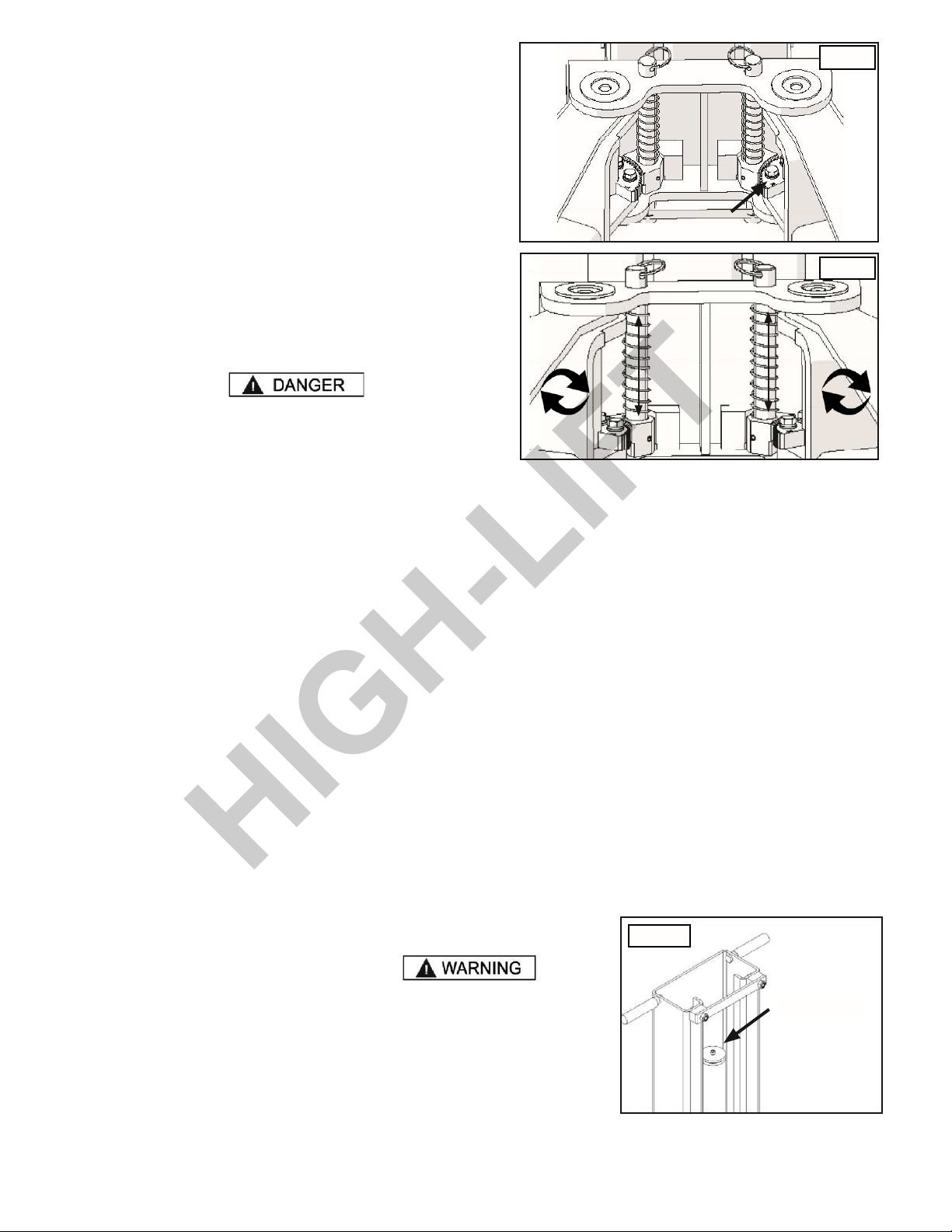
DO NOT use lift if an unlevel lifting condition occurs at the arm pad locations that is greater than 3.5"(89mm). If an
unbalanced condition occurs, follow the bleeding instructions shown on this page or consult Technical Support. The lift
must be re-leveled, shimmed and bled each time the lift is reinstalled. Failure to follow these instructions can result in
serious injury or death.
STEP 12
LIFT START UP / FINAL ADJUSTMENTS
DURING THE START-UP PROCEDURE, OBSERVE ALL OPERATING COMPONENTS AND CHECK FOR PROPER
INSTALLATION AND ADJUSTMENT. DO NOT ATTEMPT TO RAISE VEHICLE UNTIL A THOROUGH OPERATIONAL
CHECK HAS BEEN COMPLETED.
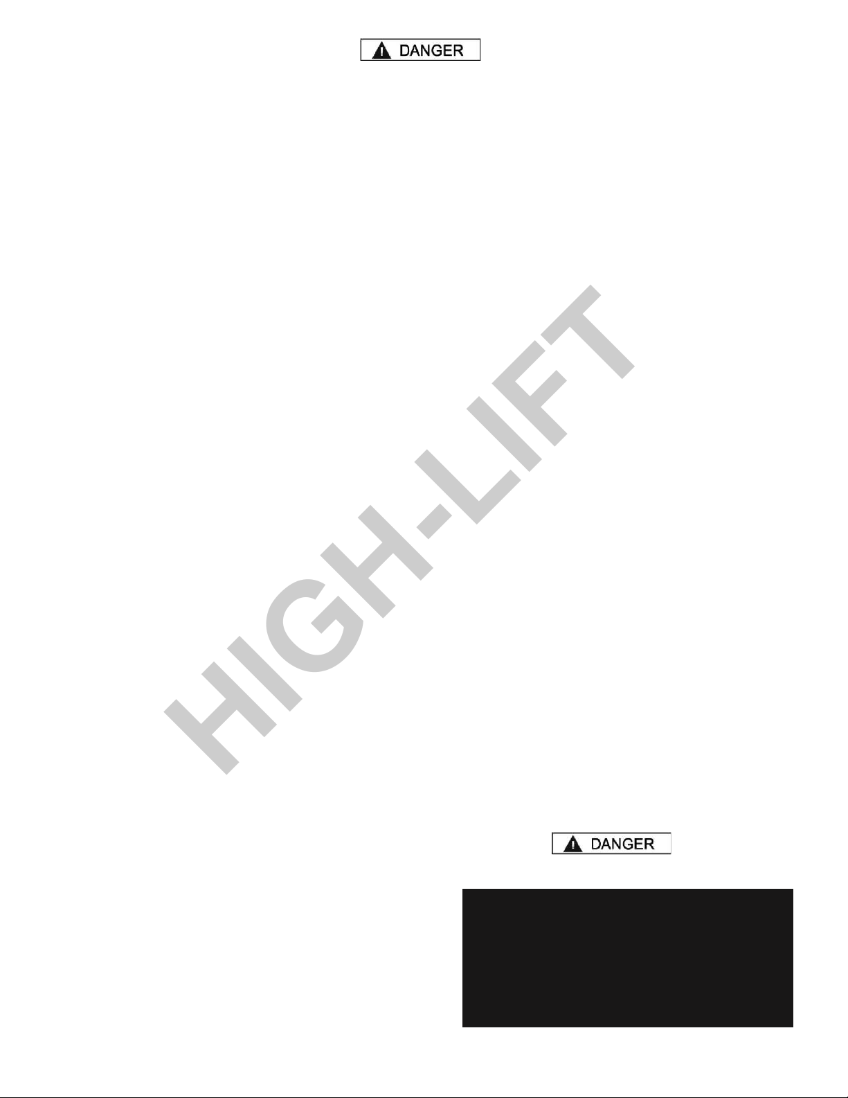
1. Apply white lithium grease or equivalent to the inside of the columns where the slide blocks glide.
2. Test the power unit by pressing the push-button switch. Raise the lift a few inches and check all those connections for
leaks. If the motor gets hot or sounds peculiar, stop and check all electrical connections.
3. Raise the lift to it’s maximum height off the floor until the lift head stops.
4. Lower the lift down below the first safety stop.
POST INSTALLATION CHECK OFF
‡Columns are properly levelled
‡Anchor bolts are tightened
‡Electric power supply confirmed
‡Check for hydraulic leaks
‡Check oil level
‡Lubrication of critical components
‡Check for overhead obstructions
‡Lift arms are level
‡Arm restraints properly adjusted
‡All screws, bolts, and pins are secured
‡Surrounding area is clear
‡Operation, maintenance and safety manuals on site
LIFT OPERATION SAFETY
•NEVER exceed rated capacity of 6,000-lbs.
•Tighten all anchor bolts prior to operation. If anchor
bolts are loose, or any component of the lift is
defective, do not use lift.
•DO NOT remove or disable arm restraints.
•DO NOT block, open or override self-closing lift
controls; they are designed to return to the “Off” or
Neutral position when released.
•ALWAYS inspect all quick connect/disconnect hose
ends before any attempt is made to raise vehicle.
•ALWAYS be sure to have proper overhead
clearance.
•ALWAYS load vehicle on lift carefully. Position the
contact pads according to the vehicle manufacturer’s
recommended lift points. Raise lift until lift pads
contact vehicle. Check pads for secure contact with
the vehicle.
NOTE:
Refer to ALI Quick Reference Guide for all point
recommendations, dangers and safety data.
•ALWAYS remain clear of lift when raising or
lowering vehicles.
•Do NOT use lift if an unlevel lifting condition occurs
that is greater 3.5"(89 mm).
•DO NOT rock the vehicle or remove heavy
components while on the lift that may alter weight
distribution
•ALWAYS ensure Safety Locks are engaged before
any attempt is made to work on or near vehicle.
•NEVER go under raised vehicle if Safety Locks are
not engaged.
VISUALLY CONFIRM THAT ALL SAFETY LOCKS
ARE ENGAGED BEFORE ENTERING WORK
AREA. SUSPENSION COMPONENTS USED ON
THIS LIFT ARE INTENDED TO RAISE AND
LOWER LIFT ONLY AND ARE NOT MEANT TO BE
LOAD HOLDING DEVICES. REMAIN CLEAR OF
ELEVATED LIFT UNLESS VISUAL
CONFIRMATION IS MADE THAT SAFETY LOCKS
HIGH-LIFT

20
ARE FULLY ENGAGED AND THE LIFT IS
LOWERED ONTO THE SAFETY LOCKS, REFER
TO OPERATION MANUAL FOR PROPER SAFETY
LOCK
PROCEDURES AND/OR FURTHER INSTRUTIONS.
WHEN LOWERING THE LIFT PAY CAREFUL
ATTENTION THAT ALL PERSONNEL AND
OBJECTS ARE KEPT CLEAR. ALWAYS KEEP A
VISUAL LINE OF SITE ON THE LIFT AT ALL
TIMES. ALWAYS
MAKE SURE THAT ALL LOCKS ARE
DISENGAGED.
IF ONE OF THE LOCKS INADVERTENTLY LOCKS
UPON DESCENT THE VEHICLE MAY DISMOUNT
CAUSING PERSONAL INJURY OR DEATH.
•ALWAYS remove tool trays, stands, etc. before
lowering lift.
•ALWAYS release safety locks before attempting
to lower lift.
•ALWAYS move the lift arms to provide an
unobstructed exit before removing vehicle from lift
area.
•NEVER drive over the lift arms.
STEP 13
LIFT OPERATION
BE SURE TO READ ALL SAFETY TIPS PRIOR TO OPERATING LIFT. FAILURE TO DO SO MAY RESULT IN
SERIOUS INJURY OR DEATH.
TO RAISE VEHICLE:
HIGH-LIFT
Table of contents
Other HiGH-LiFT Lifting System manuals
Popular Lifting System manuals by other brands

King Industrial
King Industrial EXCELSIOR XL-125 instruction manual

Custom Equipment
Custom Equipment Hy-Brid Lifts HB 1030CE MAINTENANCE & TROUBLESHOOTING MANUAL

Arjo
Arjo Maxi Sky 440 Instructions for use

Southworth
Southworth PUN Installation, operation & maintenance manual

Challenger Lifts
Challenger Lifts EnviroLift EV1020QC Installation, operation & maintenance manual

AJ
AJ 31021 operating instructions