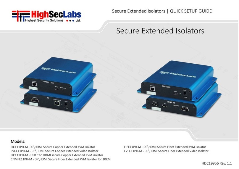
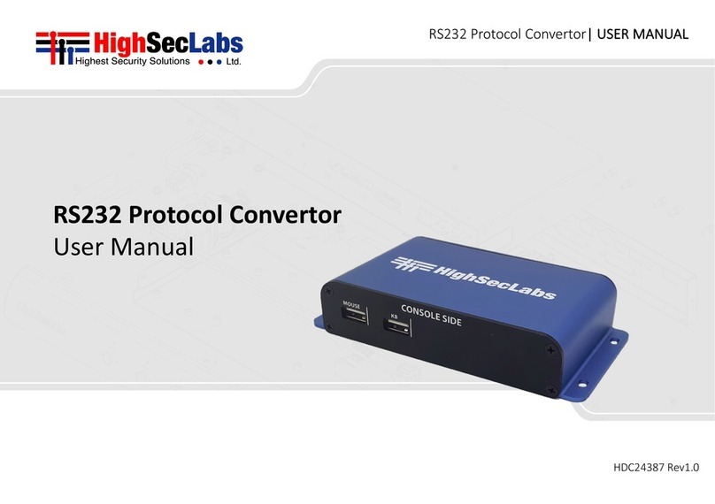
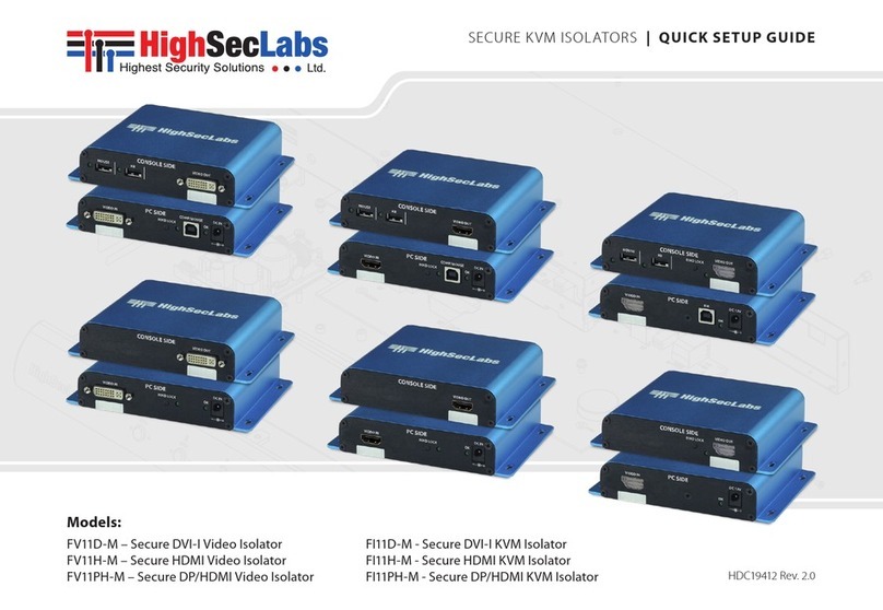
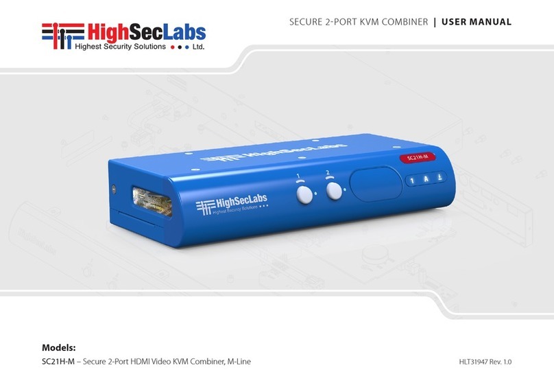
High Sec Labs KM Admin Tool User manual

KVM Remote RS-232 Control | QUICK SETUP GUIDE
Table of Contents SECTIONS 123
HDC21381 Rev. 1.0
KM Admin Tool | USER MANUAL
KM Admin Tool
User Manual

KM Admin Tool | USER MANUAL
TABLE OF CONTENTS
2
Introduction
3
Creating a Custom Layout File Using the KM Admin Tool
4
Uploading a Custom Layout File Using the KM Loader Tool
5

KM Admin Tool | USER MANUAL
INTRODUCTION
The High Sec Labs (HSL) KM switch is a solution for users, like
financial traders or command & control operators, who need
to avoid:
•Constantly switching from one display to another (KVM),
by letting them view multiple computers simultaneously
•Juggling between multiple mice and keyboards, by
enabling them to switch control between computers with
only one mouse and keyboard set
The KM supports any display layout defined by the user. This
enables users to align displays in in any physical layout they
want and configure the KM to support this layout.
Layout examples:
Once configured to the desired layout, the KM is set to reflect
the specific layout and display borders. This helps the KM to:
•Associate the mouse cursor with each computer, based on
its respective display position
•Consider all displays as one absolute screen area to enable
Virtual Display Technology (VDT)
3
12
34
1234
1
234
1
234
12345
678

KM Admin Tool | USER MANUAL
INTRODUCTION
4
The KM’s VDT enables automatically switching control from
one computer to another, by sliding the mouse cursor over
the computer’s display border. The other shared peripherals
(keyboard, audio, USB) move to the next computer, once the
mouse cursor passes the display border. The VDT eliminates
the need to press the front-panel buttons.
Many of the VDT layouts can be quickly set, using the
following table of pre-configured keyboard shortcut presets:
However, if the desired layout does not appear in the table
above, it is necessary to use the KM Admin Tool to create it.
The purpose of this manual is to explain how to use the KM
Admin Tool to set custom layouts.
Using the admin tool requires several steps:
•Create a config file representive of the user’s requested
screen layout
•Loading the config file on the target KM switch
•Directing the KM switch to use the config file loaded.

KM Admin Tool | USER MANUAL
Creating a Custom Layout File Using the KM Admin Tool
5
As stated earlier, a display layout that does not appear in the
table of presets, needs to be created. The first step is to create
a custom layout file using the KM Admin Tool.
This procedure uses the following custom layout example:
This layout consists of three computers, as follows:
•In the top row are Computer #1, on the left and Computer
#2, on the right.
•In the bottom row are two displays of Computer #3,
including the:
oSecondary display, on the left, AND –
oPrimary display, on the right
In this example, the:
•Size of all displays is 24”
•Resolution of all displays is 1920 x 1080
To create a custom layout file:
1. On an Admin PC, from the following link:
http://www.highseclabs.com/support/downloads/?rid=1,
download and install the KM Admin Tool.
This creates the KMC Creator icon on the desktop.
2. Double-click on the KMC Creator icon.
The KM Configuration Utility dialog opens:
Note: Before creating a custom layout file, make sure to note the
screen size and resolution of all monitors to be connected to the KM.

KM Admin Tool | USER MANUAL 6
3. Click Create Project.
The KM Project Setup dialog opens:
4. Fill in the General Setup fields.
•Project Name: Use a descriptive name. In this
example, PCs 1 and 2, single display. PC 3, dual
display.
•Product Model: The product model can be found
on the back sticker of the KM switch. In this
example, select K304 (4-port KM).
•Mouse Speed: Makes mouse movements faster or
slower. In this example, select 5 –Default.
•Mouse Acceleration: Makes mouse accelerate faster or
slower. In this example, select 5 –Default.
•Number of computers: In this example, type 3.
Creating a Custom Layout File Using the KM Admin Tool
Note:
oK304 represents all 4-port switches.
oK308 represents all 8-port switches.
o2-port switches cannot be configured.

KM Admin Tool | USER MANUAL 7
5. At the bottom, click Next Step.
The KM Project Description dialog opens:
6. Type a description that explains the custom layout. In
this example, fill out as follows:
7. At the bottom, click Next Step.
The Computer 1 Setup dialog opens:
8. In this example:
•Computer 1 has one display, so for Number of
displays, select 1
•The display is 24” in diagonal, so for Display 1,
type 24
•The Display Resolution (H/V) is 1920 (horizontal) x
1080 (vertical) resolution, so type 1920 and then
1080
Creating a Custom Layout File Using the KM Admin Tool

KM Admin Tool | USER MANUAL 8
Fill out as follows:
9. At the bottom, click Next Step.
The Computer 2 Setup dialog opens:
10. In this example, fill out like for Computer 1, as follows:
11. At the bottom, click Next Step.
The Computer 3 Setup dialog opens:
Creating a Custom Layout File Using the KM Admin Tool

KM Admin Tool | USER MANUAL
12. In this example, Computer 3 has two displays, the first for
the primary display and the second for the secondary
display. So, in the Number of displays field, select 2.
Two rows for entering the display parameters open.
In addition to the Display Diag and Display Resolution
(H/V) parameters, are the MS H/V Coordinates. The MS
H/V Coordinates enable setting the position of the
primary display relative to the secondary display.
9
Creating a Custom Layout File Using the KM Admin Tool
Note: Due to an error, the dialog shows MS V/H Coordinates instead of
MS H/V Coordinates. When entering these coordinates, use the H/V
order.
Note: To set the MS H/V Coordinates, use the following diagram:

KM Admin Tool | USER MANUAL
The following examples show how to make the MS H/V
Coordinates settings for different primary-secondary relative
positions:
Left
If the secondary display (=1920 x 1080) is to the LEFT of the
primary display, type the SECONDARY display’s HORIZONTAL
value as: (minus) -1920 and the VERTICAL value as: 0.
Right
If the secondary display is to the RIGHT of the primary display
(=1920 x 1080), type the PRIMARY display’s HORIZONTAL
value as: (plus) 1920 and the VERTICAL value as: 0.
Above
If the secondary display (=1920 x 1080) is ABOVE the primary
display, type the SECONDARY display’s HORIZONTAL value as:
0 and VERTICAL value as: (minus) -1080.
Under
If the secondary display is UNDER the primary (=1920 x 1080),
type the PRIMARY display’s HORIZONTAL value as: 0 and
VERTICAL value as: (plus) 1080.
10
Creating a Custom Layout File Using the KM Admin Tool

KM Admin Tool | USER MANUAL
13. In this example, fill in as follows:
•For Display 1 (Primary), type 24 for Display Diag and
1920 and 1080 for Display Resolution (H/V). The MS
H/V Coordinates for Display 1 (Primary) are: 0 and
0. This is because their point of reference is the
starting point, at the top left corner of the primary
display.
•For Display 2 –the secondary display –type 24 for
Display Diag and 1920 and 1080 for Display
Resolution (H/V). The secondary display is to the
LEFT of the primary display, so, for Display 2, type
the SECONDARY display’s HORIZONTAL value as:
(MINUS) -1920 and the VERTICAL value as: (PLUS) 0.
14. At the bottom, click Next Step.
The Place the displays dialog opens, showing all
computers configured:
15. Using the mouse cursor, drag the displays to look like the
desired layout. Note: When dragging each display to its
adjacent display, make sure it turns red. Then, move it
backwards so that it “sticks”, without being red.
In this example, it should look as follows:
11
Creating a Custom Layout File Using the KM Admin Tool

KM Admin Tool | USER MANUAL
16. At the bottom, click Complete Setup.
The Browse for Folder dialog opens:
17. Select a folder to save the file to, and note this location
for future reference.
12
Creating a Custom Layout File Using the KM Admin Tool

KM Admin Tool | USER MANUAL
This procedure shows how to upload the custom layout file,
created in the previous procedure, to the KM.
Required Hardware:
•An Admin PC running Windows 7/8/10 OS
•A HighSecLabs KM (in this example, the 4-port SM40N-3)
•An A-A USB cable
•Standard keyboard
Required Software:
•KM config file (.KMC) created in the previous procedure
•KM Loader Tool ver. 1.0.0.5
To upload a custom layout file:
1. Power on the KM and connect it to the Admin PC.
2. Connect an A-A cable between a vacant USB port on the
Admin PC and the KM console’s mouse port. Note: If that
doesn’t work, connect to the keyboard port.
3. Connect the keyboard to the KM console’s keyboard or
mouse port (this “talks” directly to the KM).
4. Press LEFT CTRL | RIGHT CTRL | Lto enter loading mode.
The LEDs start flashing.
5. On the Admin PC, from the following link
http://www.highseclabs.com/support/downloads/?rid=1
9, download and install the KM Loading Tool.
This creates the KM Loading Tool icon on the desktop.
6. Double-click on the KM Loading Tool icon.
The KMConfigLoader dialog opens:
13
Uploading a Custom Layout File Using the KM Loader Tool
Note: An admin PC is only needed for the initial configuration
of the KM with a kmc file. Once configured the KM can be
disconnected and used by a user without an admin PC.

KM Admin Tool | USER MANUAL
7. Click Browse and locate and select the .KMC
configuration file created in the previous procedure.
8. From the Select COM port list, select the COM.
9. From the Select port configuration list, select the KM’s
number of ports. In this example, select 4.
10. Click Process.
11. Power cycle the KM.
12. Press LEFT CTRL | LEFT CTRL | F11 | F12 to apply the new
settings.
13. If any of the computers in the custom layout have a
primary and secondary display, from the following link:
http://www.highseclabs.com/support/downloads/?rid=1
9, download and install the KM Multi Display Drivers
onto the relevant computers. In this example, install the
KM Multi Display Drivers onto Computer 3 (it has a
primary and secondary display).
14. Power cycle and test that the mouse properly switches
control between adjacent displays in the configuration.
14
Uploading a Custom Layout File Using the KM Loader Tool
Note: Make sure the correct COM port is selected. To locate
the correct COM port, on the Admin PC, right-click on This PC
and select Manage. Under Computer Management, select
Device Manager. In the window that opens, click on the
arrow next to Ports (COM & LPT) and locate the port that is
connected to the KM.

KVM Remote RS-232 Control | QUICK SETUP GUIDE
Table of Contents SECTIONS 123
©2019 All rights reserved. HSL logo and product names are trademarks or service trademarks of HighSecLabs Ltd (HSL). All other marks are the property of
their respective owners. Images for demonstration purposes only. This document may contain confidential and/or proprietary information of HSL
Corporation, and its receipt or possession does not convey any right to reproduce, disclose its contents, or to manufacture or sell anything that it may
describe. Reproduction, disclosure, or use without specific authorization from HSL Corporation is strictly prohibited.
Highseclabs.com
Other High Sec Labs Network Hardware manuals
