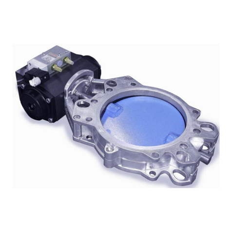
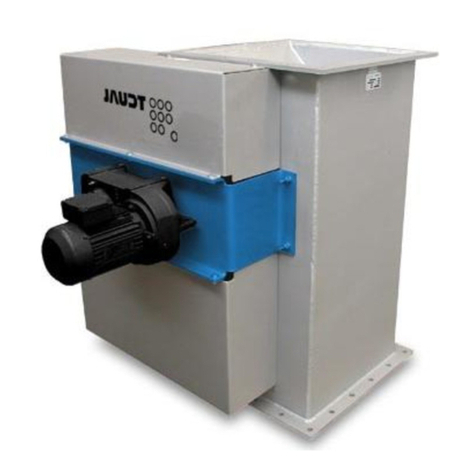
JAUDT FS140-6115 Series Quick guide

Translation of the original operating instructions
JAUDT BH 140 and BH 100 SLIDE VALVES
FS140 - 6115... / FS100 - 6116...
© BA_FS140+100_EN_Rev02-2010.doc
Contents
1DESCRIPTION......................................................................................................................2
1.1 Products to which this instruction manual applies .........................................................2
1.2 Identification plate..........................................................................................................2
1.3 Other applicable documents ..........................................................................................2
1.4 Technical conditions for operation .................................................................................3
2SAFETY INSTRUCTIONS ....................................................................................................3
2.1 Areas of application .......................................................................................................3
2.2 Noise emissions.............................................................................................................4
3TRANSPORT AND STORAGE.............................................................................................4
3.1 Transport........................................................................................................................4
3.2 General storage instructions..........................................................................................4
4INSTALLATION, START-UP, OPERATION.........................................................................4
4.1 Installation......................................................................................................................4
4.2Start-up ..........................................................................................................................7
4.3 Operation .......................................................................................................................7
5MAINTENANCE....................................................................................................................8
6INSPECTION AND MAINTENANCE ....................................................................................8
6.1 Servicing the packing gland...........................................................................................9
6.2 Drive with electric motor...............................................................................................10
6.3 Electropneumatic drive.................................................................................................10
6.4 Hydraulic drive .............................................................................................................10
7DRIVES...............................................................................................................................11
8ACCESSORIES ..................................................................................................................11
9SPARE PARTS...................................................................................................................12
10 ORDERING SPARE PARTS ...........................................................................................15
11 TROUBLESHOOTING ....................................................................................................15
12 CLEANING......................................................................................................................16
13 DISPOSAL ......................................................................................................................16
14 DIMENSION SHEETS FOR STANDARD MODEL..........................................................17
15 DECLARATION OF INCORPORATION..........................................................................19
16 ACCESSORIES...............................................................................................................20
JAUDT
Dosiertechnik
Maschinenfabrik
GmbH
Metering, feeding,
removal, shutting off,
regulating and controlling
Raiffeisenstraße 3-5
D-86167 Augsburg
Tel. +49 821 796 05-0
Fax +49 821 796 05-67
+49 821 796 05-69
www.jaudt.de

Instruction Manual FS140 and FS100 - 6115... / 6116...
© BA_FS140+100_EN_Rev02-2010.doc Page 2 of 20
1 Description
JAUDT slide valves are used to stop and meter substances which are transported in pipes. They are
produced in the highest possible quality using state-of-the-art production processes. They are hard-wearing,
tight-closing and require very little maintenance!
1.1 Products to which this instruction manual applies
This instruction manual applies to JAUDT slide valves of all nominal widths of
overall height 140 type 6115... and
overall height 100 type 6116...
which are actuated in the following ways:
Manually by means of a hand crank, hand wheel, ratchet or chain
Electric motor
Electropneumatic drive
Hydraulic cylinder
1.2 Identification plate
A nameplate is attached to every JAUDT slide valve:
The machine number does not specify the coating or accessory equipment.
Please quote both numbers (type number and order no.) whenever ordering spare parts or making enquiries.
1.3 Other applicable documents
The order confirmation is a constituent part of this instruction manual. It lists the following information:
Model, identical with the model on the nameplate.
Designated application; the design of the slide valve will be customised to this application.
Technical data relating to slide valve and, where applicable, technical data relating to drive.
The following additional documents are appended to every instruction manual:
Dimension sheet.
Manual incl. lubrication chart for motor (if supplied with motor).
Data sheet for limit switch or solenoid valve (if supplied with limit switch or solenoid valve).
ATEX insert if required to conform to RL94/9/EC or if used in areas at risk of explosion.
These enclosures and appendices form a constituent part of this instruction manual!

Instruction Manual FS140 and FS100 - 6115... / 6116...
© BA_FS140+100_EN_Rev02-2010.doc Page 3 of 20
1.4 Technical conditions for operation
The slide valve must be securely enclosed in order to protect against injury. If this enclosure was not ordered
with the slide valve or if the slide valve is modified by the operator then it is essential to comply with the
regulations set out in the Machine Directive. JAUDT supplies enclosures which can be adapted to the
different requirements.
Providing the necessary supply voltages:
Information on voltage requirements can be found in the chapters relating to drives and accessories or in the
other applicable documents.
Providing a supply of compressed air:
Electropneumatic drive: 0.7...1.1 MPa (7...11 bar absolute), filtered and free of water. An oil-lubricated air
compressor is recommended to optimise the service life of the seals.
Providing hydraulic fluid:
Hydraulic drive: 18 ... 21 MPa operating pressure
2 Safety instructions
Take measures to ensure that local accident prevention regulations are observed.
Before starting to do any work on the JAUDT slide valve, take the necessary steps to make sure that the drive
unit is switched off/disconnected and that the appropriate control staff have been informed about the work. If
aggressive or hot substances are being stopped by the JAUDT slide valve, suitable safety precautions must
be taken before work on the slide valve begins. These include wearing protective clothing, using breathing
apparatus and positioning collection containers.
Where applicable, the safety officer and/or the environmental protection officer must be informed before work
begins.
The slide valves conform to the latest standards of science and technology. Nevertheless, personal
injury and damage to property can occur due to carelessness. We provide warnings in the form of
appropriate information. This information is flagged up by special symbols.
Caution! Danger of death!
This sign draws attention to a potentially life-threatening situation caused by electrical
connections.
Caution! Danger of injury!
This sign draws attention to a potentially life-threatening situation.
Caution! Damage to property!
This sign draws attention to an action which might cause damage to the JAUDT slide
valve.
•
A bullet point indicates a sequential action.
Extreme care must be taken to carry out the necessary steps in the right order.
2.1 Areas of application
In their standard configuration, JAUDT slide valves are suitable for free-flowing, powdery to fine-
grained loose products with grains up to 3 mm in size. We can provide expert advice if you need
equipment for different applications.

Instruction Manual FS140 and FS100 - 6115... / 6116...
© BA_FS140+100_EN_Rev02-2010.doc Page 4 of 20
2.2 Noise emissions
The level of noise emissions is 85 dB (A).
3 Transport and storage
3.1 Transport
Transport the slide valve lying on its discharge flange.
Secure the slide valve properly to prevent it from suffering shocks and blows and protect the coating by
placing suitable elements between the securing tape and the slide valve.
Secure the slide valve to prevent it from slipping and protect the particularly exposed parts such as the
drive unit and accessories.
3.2 General storage instructions
Store the slide valve lying on its discharge flange.
Protect cables, hoses, drive and mounted accessories from damage.
Storage temperature 10 °C … 30 °C
Max. relative humidity 65%
Store in a dry, dust-free place.
Do not store in a corrosive atmosphere, such as an acidic or saline environment.
The following additional precautions must be taken if the slide valve is to be stored for over three
months:
Protect bare parts from corrosion, e.g. using a film of oil.
Cover the valve to protect it from dust.
Actuate the valve once a year.
Do not store the device for over four years.
The following conditions must be met for storing the glands (as per DIN 7716):
Storage temperature 10 °C … 30 °C
Max. relative humidity 65 %
Store in a dry, dust-free place.
Do not store the glands in an oily or corrosive atmosphere.
Protect from direct sunlight.
Always store horizontally and in their original packaging.
4 Installation, start-up, operation
4.1 Installation
This work may be carried out by appropriately trained installation staff only!
Electrical work must be carried out by trained electricians!
JAUDT slide valves are generally supplied assembled and ready for operation.
Special installation instructions are to be observed in the case of very large slide valves (FS XXL) which are
supplied disassembled.
See relevant documents in appendix.

Instruction Manual FS140 and FS100 - 6115... / 6116...
© BA_FS140+100_EN_Rev02-2010.doc Page 5 of 20
4.1.1 Manually actuated slide valves
Before installation, check whether the slide valve is adjusted correctly. Adjust the setting if necessary:
Check whether the slide valve closes tightly.
Inductive limit switches (optional): check the settings “Slide OPEN” - “Slide CLOSED”.
See section 4.1.3 for information about setting the limit switches.
4.1.2 Pneumatically actuated slide valves
Before a pneumatically actuated slide valve is installed, a check should be made to see that it is working
properly:
Connect the cylinder
Connect the limit switches to the control system
Choose the pneumatic setting “CLOSED” (“ZU”)
The tip of the slide plate may be no further than 5 mm away from the frame
If necessary, the limit switches must be set:
Undo the lock nuts and screw the limit switches in or out until the correct end position has been
reached.
Caution! Damage to property!
Caution: Do not screw the limit switches in too far, otherwise the switching lug will
shear them off.
Caution! Danger of injury!
Caution: Look out for shear point when closing the slide valve.
4.1.3 Motor-actuated slide valves
Before a motor-actuated slide valve is installed, a check should be made to see that it is working properly.
Connect the motor - if using AUMA motors it may be necessary to connect a torque monitor.
Consult the drive manufacturer’s operating instructions!
Connect the limit switches to the control system
Choose the electrical setting “CLOSED” (“ZU”)
The tip of the slide plate may be no further than 5 mm away from the frame
If necessary, the limit switches must be set:
Undo the lock nuts and screw the limit switches in or out until the correct end position has been
reached.
Caution! Damage to property!
Caution: Do not screw the limit switches in too far, otherwise the switching lug will
shear them off.
Caution! Danger of injury!
Caution: Look out for shear point when closing the slide valve.

Instruction Manual FS140 and FS100 - 6115... / 6116...
© BA_FS140+100_EN_Rev02-2010.doc Page 6 of 20
4.1.4 Hydraulically actuated slide valves
Caution! Damage to property!
Limit the maximum operating pressure to 5 Mpa.
Caution! Danger of injury!
Caution: Look out for shear point when closing the slide valve.
Before a hydraulically actuated slide valve is installed, a check should be made to see that it is working
properly:
Connect the hydraulic cylinder
Connect the limit switches to the control system
Choose the “CLOSED” setting (“ZU”)
The tip of the slide plate must not be struck on its face and may be no further than 5 mm away from the
frame!
If necessary, the limit switches must be set:
Undo the lock nuts and screw the limit switches in or out until the correct end position has been
reached.
Caution! Damage to property!
Caution: Do not screw the limit switches in too far, otherwise the switching lug will
shear them off.
4.1.5 Installation position
JAUDT slide valves are designed to be installed horizontally. If a different installation position is
required, JAUDT should be consulted. Do not install them upside down. The correct installation
position can be seen in section 9 “Spare parts”.
4.1.6 Installation instructions
Clean the flange surfaces.
Apply a flexible sealing material to the flanges (neoprene, silicone, etc.).
Caution! Damage to property!
Do not apply force when installing the JAUDT slide valve otherwise there is a danger
that the equipment will be damaged.
It is essential to follow the installation instructions below.
Align the JAUDT slide valve with the pipes.
Align the flanges so that they are plane-parallel.
Tighten the connecting elements diagonally. Do not exceed max. tightening torque of 100 Nm
(screws M16).

Instruction Manual FS140 and FS100 - 6115... / 6116...
© BA_FS140+100_EN_Rev02-2010.doc Page 7 of 20
4.2 Start-up
This work may be carried out by appropriately trained installation staff only!
Electrical work must be carried out by trained electricians!
After it has been installed, check the JAUDT slide valve by actuating it a few times to make sure:
that the slide moves quietly and easily
that there are no leaks
that the attachment elements have been tightened securely.
In the case of power-actuated versions, the following checks should also be carried out:
Caution! Danger of injury!
Make sure that the equipment has been switched off and that precautions have been
taken to prevent it from starting up again automatically.
Inform the appropriate control staff.
Check that the electropneumatic equipment is working properly and is tight.
Activate the lubricator on the spindle nut (standard on motor-driven model) by turning the relevant screw
on the lubricator. –Data sheet lubricant sensor see appendix A3
Check the electric motor and the limit switches to see if they are connected properly.
The control system at the installation location must switch the slide valve off when it reaches the end
positions, in response to the signal issued by the limit switches.
Caution! Damage to property!
Overriding the limit switches may cause permanent damage to the slide valve!
4.3 Operation
Manual:
The slide valves are designed to move easily. The crank has to be turned until the stop is reached at both
end positions.
Pneumatic:
Actuation by means of an electric signal to the solenoid valve or a manual emergency stop on the valve.
Motor:
Actuation by the control system at the installation location.
Hydraulic:
Actuation by the control system / hydraulic valves at the installation location.

Instruction Manual FS140 and FS100 - 6115... / 6116...
© BA_FS140+100_EN_Rev02-2010.doc Page 8 of 20
5 Maintenance
Maintenance includes servicing, inspection and repairs.
Repairs may be carried out by JAUDT GmbH only.
Servicing and inspection must be carried out by appropriately trained personnel.
Electrical work must be carried out by trained electricians.
Inspection
Every 3 months
Servicing
Every 3 months
In constant operation or critical working conditions
Every 6 months
In all other cases
Adhere to inspection and servicing intervals specified for parts from other suppliers - see “Other
applicable documents” (section 1.3).
6 Inspection and maintenance
The inspections have to be carried out at the same time as the servicing work.
Identifies the inspection and servicing work
Caution! Danger of injury!
Make sure that the equipment has been switched off before starting work and
that precautions have been taken to prevent it from starting up again
automatically. Inform the appropriate control staff.
Caution! Danger of injury!
Wear protective clothing, safety goggles and breathing apparatus when
metering substances which are hot or which irritate the skin.
Inform the safety and environmental protection officers.
Keep a suitable collection container close at hand.
Caution! Danger of death!
Make sure that the drive unit is switched off or disconnected.
Make sure that the equipment has been switched off before starting work and
that precautions have been taken to prevent it from starting up again
automatically. Inform the appropriate control staff.
For illustrated assembly instructions please refer to “Spare parts” (section 9).
Check that the attachment elements are tightened securely. Remove any dirt and rust.
Make a visual check. Replace any damaged parts wherever necessary.
Check whether the slide valve is tight.
Check whether the slide valve moves easily and quietly.
Lubricate with hand operated slide valves the spindle with chain grease or other kinds of standard
grease. Enclosed slide valves have a screw on top that needs to be unscrewed and removed to permit
lubrication.
Check and replace with motor operated slide valves the lubricant sensor. –Data sheet lubricant sensor
see appendix A3
Take the slide valve apart and clean it if material is caked on.
Replace the self-locking nuts every time you do this.
The maintenance work that has to be done on stuffed packing is described in the following sections.

Instruction Manual FS140 and FS100 - 6115... / 6116...
© BA_FS140+100_EN_Rev02-2010.doc Page 9 of 20
6.1 Servicing the packing gland
6.1.1 Replacing the packing gland
Empty the silo
Move the slide plate (20) to the "CLOSED"
position
Unscrew side cover (50)
Undo screws (90) on pressure part (80)
Remove pressure pad (70) from the side or
towards the rear
Remove the seals (60).
Fit new seal elements 20x15xl (60)
Attach side seal elements 20x15x38 (61, 53)
and fit side cover.
Tighten the screws on thrust piece (80),
retighten if any leaks occur
6.1.2 All-round gasket in valve opening (optional)
When the all-round gasket starts to become less efficient, it can be adjusted by tightening the screws. Tighten
them by turning each of them half a revolution as equally as possible.
Replacing the gasket:
Move the slide valve to the “OPEN” position
The bottom flange must be easily accessible
Loosen the screws holding the clamping
plates (130, 135, 140), but do not remove
them as this will cause the clamping plates to
fall out
Remove the gasket 145)
Fit new gasket; it must be flush with the slide
plate (20)
Tighten the screws with the sealing rings
Actuate the slide valve once a month to check
it.

Instruction Manual FS140 and FS100 - 6115... / 6116...
© BA_FS140+100_EN_Rev02-2010.doc Page 10 of 20
6.2 Drive with electric motor
Electrical work must be carried out by trained electricians.
Check the electric motor drive unit. If it runs noisily, replace the ball bearing between the gear unit and
the spindle if necessary.
Lubricate the spindle with chain grease or other kinds of standard grease. Enclosed slide valves have a
screw on top that needs to be unscrewed and removed to permit lubrication.
Check and replace with motor operated slide valves the lubricant sensor. –Data sheet lubricant sensor
see appendix .
Check the electrical connection for signs of oxidation, damage or leaks.
Check that the limit switches are working properly and are in good technical condition.
Make sure that the safety guard (cover plate) is attached securely.
6.3 Electropneumatic drive
Electrical work must be carried out by trained electricians.
Check the pneumatic supply system and drain it if necessary.
Make sure that the magnetic valves are working properly.
Check whether there are any leaks in the pneumatic system.
Check that the limit switches (optional) are working properly and are in good technical condition.
Make sure that the safety guard is attached securely.
The cylinder liner of the electropneumatic drive features different diameters ØD depending on the nominal
width of the slide valve.
Tabular overview of repair kit for JAUDT electropneumatic drive:
6.4 Hydraulic drive
Inspection and maintenance must be carried out in accordance with the manufacturer's specifications
for the hydraulic cylinder (see insert).
ØD
A
Repair kit article number
125
M20x1,5
601108
160
M30x1,5
601109
200
M30x1,5
416610.0107

Instruction Manual FS140 and FS100 - 6115... / 6116...
© BA_FS140+100_EN_Rev02-2010.doc Page 11 of 20
7 Drives
The following pages feature diagrams of the JAUDT slide valve with a hand crank, an electric motor and an
electropneumatic drive.
The other drive configurations are assembled in the same way as the drive with the hand crank.
Drive with hand wheel or
ratchet
As for drive with hand crank
Drive with sprocket wheel
As for drive with hand crank. The chain must be guided through
both hooks.
8 Accessories
Limit switch inductive
JAUDT 6115... and 6116... slide valves can be fitted with limit switches to report “OPEN - CLOSED”
positions.
The limit switches are preset at the factory. Their setting must be checked during the commissioning
process and adjusted if necessary.
5/2 way solenoid valve (with pneumatic unit)
230 V AC or 24 V DC/48 V AC
The technical data sheets relating to the accessories are appended to this operating manual!

Instruction Manual FS140 and FS100 - 6115... / 6116...
© BA_FS140+100_EN_Rev02-2010.doc Page 12 of 20
9 Spare parts
Height 140 slide valve - type 6115...

Instruction Manual FS140 and FS100 - 6115... / 6116...
© BA_FS140+100_EN_Rev02-2010.doc Page 13 of 20
Spare parts for height 100 slide valve - type 6116...

Instruction Manual FS140 and FS100 - 6115... / 6116...
© BA_FS140+100_EN_Rev02-2010.doc Page 14 of 20
Detail Optional
Packing gland: All-round gasket:
Optional
Wiper in packing
Names of spare parts:
20
Slide plate
115
Lubricator
240
Limit switch
30
Roller / screw
120
Spindle lug
245
Terminal box
40
Cover plate
125
DU liner
300
Pneumatic cylinder / hydraulic cyl.
50
Packing cover
130
Tension bar front
301*
Cylinder repair kit
53*
O-ring
135
Tension bar right
310
Solenoid valve
60*
Packing
140
Tension bar left
320
Piston rod mounting
61*
Packing
145*
Packing all-round
400
Hand wheel
62*
Wiper
150
Spindle bearing housing
410
Chain wheel
63*
Packing cord
151*
O-ring
411
Chain
70
Pressure pad
152*
O-ring
412
Chain guide
80
Pressure part
155
Spindle bearing
413
Swing hook
90
Set screw
160
Clutch housing
420
Hand crank
100
Spindle
170
Clutch
430
Ratchet + accessories
110
Spindle nut
220
Limit stop
500
Motor
*) = Part subject to wear

Instruction Manual FS140 and FS100 - 6115... / 6116...
© BA_FS140+100_EN_Rev02-2010.doc Page 15 of 20
10 Ordering spare parts
If you have a JAUDT customer number you can also order spare parts via the website at www.jaudt.de.
Please give us the following information when ordering spare parts:
Name, item and article number from the spare parts list (appendix)
Order no. and type of JAUDT slide valve as specified on the type plate.
Example:
You need e.g. a new slide plate. We need the following details:
Slide plate, item 20
Order no. according to nameplate, e.g. 208-1234
Type according to nameplate, e.g. 208-1234.10
11 Troubleshooting
Fault
Cause
Remedy
Slide plate leaking outwards
Packing glands worn
Packing glands not leak-tight
Slide plate worn or affected by
caked-on materials
Improper use
Replace packing glands
Tighten packing glands
Clean or replace slide plate
Check working conditions (e.g.
pressure and temperature)
Leak in opening on slide plate
Caking on slide plate or housing
Seal in opening worn (where
fitted)
Improper use
Clean
Fit new seal
Check working conditions (e.g.
pressure and temperature)
Slide plate jerking or not
moving
Caking on slide plate incl. guides
or in housing
Packing glands worn or subject to
excessive tension
Drive or power supply and control
unit defective
Clean
Replace or adjust packing
gland
Check and repair
Pulse generator not emitting
any signals
Pulse generator defective
Loose actuating element or
incorrect setting of pulse
generator
End positions are not being
reached
Renew
Check and adjust
Remove caking or foreign
bodies; check drive and power
supply

Instruction Manual FS140 and FS100 - 6115... / 6116...
© BA_FS140+100_EN_Rev02-2010.doc Page 16 of 20
12 Cleaning
Do not use cleaning agents containing acid and alkaline solutions.
Foodstuffs:
If food is being metered, clean the JAUDT slide valve under running drinking water with a soft brush.
If heavily soiled, use commercially available detergents. Make sure that these detergents are not toxic and do
not form toxic compounds. Make sure that they contain no acids and alkaline solutions.
Rinse with plenty of drinking water.
13 Disposal
Used oil and lubricants are classified as hazardous waste. Please dispose of them in an environmentally
acceptable manner.

Instruction Manual FS140 and FS100 - 6115... / 6116...
© BA_FS140+100_EN_Rev02-2010.doc Page 17 of 20
14 DIMENSION SHEETS FOR STANDARD MODEL
(See appendix for other models)
JAUDT FS140 slide valve type 6115...

Instruction Manual FS140 and FS100 - 6115... / 6116...
© BA_FS140+100_EN_Rev02-2010.doc Page 18 of 20
JAUDT FS100 slide valve type 6116...

Instruction Manual FS140 and FS100 - 6115... / 6116...
© BA_FS140+100_EN_Rev02-2010.doc Page 19 of 20
15 DECLARATION OF INCORPORATION
within the meaning of EU Directive 2006/42/EC, Annex II Part 1.B
Manufacturer, address JAUDT Dosiertechnik
Maschinenfabrik GmbH
Raiffeisenstr. 3 - 5
86167 Augsburg
Tel. ++49 (0)821 79605-0
Documentation officer Wolfgang Morell, JAUDT Dosiertechnik GmbH
Product denomination / Device Type Slide valve / 6115…, 6116…
The above partly completed machinery is governed by the requirements of Directive 2006/42/EC
Annex I, its general principles and its Part 1 and where appropriate Point 2.1. If used in areas at
risk of explosion Directive 94/9/EC (ATEX) also applies.
The fundamental requirements 1.3.3 and 1.3.4 can be ensured. The above requirements can only
be ensured through proper installation.
In addition, the above product conforms in the supplied version to the provisions of Directive
2006/95/EC “Low Voltage Directive” and 2004/108/EC “Electromagnetic Compatibility”.
For the purposes of assessment of conformity the manufacturer produced the special technical
documentation pursuant to Directive 2006/42/EC Annex VII Part B. This documentation will be
sent to the authorities of the individual member states in file form on justified request.
The above partly completed machinery is intended solely for incorporation in another machine.
Commissioning is prohibited until it has been ascertained that the machine / system into which the
partly completed machinery is to be incorporated meets the requirements of all the above
directives.
JAUDT Dosiertechnik GmbH
Raiffeisenstraße 3-5 Robert Roßkopf
D-86167 Augsburg Managing Director
Augsburg, 21.05.2010

Instruction Manual FS140 and FS100 - 6115... / 6116...
© BA_FS140+100_EN_Rev02-2010.doc Page 20 of 20
16 Accessories
On the following pages the technical data sheets or the documentation of the accessories are specified.
This manual suits for next models
1
Table of contents
Other JAUDT Control Unit manuals