Highlander iP-2 User manual

The information and graphics contained in this document are the property of Highlander Musical Audio Products. Copying of any kind is prohibited, except for personal use only. © Highlander Musical Audio Products 1991-2009
For more information please visit our web site.
email: [email protected]
Contact us at:
USA & Canada Toll Free: 888.658.1819, Phone: 805.547.1410, Fax: 805.547.1228
870 Capitolio Way, Unit 3, San Luis Obispo, CA 93401
Dual System - Integrated Pickup and Preamp for Acoustic Guitar and Bass
Dual System - Integrated Pickup and Preamp for Acoustic Guitar and Bass
h
ighlanderpickups.com
ighlanderpickups.com
Thank you for purchasing the Highlander iP-2 Integrated Pickup System.
At Highlander we appreciate that it takes years of practice, dedication and personal growth
for an acoustic musician to develop the skills and spirit necessary to express themselves fully
through their music. Through years of practice, dedication and personal growth our highly
skilled team is crafting amplification equipment for these musicians that is so pure, we can all
fully appreciate and be moved by the true spirit of their music.
Built to take the rigors of the road, you can rely on a Highlander.
For optimum pickup pe
For o ptim um pic kup pe
rf
rf
ormance and ease of installation, please take a
orm ance a nd eas e of ins tall atio n, ple ase ta ke a
moment to read through this Installation Guide before beginning. Thank You.
moment to read through this Installation Guide before beginning. Thank You.
iP-2 INSTALLATION
iP-2 INSTALLATION
THIS INSTALLATION SHOULD ONLY BE UNDERTAKEN BY AN EXPERIENCED LUTHIER
THIS INSTALLATION SHOULD ONLY BE UNDERTAKEN BY AN EXPERIENCED LUTHIER
OR A GOOD WOODWORKER WITH EXPERIENCE WORKING ON ACOUSTIC STRINGED INSTRUMENTS.
OR A GOOD WOODWORKER WITH EXPERIENCE WORKING ON ACOUSTIC STRINGED INSTRUMENTS.
Using the wrong techniques or tools could result in permanent damage to your guitar.
Highlander is not responsible for any damage resulting from the installation of this pickup system.
Parts Included:
Qty. Description
1 Pre-wired iP-2 Pickup/Preamp Assembly with an Access Jack
For connecting a 2nd source
2 Battery Holder Clips for 9 Volt Battery
3 Pieces of Self Adhesive Velcro® for cable strain relief
1 Stereo Mini-Plug for connecting a second transducer to the iP-2
Tools Required:
1) HAND DRILL or ELECTRIC DRILL (cordless preferred)
2) MILLING MACHINE or ROUTER AND SADDLE SLOTTING JIG
Used for routing the groove
3)* 17/32" (13.5mm) DRILL BIT, RELIEVED ON RAKE EDGES
Used for drilling guitar end block for the strap jack
4)* 9/16"-12 TPI NC TAP & MACHINIST'S TAP HANDLE
Used for threading end block to accept the strap jack
5)* 1/16" (1.6mm) DIAMETER BALL ENDED END MILL
Used for routing the groove in the bottom of the saddle slot
6) 3/32" (2.5mm) TWIST DRILL BIT
Used for drilling both holes in the saddle slot for the pickup
7) MILLING MACHINE or DISC / BELT SANDER or
MACHINIST'S VISE AND FILE. STRAIGHT EDGE
Used for reducing saddle height to
compensate for the pickup thickness
* The following installation tools are available from Highlander:
17/32" drill bit
9/16"-12TPI tap bit
1/16" router bit
These tools are available individually or as the 'iP-installation kit'
The information and graphics contained in this document are the property of Highlander Musical Audio Products. Copying of any kind is prohibited, except for personal use only. © Highlander Musical Audio Products 1991-2009
The 2nd source is hard wired
from the Tip of the Access Jack
to the Ring on the Output Jack.
The iP-2 does not include a 2nd
preamplifier for the 2nd source.
Output Jack
Tip: Pickup and Preamp Out
Ring: 2nd Source Out
Shield: Ground
This innovative screw thread is designed
to stay in place regardless of variations in
the end block as it expands and contracts
due to humidity and temperature changes.
By eliminating the typical machine thread
and nut, our preamp will never come loose
and require the awkward task of tightening
a nut at the end pin block inside the guitar.
The elegant strap button holds the strap
securely and will never untwist or loosen.
The iP-2 is turned on when a guitar cord is plugged in
and turned off when it is unplugged, saving the battery.
For more information check out our web site: highlanderpickups.com
ighlanderpickups.com
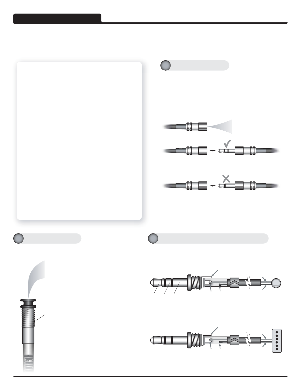
Tip Shield Shield
Ring must be left open
(unconnected)
Hot
Magnetic
Pickup
Tip Ring Tip Shield Shield
Sleeve
Ring must be left open
(unconnected) Electret
Condenser
Mic
Hot
Wiring for a Phantom Powered, Electret Microphone.
Wiring for a Phantom Powered, Electret Microphone.
Wiring for a Passive Magnetic, Sound Hole Pickup.
Wiring for a Passive Magnetic, Sound Hole Pickup.
Never use a Mono Male to connect to the Access Jack.
Never use a Mono Male to connect to the Access Jack.
+9 Volt power on the ring will be shorted out causing the battery
+9 Volt power on the ring will be shorted out causing the battery
to seriously overheat.
to seriously overheat.
If this inadvertenlty happens during installation, the battery has been
compromised and must be changed.
A High Quality 3.5mm Stereo Male is provided with every iP-2.
Always Use a Stereo Male to connect to the Access Jack.
Always Use a Stereo Male to connect to the Access Jack.
When connecting a mono source, the stereo plug must still be used
with the ring left unconnected.
Tip: 2nd Source Audio
Ring: +9 Volt for 2nd Source
Shield: Ground
The Access Jack (AJ) is a 3.5mm Stereo Female Jack that enables a
2nd Source to be used with the iP-2 including a magnetic sound hole
pickup or an electret microphone such as our 'Internal Mic' . Power for
active pickups or electret microphones is provided on the ring of the AJ.
The power at the AJ is 'on' only when the guitar is plugged in.
Both signals are available separately at the output Jack, enabling both
sources to be connected to separate sound systems or amplifiers.
Both signals can be combined using a good quality mixer such as our
'Pro Acoustic Mix DI'.
About the Output Jack Typical wiring for the 3.5mm Stereo Mini Jack
About the Access Jack

0.065" (1.65mm)
0.050”
(1.3mm)
3/32" Hole3/32" Hole
Bridge
Brace
Saddle Slot
Guitar Top Radius corner on both holes
Battery
Clips
The information presented here has been greatly enhanced over the years by listening
to the craftsmen who have installed countless numbers of these pickups. Thank you.
Remove the strings. Lightly scribe a line on the saddle or make a note of the saddle height. This is useful as a guide
when reseating the saddle at the original height. Remove the saddle.
Drill a 17/32” (13.5mm) hole. Be sure to drill at 90º to end block.
Use a relieved bit to avoid wood tear out or end block splitting.
One way to drill a clean hole is to ream out the hole with a tapered reamer until
the drill bit goes 0.1” (2.5mm) into the hole (through the side). Then drill the hole
through the block. Note: Some people run the drill in reverse.
Thread with a 9/16”-12TPI tap (at 90º to end block).
The performance of the Highlander Pickup is optimized by embedding it in a groove in the bridge. This
‘couples’ the pickup to the sound board of the guitar capturing all of its energy, vitality and nuances.
Velcro®
Velcro®
Velcro®
Preparing the B
Preparing the B
ri
r i
dge
dge
Thoroughly clean the area.
Push both clips onto a 9V
battery and attach the
connector.
Peel the backing off the
clips and press in place
on the back of the
guitar.
Prepare the bridge for the pickup.
See details of ‘Preparing the
Bridge’ below. See details of the
pickup installation
on the next page.
Avoid a sharp bend. It is important that
the pickup is bent around a radius.
If a 90° 'hole angle' is unavoidable then
make the radius as large as possible.
Drill two 3/32” (2.5mm) holes at an angle as shown below. Being careful not to damage the Brace (or other
parts of the structure), try to get as close to a 45° 'hole angle' as possible.
Route a Groove for the pickup using a saddle router jig and router with a 1/16”
(0.0625”) (1.6mm) ball ended cutter. The groove should be 0.05" (1.3mm) deep.
The groove should extend from one 3/32" hole to the other, it should be smooth
and flat. Any irregularities in the groove may cause string imbalance.
The battery position shown in this diagram is one possible placement option. The battery can also be mounted on the neck block.
The actual position will depend on the type of instrument involved, and the needs of the musician using it.
Applying a light coat
of lacquer to the area
where the battery
clips are to be
attached significantly
improves adhesion.
Wait until the lacquer
is fully dry before
applying the clips.
Excess cable is held in place on the back of the guitar with Velcro®. Cables
should be loosely coiled. The Velcro® ensures the cable will not be pinched.
AVOID SHARP BENDS, KINKS or TWISTS IN THE CABLES.
I
t
'
s
a
l
l
i
n
t
h
e
g
r
o
o
v
e
iP-2 INSTALLATION
iP-2 INSTALLATION
The information and graphics contained in this document are the property of Highlander Musical Audio Products. Copying of any kind is prohibited, except for personal use only.
©
Highlander Musical Audio Products 1991-2009
Highlander's 'Internal Mic' plugs
directly in to the Access Jack.
Check out our web site for
information on how to hook up
a variety of mics and pickups.
highlanderpickups.com
Access Jack
End
Block
Velcro the Access Jack in place.
Pass the pickup, battery snap and
Access Jack through the end-pin hole.
Insert the preamp into the end-pin
hole, apply a little wood glue (like
Elmers') to the thread and screw the
preamp into the end-pin hole by hand.
Use a chamois or rubber grip if
necessary. Do not use pliers or
anything similar as the strap nut may
be damaged.
Turn the wires inside the guitar to
prevent twisting.Untwist all the wires
before continuing. Excessive twisting of
the black pickup cable may cause hum.
Route the Pickup Groove
2b
2b
Drill Two Holes for the Pickup
2a
2a
Install Pickup
5
Install 2nd Transducer
6
Install Battery
4
Install Preamp
3
Modification
2
Preparation
1

Installing the Pickup
Installing the Pickup
Consistent String Balance is achieved with this 'Two Hole' installation.
Note: These types of 'Saddle Fits' may sound o.k. acoustically, however, the
saddle needs to be in full contact with the pickup for a good amplified sound
and to insure the best acoustic tone and sustain.
To help maintain the 'Saddle Fit' during variations in humidity and
temperature, lightly wax the bridge and the inside of the saddle slot. Be
sure to remove any excess wax from the slot and especially the groove.
Polishing the sides of the saddle helps create a smooth, sliding fit.
Pass the pickup up through the hole at the 'Low E' side of the bridge and then down through
the hole at the 'High E' side of the bridge.
1
Measure the difference in saddle height using either
the line scribed or the height measured in step .
Trim the difference from the
underside of the saddle.
The underside of the saddle
must be really flat.
Check with a straight edge.
Once the original saddle
height is achieved,
chamfer and debur the
bottom edges of saddle
to help prevent binding.
Check the saddle height.
Using the saddle or a piece of wood, apply just
enough pressure to seat the pickup in the groove.
'Low E' side
The saddle should move freely
up and down in the saddle slot.
Too loose
Too loose
and the saddle can
bind under string tension.
Too tight
Too tight
and the saddle
may not be fully seated.
Pickup
Saddle Material: Micarta®has a consistent density which
helps with string balance. Bone can be inconsistent, when
choosing a piece hold it to a light and look for even color.
The pickup will not function correctly if the tip is placed under the saddle, the tip must be inserted in the hole as illustrated above.
Removing the tip of the pickup or the use of solvents, super glue or lacquer on the pickup will compromise its operation and will void the warranty.
The consistent string balance achieved with this 'two hole' installation technique is due to the mechanical symmetry of having the same type of bend at
each end the pickup. This causes the mechanical forces such as sound vibrations that are acting on the pickup to be well balanced throughout the pickup.
The tip is a special electrically shielded
termination that helps to prevent hum and
interference even when the pickup is used
with an amplifier that is not grounded.
It also makes the pickup easier to handle.
Press the saddle down firmly on to the pickup and replace the strings. Start with the 'D' String. While tensioning it, press the
saddle back (away from the sound hole) and down to prevent the saddle from binding in the saddle slot.
Next, replace the 'G' String then the rest of the strings. Plug in and check the string balance and sound quality of the installation.
If the tip or the crimp comes into contact with
the brace they could vibrate and create an
unwanted sound. A soft pad between them and
the brace (like a piece of double stick foam on
the brace) can prevent any potential problems.
Tip
Crimp
We recommend that
strings be replaced
two at a time from
now on, it will help
maintain the stability
of the installation.
Maintain a small
gap between the
crimp and the top
of the guitar.
The information and graphics contained in this document are the property of Highlander Musical Audio Products. Copying of any kind is prohibited, except for personal use only. © Highlander Musical Audio Products 1991-2009
Install the Pickup in the Groove
5a
5a
Trim and Install the Saddle
5b
5b
Restringing
5c
5c
Check the 'Saddle Fit': This is important information for the correct operation of all under saddle pickups.
5
Pickup
Saddle
Other Highlander Accessories For Musical Instruments manuals


