Highway Equipment Company New Leader MARK V DGPS-Ready Configuration guide

IMPORTANT: READ THE SAFETY GUIDELINES AND ALL INSTRUCTIONS CAREFULLY BEFORE OPERATING
HIGHWAY EQUIPMENT COMPANY – NEW LEADER DIVISION
1330 76TH AVE SW, CEDAR RAPIDS, IOWA 52404-7052
PH. (319) 363-8281 www.highwayequipment.com FAX (319) 632-3081
HIGHWAY EQUIPMENT COMPANY
GENERAL MANUAL FOR MODEL
MARK V
DGPS-READY
SAFETY GUIDELINES
INSTALLATION
OPERATION
TROUBLESHOOTING
PARTS LIST
This machine may have been built with
SPECIAL FEATURES. When ordering
parts, please furnish SERIAL NUMBER.
DEALER ______________


MODEL MARK V DGPS-Ready
SERIAL NUMBER__________________
MANUAL NUMBER: 89008-A
EFFECTIVE 9/2002
HIGHWAY EQUIPMENT COMPANY
1330 76TH AVE SW
CEDAR RAPIDS, IOWA 52404-7052
PHONE (319) 363-8281 FAX (319) 632-3081
www.highwayequipment.com
BUILDING THE BEST SINCE 1939

Please Give Part No., Description and Unit Serial No.
HIGHWAY EQUIPMENT COMPANY
2
89008-A
Page Rev. A
TABLE OF CONTENTS
Warranty.....................................................................................................4
Preface........................................................................................................5
Safety..........................................................................................................6
General Description....................................................................................8
Installation Instructions ..............................................................................9
Console Overview......................................................................................11
Calibration & Machine Settings.................................................................14
Programming a Job.....................................................................................22
Operating Procedures .................................................................................29
Troubleshooting..........................................................................................35
Instructions for Ordering Parts...................................................................41
Appendix X – Calibrated CFR...................................................................43
Appendix Y – Charts..................................................................................44
Appendix Z – English/Metric Conversions................................................45
Parts List
Control Box & Cables..........................................................................42
Radar Assembly....................................................................................43

LIMITED WARRANTY
BASIC WARRANTY
HIGHWAY EQUIPMENT COMPANY ("Highway") has manufactured or is distributing the equipment to which this warranty is attached, and warrants to it’s
original reseller including Dealers, Distributors and Original Equipment Manufacturers (hereafter called Dealer) that the equipment will, under normal conditions of use
and service, be free from material defects due to faulty manufacturing for a period of six (6) months from the date of delivery to the original user. For any equipment that
does not conform to the aforesaid warranty within six (6) months from the date of delivery to the original user, Highway will, at its option, repair or replace parts, provided
that you will pay all labor costs and costs for materials other than parts. If the equipment is defective in materials or workmanship, you must promptly notify Highway and
return to Highway the warranty registration card (may also fax this information to 800/363-8267 or by utilizing the Internet at www.highwayequipment.com/warranty.htm
and entering in the information) for such equipment before the expiration of the warranty period. If Highway determines that the defect is due to Highway's material or
workmanship, Highway will, within a reasonable time after such notification, repair such defect during normal working hours, at 1330 76th Ave. SW, Cedar Rapids, Iowa,
52404, or such other location as Highway may designate. This warranty includes only the original equipment manufactured by Highway, and not any parts that may be
added to the equipment or replaced by the dealer or user. The installation of any non-Highway manufactured parts in the equipment will void this Basic Warranty in its
entirety. In the event of repair or replacement, the warranty period shall not be extended beyond the original warranty period.
EXTENDED WARRANTY
In lieu of the basic warranty described above, if the warranty registration card (or warranty card information as provided above) is received at Highway within
thirty (30) days after the date of delivery to the original user, Highway will warrant that the equipment will, under normal conditions of use and service, be free from
material defects due to faulty manufacturing for a period of thirteen (13) months from the date of delivery to the original user. For any equipment that does not conform to
the aforesaid warranty within thirteen (13) months from the date of delivery, Highway will, at its option, send you a new part, or give you full credit for the part, provided
the replacement part is purchased through Highway. Labor costs for this extended warranty coverage will be paid by Highway at the Dealer’s standard shop rate, based on
the amount of time Highway establishes to be the time reasonably necessary to make required repairs. If the equipment is defective in materials or workmanship, you
must promptly notify Highway before the expiration of the warranty period. If Highway determines that the defect is due to Highway's material or workmanship, Highway
will, within a reasonable time after such notification, repair such defect during normal working hours, 1330 76th Ave. SW, Cedar Rapids, Iowa, 52404, or such other
location as Highway may designate. In the event of repair or replacement, the warranty period shall not be extended beyond the original warranty period. If you fail to
return the warranty registration card (or warranty card information as provided above) to Highway within thirty (30) days after the date of delivery, this extended
warranty shall not apply, and your sole remedy for any defects in the equipment shall be under the basic warranty described above.
The above warranties do not cover:
(1) equipment that is damaged by abuse, neglect, accident, or modification;
(2) fluids, towing, telephone, travel and cleaning cost;
(3) loss of use of vehicle, inconvenience, commercial loss, or consequential damages;
(4) any product, component, or part not manufactured by Highway; or
(5) the equipment itself if non-Highway manufactured parts are installed on the equipment.
The above warranties do not apply under the following conditions:
(1) when equipment has been improperly used or installed, or modified, or fitted with sideboards, or fails because of
defects or inefficiency of components not furnished with equipment;
(2) when equipment is used for purposes for which it was not originally designed or intended;
(3) when equipment is used under abnormal operating conditions; or
(4) when the dealer or user fails to follow Highway instructions regarding the equipment, including the instruction to
install only Highway-manufactured parts onto the equipment.
HIGHWAY WILL BEAR NO OTHER EXPENSE, INCLUDING BUT NOT LIMITED TO LABOR AND MATERIAL COSTS (OTHER THAN
THOSE SPECIFIED HEREIN) OF ANY KIND, AND YOUR EXCLUSIVE REMEDY, IN LIEU OF ALL INCIDENTAL, SPECIAL,
CONSEQUENTIAL OR ANY OTHER DAMAGES, INCLUDING, BUT NOT LIMITED TO, DAMAGES FOR NEGLIGENCE, IS LIMITED TO
REPAIR OR REPLACEMENT AS HERETOFORE DESCRIBED. THE FOREGOING WARRANTIES ARE IN LIEU OF ALL OTHER
REPRESENTATIONS OR WARRANTIES, EXPRESS OR IMPLIED OF ANY KIND REGARDING ANY EQUIPMENT, INCLUDING BUT NOT
LIMITED TO THE IMPLIED WARRANTIES OF MERCHANTABILITY AND FITNESS FOR A PARTICULAR PURPOSE OR USE. IN NO
CASE SHALL HIGHWAY BE LIABLE FOR ANY SPECIAL, INCIDENTAL OR CONSEQUENTIAL DAMAGES BASED UPON BREACH OF
WARRANTY, BREACH OF CONTRACT, NEGLIGENCE, STRICT TORT, OR ANY OTHER LEGAL THEORY.
Unless modified in a writing, signed by both parties, this Limited Warranty is understood to be the complete and exclusive agreement between the
parties, superseding all prior agreements, oral or written, and all other communications between the parties relating to the subject matter of this Limited
Warranty. No representative or agent of Highway nor any third party has authority to change or modify this warranty in any respect, nor to assume any other
obligation or liability on behalf of Highway. Any action for breach of warranty must be commenced within eighteen (18) months following delivery of the
equipment to the original user. This warranty is limited to the United States and Canada.
These warranties are extended only to the original dealer and are not transferable. In the event of a warranty claim, you should promptly notify Highway
by calling 1-800-363-1771, and provide the following:
1. Model and serial number of the equipment;
2. Date of delivery to the original user;
3. Part number of the defective part;
4. Description of the difficulty encountered.
A representative of Highway will contact you regarding instructions for repair, replacement, or refund, if the warranty claim can be validated.
Effective with equipment delivered to original user on or after July 1, 2001.

Please Give Part No., Description and Unit Serial No.
HIGHWAY EQUIPMENT COMPANY
4
89008-A
Page Rev. A
PREFACE
PLEASE! ALWAYS THINK SAFETY FIRST!!
The purpose of this manual is to familiarize the person (or persons) using this unit with the
information necessary to properly install, operate, and maintain this system. These instructions cannot
replace the following: the fundamental knowledge that must be possessed by the installer or operator,
the knowledge of a qualified person, or the clear thinking necessary to install and operate this
equipment. Since the life of any machine depends largely upon the care it is given, we suggest that
this manual be read thoroughly and referred to frequently. If for any reason you do not understand the
instructions, please call your authorized dealer or our Cedar Rapids, Iowa, Product Support
Department at (319) 363-8281.
It has been our experience that by following these installation instructions, and by observing the
operation of the spreader, you will have sufficient understanding of the machine enabling you to
troubleshoot and correct all normal problems that you may encounter. Again, we urge you to call your
authorized dealer or our Cedar Rapids Product Support Department if you find the unit is not
operating properly, or if you are having trouble with repairs, installation, or removal of this machine.
We urge you to protect your investment by using genuine HECO parts and our authorized dealers for
all work other than routine care and adjustments.
Highway Equipment Company reserves the right to make alterations or modifications to this
equipment at any time. The manufacturer shall not be obligated to make such changes to machines
already in the field.
This Safety Section should be read thoroughly and referred to frequently.
ACCIDENTS HURT !!!
ACCIDENTS COST !!!
ACCIDENTS CAN BE AVOIDED !!!
Please Give Part No., Description and Unit Serial No.
HIGHWAY EQUIPMENT COMPANY
5
89008-A
Page Rev. A
SAFETY
In this manual and on the safety signs placed on the unit, the words “DANGER,” “WARNING,”
“CAUTION,” and “IMPORTANT” are used to indicate the following:
NOTE—will provide you with additional information to simplify a procedure or clarify a process.
The need for safety cannot be stressed strongly enough in this manual. At Highway Equipment
Company, we urge you to make safety your top priority when operating any equipment. We firmly
advise that anyone allowed to operate this machine be thoroughly trained and tested, to prove they
understand the fundamentals of safe operation.
The following guidelines are intended to cover general usage and to assist you in avoiding accidents.
There will be times when you will run into situations that are not covered in this section. At those times
the best standard to use is common sense. If, at any time, you have a question concerning these
guidelines, please call your authorized dealer or our factory at (319) 363-8281.
Is used for informational purposes in areas which may involve
damage or deterioration to equipment but generally would not
involve the potential for personal injury.
TAKE NOTE! THIS SAFETY ALERT SYMBOL FOUND
THROUGHOUT THIS MANUAL IS USED TO CALL YOUR
ATTENTION TO INSTRUCTIONS INVOLVING YOUR
PERSONAL SAFETY AND THAT OF OTHERS. FAILURE TO
FOLLOW THESE INSTRUCTIONS CAN RESULT IN INJURY OR
DEATH.
Indicates an imminently hazardous situation that, if not avoided,
WILL result in death or serious injury. This signal word is to be
limited to the most extreme situations and typically for machine
components that, for functional purposes, cannot be guarded.
Indicates a potentially hazardous situation that, if not avoided,
COULD result in death or serious injury, and includes hazards that
are exposed when guards are removed. It may also be used to alert
against unsafe practices.
DANGER
WARNING
Indicates a potentially hazardous situation that, if not avoided, MAY
result in minor or moderate injury. It may also be used to alert
against unsafe practices.
IMPORTANT!
CAUTION

Please Give Part No., Description and Unit Serial No.
HIGHWAY EQUIPMENT COMPANY
6
89008-A
Page Rev. A
SAFETY
AVOID ACCIDENTS
Most accidents, whether they occur in industry, on the farm, at home, or on
the highway, are caused by the failure of some individual to follow simple
and fundamental safety rules or precautions. For this reason, most
accidents can be prevented by recognizing the real cause and doing
something about it before the accident occurs.
Regardless of the care used in the design and construction of any type of
equipment, there are many conditions that cannot be completely
safeguarded against without interfering with reasonable accessibility and
efficient operation.
A CAREFUL OPERATOR IS THE BEST INSURANCE AGAINST AN
ACCIDENT. THE COMPLETE OBSERVANCE OF ONE SIMPLE
RULE WOULD PREVENT MANY THOUSAND SERIOUS INJURIES
EACH YEAR. THAT RULE IS:
NEVER ATTEMPT TO CLEAN, OIL OR ADJUST A
MACHINE WHILE IT IS IN MOTION.
NATIONAL SAFETY COUNCIL
If spreader is used to transport chemicals, check with your chemical
supplier regarding DOT (Department of Transportation) requirements.
CAUTION

Please Give Part No., Description and Unit Serial No.
HIGHWAY EQUIPMENT COMPANY
7
89008-A
Page Rev. A
SAFETY DECALS
MAINTENANCE INSTRUCTIONS
1. Keep safety decals and signs clean and legible at all times.
2. Replace safety decals and signs that are missing or have become illegible.
3. Replaced parts that displayed a safety sign should also display the current sign.
4. Safety decals or signs are available from your dealer's Parts Department or our Cedar Rapids factory.
INSTALLATION INSTRUCTIONS
1. Clean Surface
Wash the installation surface with a synthetic, free-rinsing detergent. Avoid washing the surface
with a soap containing creams or lotion. Allow to dry.
2. Position Safety Decal
Decide on the exact position before application. Application marks may be made on the top or side
edge of the substrate with a lead pencil, marking pen, or small pieces of masking tape. NOTE: Do
not use chalk line, china marker, or grease pencil. Safety decals will not adhere to these.
3. Remove the Liner
A small bend at the corner or edge will cause the liner to separate from the decal. Pull the liner
away in a continuous motion at a 180-degree angle. If the liner is scored, bend at score and
remove.
4. Apply Safety Decal
a. Tack decal in place with thumb pressure in upper corners.
b. Using firm initial squeegee pressure, begin at the center of the decal and work outward in all
directions with overlapping strokes. NOTE: Keep squeegee blade even—nicked edges will
leave application bubbles.
c. Pull up tack points before squeegeeing over them to avoid wrinkles.
5. Remove Pre-mask
If safety decal has a pre-mask cover remove it at this time by pulling it away from the decal at a 180
degree angle. NOTE: It is important that the pre-mask covering is removed before the decal is
exposed to sunlight to avoid the pre-mask from permanently adhering to the decal.
6. Remove Air Pockets
Inspect the decal in the flat areas for bubbles. To eliminate the bubbles, puncture the decal at one
end of the bubble with a pin (never a razor blade) and press out entrapped air with thumb moving
toward the puncture.
7. Re-Squeegee All Edges.

Please Give Part No., Description and Unit Serial No.
HIGHWAY EQUIPMENT COMPANY
8
89008-A
Page Rev. A
GENERAL DESCRIPTION
The Mark V DGPS-Ready controller is designed to control the application rate of dry fertilizer and ag-
lime. The controller can program and store up to 16 jobs with personalized names, products, and other
settings. Information regarding the rate, ground speed, spinner speed, conveyor speed, and product
applied is easily accessed and customer configurable. Rates can be entered manually or received via a
serial port (RS-232) connection to a remote device reading a prescription rate file.
The Mark V also operates with the optional New Leader DGPS-5000 Antenna and Lightbar guidance
system. The New Leader DGPS-5000 Antenna and Lightbar are exclusively designed to work with the
Mark V with user-friendly setup and operation commands through the Mark V display. (The Mark V
will not work with other receivers or lightbars.)
This product is intended for commercial use only.

Please Give Part No., Description and Unit Serial No.
HIGHWAY EQUIPMENT COMPANY
9
89008-A
Page Rev. A
INSTALLATION INSTRUCTIONS
GENERAL SYSTEM LAYOUT
The diagram below shows the typical components and cable attachments of the Mark V control system
and its available options.
Figure 1
CONSOLE AND CABLING
Mount the control box to a secure support inside the vehicle cab in a location that is accessible to the
operator without obstructing or diverting normal driving view. Avoid interference between the console
and the shifting lever or any other vehicle controls. Allow enough room behind the console to permit
easy access to cable connections. The console should be mounted out of direct sunlight and installed as
far away from any two-way radios as possible.
Mount the interface module in a suitable location that is out of the way of the operator. Allow room for
cable service loops. After mounting all other system components, connect control cables to the
interface. Be careful to route all wire harnesses where they will be protected from pinching, rubbing,
sharp edges, and exhaust systems. Use sufficient tie wraps to fasten the harnesses securely.
With all components connected and the console power switch in the off position, attach the power cable
to the battery. Connect the red conductor with fuse holder to battery positive and the black conductor to
ground.
All holes in the truck cab walls, floor and firewall for control wires, hoses
and cables are to be grommeted, plugged and sealed to prevent entrance of
engine fumes, dust, dirt, water and noise.
CAUTION
When drilling holes, make sure that the drill will not puncture the gas tank
or harm any other obstruction!
CAUTION
Please Give Part No., Description and Unit Serial No.
HIGHWAY EQUIPMENT COMPANY
10
89008-A
Page Rev. A
INSTALLATION INSTRUCTIONS CONTINUED
SPINNER SENSOR
The spinner sensor must be mounted under the right-hand spinner disc in the holes provided. Rotate the
disc so that one of the cap screws is directly above the sensor. Position the sensor 1/8-inch or less
below the cap screw and tighten the sensor hardware. If the distance between the sensor and the spinner
cap screw is more than 1/8 inch, the sensor may net get a good RPM reading.
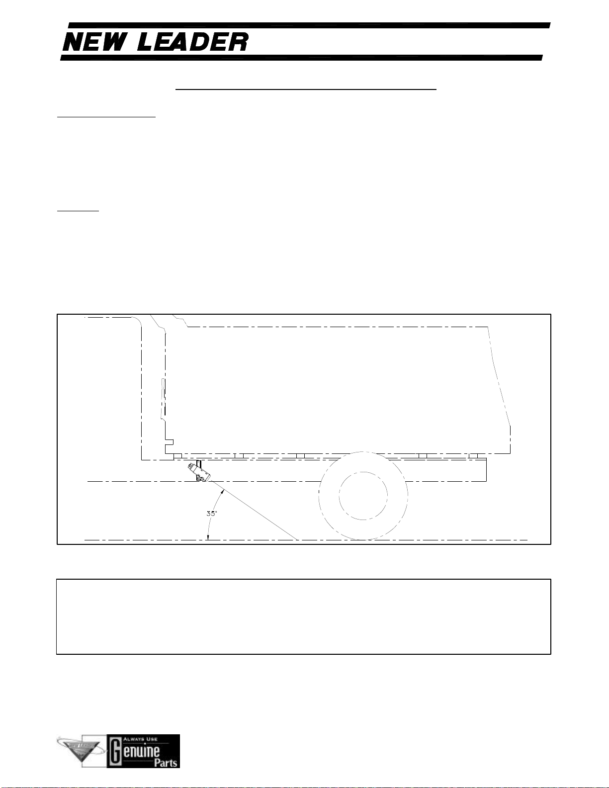
RADAR
The mounting of the radar unit will vary with the type of vehicle. The mounting kit supplied uses an
"L" shaped bracket and mounting plate. There is also a plate mounting bracket drawing that can be used
to fabricate a bolt-on version. Refer to the installation instructions included with the radar for more
information.
The radar should be mounted facing rearward and at a 35°angle horizontally. (Figure 2)
Figure 2 - Radar Mounting Angle
If at anytime an arc welder is used on the vehicle or anything connected to the
vehicle, be sure to connect the welders ground directly to one of the two items
being welded. Disconnect power cable from the Mark series control box! Failure
to do so can result in damage to components on both the vehicle and spreader in
which case the warranty will be null and void by manufacturer of same.
IMPORTANT!

Please Give Part No., Description and Unit Serial No.
HIGHWAY EQUIPMENT COMPANY
11
89008-A
Page Rev. A
CONSOLE OVERVIEW
KEYPAD AND DISPLAY
The first step in operating the Mark V is to understand the function of the keys and how they relate to
the console display. There are two toggle switches and four groups of unlabeled white push keys. The
push key groups are defined as Arrow keys, Display Selection keys, Menu key, and Menu Selection
keys. Display Selection key and Menu key labels appear on the display adjacent to these keys.
A summary of key functions follows. Also, a Quick Reference sheet is included with the Mark V and is
a handy tool.
Figure 3
Power Switch: Selects power ON ( | ) and OFF (O) for the console.
Conveyor Switch: Turns the main conveyor ON (green) and OFF (red).
Menu Key : Used to exit setup screen or advance menu display.
Menu Selection Keys: Activates the menu or picks the command displayed directly above the key. The
left and right arrow keys display other menu choices when arrows are displayed.
Display Selection Keys: Selects the display line to the left of the key and displays a new menu selection
at the lower edge of the display.
Arrow Keys: Changes value of a selected display line when up and down arrow symbols are present.
Used to navigate setup screens and change values of highlighted areas.
Display
Selection Keys
Menu Selection
Keys
Menu Key
Power
Switch
Conveyor
On/Off
Switch
“DG” appears here when a
DGPS-5000 is connected
and the signal is good.
Arrow
Keys

Please Give Part No., Description and Unit Serial No.
HIGHWAY EQUIPMENT COMPANY
12
89008-A
Page Rev. A
CONSOLE OVERVIEW
Figure 4 is an example of the main screen of the Mark V that is displayed on power up. The display
shows four typical on-the-go parameters. A menu selection area is along the lower edge of the screen.
The menu selection area also displays current information about an active job or machine condition.
The Quick Reference sheet included with the Mark V shows an overview of different screens.
Figure 4
MAIN SCREEN DISPLAY
To change the display items on the start up screen, press the Display Selection key to the right of the
display line you wish to change. A box appears around the display line and four possible display items
appear at the bottom of the screen in the menu selection area. Pressing the Menu Selection Arrow keys
scroll the menu to display new choices.
To select a new display item, press the Menu Selection Key below the item you want to view. This will
replace the previous display line with the one just chosen. You can change all four display lines to the
information you want to view and arrange them in any order.
These arrows indicate there are more display items to
view. Press Menu Selection Arrow keys to view
additional display items.
This selection box indicates you can choose a
different display item for the line. Press Display
Selection key to right of any display line to
change the type of information displayed.
Four
display
lines
display
unique
information
This Up/Down Arrow symbol
indicates pressing the Up or
Down Arrow keys will change
the displayed value. Press
Display Selection key to right
of line to display arrow symbol.
The displayed value can only be
changed for “Rate,” “Spin.
Speed” or “Lightbar Pass#.”
Please Give Part No., Description and Unit Serial No.
HIGHWAY EQUIPMENT COMPANY
13
89008-A
Page Rev. A
CONSOLE OVERVIEW CONTINUED
The choices of the display lines include:
Rate - Displays application rate. Up/down arrows at the right of the display line indicate the rate can be
changed. Select the line and use the Arrow keys to change the rate.
Ground Speed – Displays truck speed using a radar or GPS signal. Also displays selected manual
speed.
Spinner Speed – Displays actual spinner speed. Up/down arrows at the right of the display line indicate
the spinner speed can be changed. Select the line and use the Arrow keys to change the speed. The
target rate for the job setting is displayed at the left. Note: Changing the spinner speed with the Mark
V console requires an optional PWM spinner valve.
Total Applied – Displays total amount of material applied. Reset to zero using the Menu Selection key
under Clear.
Area Applied – Displays total area applied. Reset to zero using the Menu Selection key under Clear.
Conveyor RPM – Displays the conveyor revolutions per minute.
Lightbar Pass# - Displays pass number and direction from A-B line when optional DGPS is connected.
Line can be selected to change the pass number or direction using the Menu Selection Arrow keys. See
your DGPS & Lightbar Manual for further information. [Note: Do not display this item if a DGPS
system is not connected.]
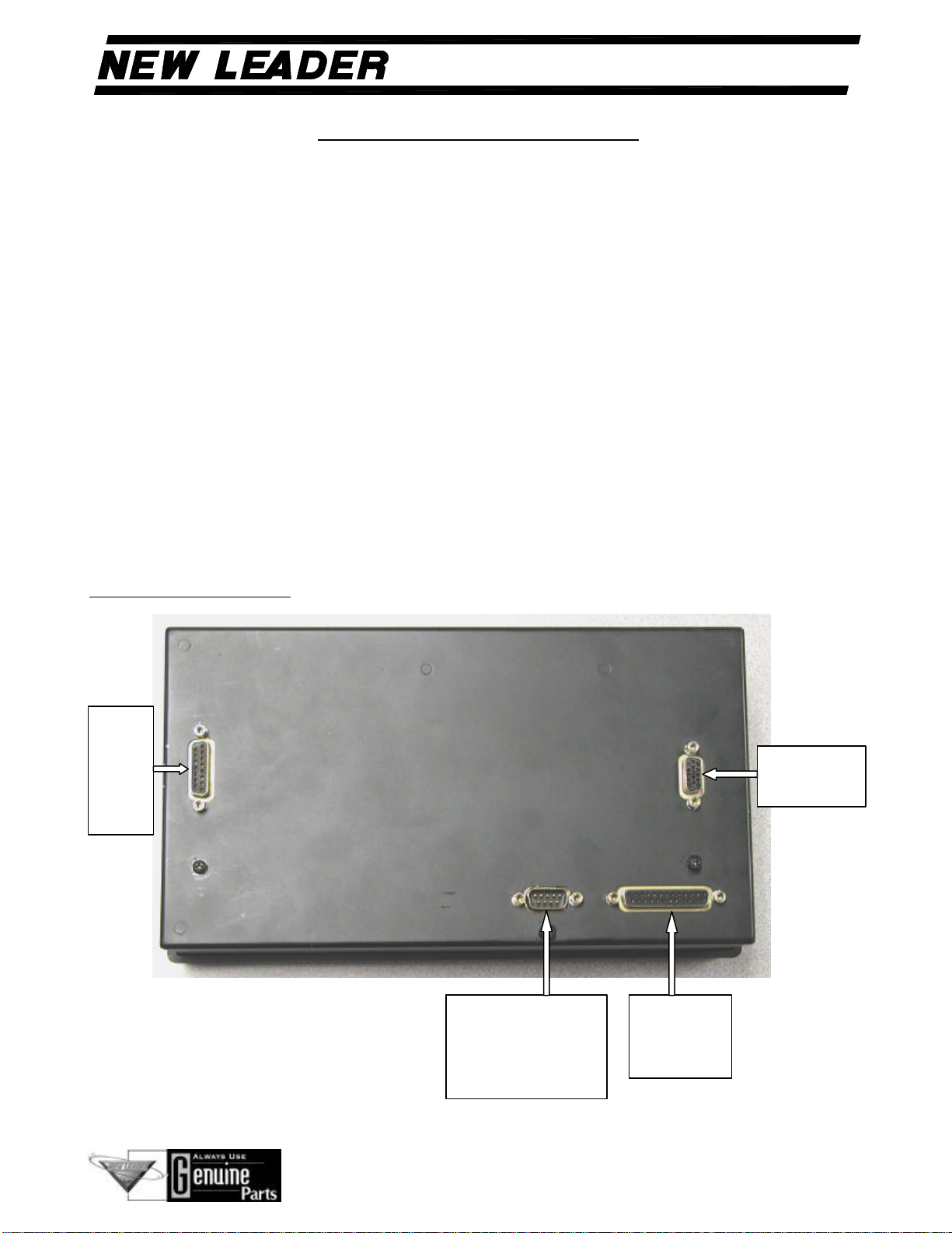
CABLE CONNECTIONS:
Figure 5
Main Port –
Power and
sensors
Port 1 – Connects
to remote device or
to computer for
firmware upgrade.
Aux 2
Port –
Valve
control
signals
Aux 1 Port –
DGPS5000

Please Give Part No., Description and Unit Serial No.
HIGHWAY EQUIPMENT COMPANY
14
89008-A
Page Rev. A
CALIBRATION AND MACHINE SETTINGS
Prior to running any job and spreading material, the Mark V needs to be configured and calibrated to
match the spreader you are using. The console can also be set up to match the preferences of the user.
Any optional GPS must also be configured – see your DGPS & Lightbar manual for more information.
To begin the configuration of your Mark V, start from the main screen and press the Menu Selection
Key directly under SETUP. The screen changes to the Setup Options display. The menu selection area
displays the choices of Machine settings, Cal radar, Console, Diagnostic, and GPS. The right and left
Menu Selection Arrow keys indicate addition selections. Each setup area is entered by pressing the
adjacent Menu Selection Key.
The unit does not have to be installed in the vehicle to make machine settings, console settings, or to
view system diagnostics. An optional power supply is available to operate the unit from your home,
office, or shop.
Machine Settings
From the main screen, press the SETUP key. Press the MACHINE SETTINGS key. The screen shown
in Figure 6 appears.
MACHINE SETTINGS
Spinner valve type BRAND 55 GPM
Theoretical (CFR) 0.256 cu.ft/rev
Ground speed sensor RADAR
Manual speed 10.0 mph
Conveyor switch INTERNAL
Maximum conveyor rpm 50 rpm
Spinner pulses/rev 4
EDIT EXIT
Figure 6

Please Give Part No., Description and Unit Serial No.
HIGHWAY EQUIPMENT COMPANY
15
89008-A
Page Rev. A
CALIBRATION AND MACHINE SETTINGS CONTINUED
To change the settings shown on this screen…
a) Use the Up or Down Arrow Key to highlight a setting.
b) Press the EDIT key. The value will be highlighted.
c) Press the Up or Down Arrow key to change the value. [Note: Conveyor rate, Manual speed,
Maximum conveyor rpm and Spinner pulses/rev values can be set one digit at a time. Press the
Left or Right Arrow key to move a single cursor to the digit to change. Press the Up or Down
Arrow key to set the digit to the desired value. Move the cursor to the right or left and set all
digits to the correct value.]
d) Press the ACCEPT key to accept the new value for the setting. If you decide to keep the old
setting press the CANCEL key
Press the EXIT key to return to the Setup Options screen. Press the Menu Key to return to
the main screen.

Please Give Part No., Description and Unit Serial No.
HIGHWAY EQUIPMENT COMPANY
16
89008-A
Page Rev. A
CALIBRATION AND MACHINE SETTINGS CONTINUED
Machine Setting Details
Spinner Valve Type –
Set to BRAND 55 GPM if you have a L3020G4 bed equipped with an optional PWM spinner
control valve.
Set to BRAND 30 GPM if you have a L2020G4 bed equipped with an optional PWM spinner
control valve.
Set to MANUAL if your bed’s spinner control valve is adjusted with a mechanical lever on the
valve body.
Theoretical CFR
This CFR is the theoretical volume of product dispensed for each revolution of the conveyor shaft with
a gate setting of one inch. The units of measure are cubic feet per revolution per inch of gate opening
(metric units are cubic centimeters per revolution per centimeter of gate opening).
Refer to the tables below for the initial setting. This setting becomes the default value for the CFR in
each job. [Note: Every machine will have a slightly different performance and every product will have
a slightly different flow characteristic. Fine-tuning to a Calibrated CFR is done under JOB SETTING.
Please refer to the procedure described in that section of the manual.]
Theoretical Conveyor Rate Values
Conveyor Rate Conveyor Type Model
.192 cu. ft/rev Chain & BOC L2020G4
.237 cu. ft/rev Belt L2020G4
.256 cu. ft/rev Chain & BOC L3020G4
.305 cu. ft/rev Chain & BOC L7020
.361 cu. ft/rev Chain L7000
Theoretical Conveyor Rate Values (metric)
Conveyor Rate Conveyor Type Model
2140 cu. cm/rev Chain & BOC L2020G4
2641 cu. cm/rev Belt L2020G4
2853 cu. cm/rev Chain & BOC L3020G4
3399 cu. cm/rev Chain & BOC L7020
4023 cu. cm/rev Chain L7000

Please Give Part No., Description and Unit Serial No.
HIGHWAY EQUIPMENT COMPANY
17
89008-A
Page Rev. A
CALIBRATION AND MACHINE SETTINGS CONTINUED
Ground Speed Sensor
Set to RADAR to use a Radar Gun as the source of ground speed.
Set to GPS to use the New Leader DGPS-5000 as the source of ground speed.
Set to MANUAL to use the manual speed setting as the source of ground speed.
If you choose the GPS setting and the differential signal is lost, ground speed from the DGPS-5000 will
go to zero. However, if a radar gun is detected, the Mark V will automatically switch to the radar
before ground speed goes to zero.
The Manual setting can be used when you cannot get ground speed from a radar gun or the DGPS-5000.
During application, you must hold your travel speed the same as the manual speed setting or the rate
applied will be incorrect. New Leader recommends using the manual setting for emergency use only.
In Manual mode, the application accuracy depends on the ability of the operator to drive at the
programmed manual speed.
The Manual setting is also used to empty leftover product from a stationary vehicle or to fine-tune the
CFR.
Manual Speed
Set to desired ground speed for manual operation. When the above Ground Speed Sensor setting is
“Manual,” ground speed is always equal to this setting.
Conveyor Switch
Either the console switch or an optional remote switch can be used to turn on/off the conveyor. The
default setting is “Internal.”
The internal conveyor switch is on the bottom right of the front of the Mark V. Put it in the up position
to turn the conveyor on (Green). Put it in the down position to turn the conveyor off (Red).
Set to INTERNAL to use the switch on the bottom-right of the Mark V front panel to turn the
conveyor on and off.
Set to REMOTE to use an optional remote switch to turn the conveyor on and off.

Please Give Part No., Description and Unit Serial No.
HIGHWAY EQUIPMENT COMPANY
18
89008-A
Page Rev. A
CALIBRATION AND MACHINE SETTINGS CONTINUED
Maximum conveyor rpm
Set to the maximum allowed conveyor RPM. If the vehicle speed is too fast for the programmed
application rate and the conveyor rpm would need to exceed this setting, the Mark V will beep and flash
“Maximum Conveyor RPM, Slow Down”. [Note: The actual conveyor rpm will not exceed this
setting. If the warning to slow down is ignored, the rate applied will be incorrect.]
Set to 50 for an L3020G4.
Set to 40 for an L2020G4.
Spinner pulses/rev
Set to the number of pulses generated by the spinner speed sensor per revolution of the spinner disk.
Set equal to number of fins on the disk.
If a spinner sensor is not active, set to zero. This disables any spinner speed alarm that would be
generated when the spinner speed does not match the job setting.
Press the EXIT key to return to the Setup Options screen. Press the Menu Key to return to
the main screen.
Table of contents
Popular Controllers manuals by other brands


Enovation Controls
Enovation Controls Murphy EMS PRO LITE Installation and operation manual

Bard
Bard MV4000 SERIES Installation & parts manual

GGM
GGM GUB Series manual

RKC INSTRUMENT
RKC INSTRUMENT CB103 INITIAL SETTING MANUAL

Smartrise
Smartrise HYDRO:EVOLVED Startup guide

Carlisle
Carlisle MS Elite 461959 B Series Service manual


