manuals.online logo
Brands
  1. Home
  2. •
  3. Brands
  4. •
  5. HIK VISION
  6. •
  7. Security Camera
  8. •
  9. HIK VISION DS-2CE11D0T-PIRL User manual

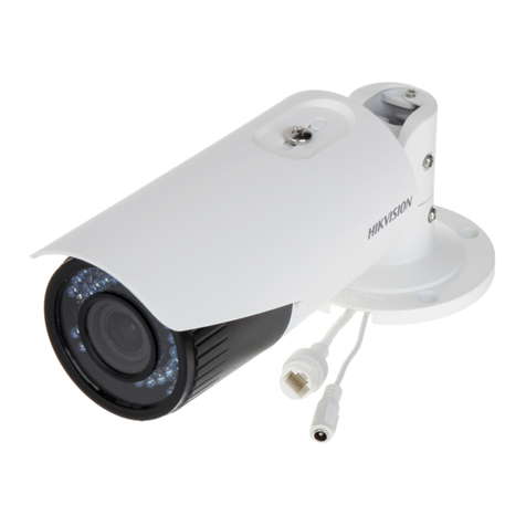
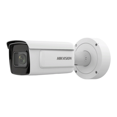
HIK VISION DS-2CE11D0T-PIRL User manual

UM DS-2CE11D0T-PIRL 072718NA
TurboHD
DS-2CE11D0T-PIRL
Bullet Camera
U er Manual
Thank you for purcha ing our product. If there are any que tion or reque t , plea e
contact the dealer.
Thi manual may contain everal technical incorrect place or printing error , and the
content i ubject to change without notice. The update will be added to the new
ver ion of thi manual. We will readily improve or update the product or procedure
de cribed in the manual.
1Regulatory Information
FCC Information
Plea e take attention that change or modification not expre ly approved by the
party re pon ible for compliance could void the u er’ authority to operate the
equipment.
FCC Compliance: Thi equipment ha been te ted and found to comply with the limit
for a Cla A digital device, pur uant to part 15 of the FCC Rule . The e limit are
de igned to provide rea onable protection again t harmful interference when the
equipment i operated in a commercial environment. Thi equipment generate , u e ,
and can radiate radio frequency energy and, if not in talled and u ed in accordance
with the in truction manual, may cau e harmful interference to radio
communication . Operation of thi equipment in a re idential area i likely to cau e
harmful interference in which ca e the u er will be required to correct the
interference at hi own expen e.
FCC Conditions
Thi device complie with part 15 of the FCC Rule . Operation i ubject to the
following two condition :
1. Thi device may not cau e harmful interference.
2. Thi device mu t accept any interference received, including interference that may
cau e unde ired operation.
EU Conformity Statement
Thi product and, if applicable, the upplied acce orie too are marked with
“CE” and comply therefore with the applicable harmonized European
tandard li ted under the Low Voltage Directive 2014/35/EU, the EMC
Directive 2014/30/EU, the RoHS Directive 2011/65/EU.
2012/19/EU ( EEE Directive): Product marked with thi ymbol cannot be
di po ed of a un orted municipal wa te in the European Union. For proper
recycling, return thi product to your local upplier upon the purcha e of
equivalent new equipment, or di po e of it at de ignated collection point .
For more information ee: www.recyclethi .info.
2006/66/EC (Battery Directive): Thi product contain a battery that cannot be
di po ed of a un orted municipal wa te in the European Union. See the
product documentation for pecific battery information. The battery i
marked with thi ymbol, which may include lettering to indicate cadmium
(Cd), lead (Pb), or mercury (Hg). For proper recycling, return the battery to
your upplier or to a de ignated collection point. For more information ee:
www.recyclethi .info.
Industry Canada ICES-003 Compliance
Thi device meet the CAN ICES-3 (A)/NMB-3(A) tandard requirement .
arning
Thi i a cla A product. In a dome tic environment thi product may cau e radio
interference, in which ca e the u er may be required to take adequate mea ure .
Safety Instruction
The e in truction are intended to en ure that u er can u e the product correctly to
avoid danger or property lo .
The precaution mea ure i divided into “Warning ” and “Caution .”
arnings: Seriou injury or death may occur if any of the warning are neglected.
Cautions: Injury or equipment damage may occur if any of the caution are neglected.
All manuals and user guides at all-guides.com
all-guides.com
UM DS-2CE11D0T-PIRL 072718NA
arnings
Follow
the e afeguard to
prevent eriou injury or death.
Cautions
Follow the e
precaution to
prevent potential injury or material
damage.
arnings
•
In the u e of the device, you mu t be in trict compliance with the electrical afety
regulation of the nation and region.

•
Input voltage hould meet both the SELV (Safety Extra Low Voltage) and the Limited
Power Source with 12 VDC according to the IEC60950-1 tandard. Refer to technical
pecification for detailed information.

•
Do not connect multiple device to one power adapter to avoid over-heating or a
fire hazard cau ed by overload.

•
Make ure that the plug i firmly connected to the power ocket.

•
Make ure that the device i firmly fixed if wall mounting or ceiling mounting i u ed.

•
If moke, odor, or noi e ri e from the device, turn off the power at once and unplug
the power cord, and then contact the ervice center.

•
Never attempt to have the camera di a embled by non-profe ional per onnel.

Cautions
•
Do not drop the camera or ubject it to phy ical hock.

•
Do not touch en or module with finger .

•
Do not place the camera in extremely hot, cold (the operating temperature hall be
-40° to 60° C), du ty or damp location , and do not expo e it to high
electromagnetic radiation.

•
If cleaning i nece ary, u e clean cloth with a bit of ethanol and wipe it gently.

•
Do not aim the camera at the un or extra bright place .
•
The en or may be burned out by a la er beam, o if any la er equipment i in u e,
make ure that the en or urface i not expo ed to the la er beam.
•
Do not expo e device to high electromagnetic radiation or extremely hot, cold,
du ty, or damp environment.

•
To avoid heat accumulation, good ventilation i required for the operating
environment.

•
Keep the camera away from liquid while in u e for non-waterproof device.

•
While in delivery, the camera hall be packed in it original packing or packing of the
ame texture.

Mark Description
Mark
De cription
DC Voltage
2Introduction
2.1 Product Features
The main feature are a follow :
•
High performance CMOS en or

•
IR cut filter with auto witch

•
OSD menu with configurable parameter

•
Auto white balance

•
Internal ynchronization

•
SMART IR mode

•
Vi ible alarm

•
PIR detection

•
3-axi adju tment

2.2 Camera Overview
Figure 1, Camera Overview
All manuals and user guides at all-guides.com
UM DS-2CE11D0T-PIRL 072718NA
3Installation
Before you start
•
Make ure that the device in the package i in good condition and all the a embly
part are included.

•
Make ure that all the related equipment i powered off during the in tallation.

•
Check the pecification of the product for the in tallation environment.

•
Check whether the power upply matche your power output to avoid damage.

•
Make ure the wall i trong enough to with tand three time the weight of the
camera and the mount.

•
If the wall i concrete, in ert expan ion bolt before in talling the camera. If the wall
i wood, u e elf-tapping crew to ecure the camera.

•
If the product doe not function properly, contact your dealer or the neare t ervice
center. Do NOT di a emble the camera for repair or maintenance your elf.

3.1 Camera Installation
3.1.1 Ceiling/ all Mounting without Junction Box
Steps:
1. Pa te the drill template ( upplied) where you want to in tall the camera.
2. Drill the crew hole and the cable hole (optional) in the ceiling/wall according to
the drill template.
Figure 2, Drill Template
Note:
Drill a cable hole if u ing the ceiling outlet to route the cable.
Figure 3, Fix the Camera to the Ceiling
3. Attach the bracket to the ceiling/wall, and ecure the camera with upplied crew .
Note:
The upplied crew package contain elf-tapping crew and expan ion bolt .

For cement wall/ceiling, expan ion bolt are required to fix the camera. For wood
wall/ceiling, elf-tapping crew are required.

Route the cable through the cable hole or ide opening.
4. Connect the corre ponding power cord and video cable.
5. Power on the camera to check if the image on the monitor i at an optimum angle.
If not, adju t the camera according to the figure below to get an optimum angle.
Figure 4, 3-Axi Adju tment
1). Loo en the P crew to adju t the pan po ition [0° to 360°]. Tighten the crew
after completing the adju tment.
All manuals and user guides at all-guides.com
UM DS-2CE11D0T-PIRL 072718NA
2). Loo en the T crew to adju t the tilt po ition [0° to 180°]. Tighten the crew
after completing the adju tment.
3). Loo en the R crew and rotate the camera [0° to 360°]. Tighten the crew after
completing the adju tment.
3.1.2 Ceiling/ all Mounting with Junction Box
Before you start:
You need to purcha e a junction box eparately.
Steps:
1. Pa te the drill template on the ceiling/wall.
2. Drill crew hole and the cable hole in the ceiling/wall according to the drill
template hole .
Figure 5, Junction Box Drill Template
3. Take apart the junction box, and align the bullet camera crew hole with tho e on
the junction box cover.
4. Fix the camera on the junction box cover with upplied crew .
Figure 6, Fix Camera to the Junction Box Cover
5. Attach the junction box body to the ceiling/wall by aligning the crew hole of the
junction box.
6. Secure the junction box’ body with upplied crew on the ceiling/wall.
Figure 7, Fix Junction Box to Wall/Ceiling
7. Route the cable through the bottom cable hole or the ide cable hole of the
junction box.
Figure 8, Re-affix Junction Box Cover to it Body
8. Combine the junction box cover with it body.
9. Repeat tep 5 and 6 of Ceiling/Wall Mounting without Junction Box to complete
the in tallation.
All manuals and user guides at all-guides.com
UM DS-2CE11D0T-PIRL 072718NA
4Menu Description
Purpose:
Call the menu by clicking button on the PTZ Control interface, or call the pre et
no.95.
Steps:
1. Connect the camera to the TVI DVR, and the monitor.
Figure 9, Connection
2. Power on the analog camera, TVI DVR, and the monitor to view the image on the
monitor.
3. Click PTZ Control to enter the PTZ Control interface.
4. Call the camera menu by clicking the button or call pre et no. 95.
5. Click the direction arrow to control the camera.
1). Click up/down direction button to elect the item.
2). Click Iris+ to confirm the election.
3). Click left/right direction button to adju t the value of the elected item.
VIDEO FORMAT
You can et the video format to 2 MP @ 25 fp or 2 MP @ 30 fp .
LANGUAGE
Support Engli h and Chine e.
Figure 10, Main Menu Overview
All manuals and user guides at all-guides.com
UM DS-2CE11D0T-PIRL 072718NA
4.1 EXPOSURE
EXPOSURE MODE
You can et the EXPOSURE MODE a GLOBAL, BLC, or D DR.
•
GLOBAL



GLOBAL refer to the normal expo ure mode which adju t lighting di tribution,
variation , and non- tandard proce ing.
•
BLC (Backlight Compensation)



BLC (Backlight Compen ation) compen ate light to the object in the front to make
it clear, but thi may cau e overexpo ure of the background where light i trong.
•
D DR (Digital ide Dynamic Range)



Digital wide dynamic range help the camera provide clear image even under
backlight circum tance . WDR balance the brightne level of the whole image and
provide clear image with detail .
AGC (Auto Gain Control)
Optimize the clarity of the image in poor light condition . The AGC level can be et to
HIGH, MEDIUM, or LO . Select OFF to di able the AGC function.
Note:
The noi e will be amplified when AGC i on.
DAY/NIGHT
COLOR, B& (Black hite), and AUTO are electable for DAY/NIGHT witche .
•
COLOR
The image i in color in day mode all the time.
•
B/
The image i black and white all the time (it i better to turn the IR LIGHT on in poor
light condition ).
•
AUTO
You can turn on/off the IR LIGHT and et the SMART IR value in thi menu.
Figure 11, DAY/NIGHT
˗
IR LIGHT



You can turn on/off the infrared to meet different requirement .
˗
SMART IR



The Smart IR function adju t the light to it mo t uitable inten ity and prevent
the image from overexpo ure. The SMART IR value can be adju ted from 0 to 3.
The greater the value, the more obviou the effect .
˗
D-N THRESHOLD (Day to Night Threshold)



Day to Night Thre hold control the en itivity of witching the day mode to
night mode. You can et the value from 1 to 9. The larger the value, the more
en itive the camera.
˗
N-D THRESHOLD (Night to Day Threshold)



Night to Day Thre hold control the en itivity of witching the night mode to
day mode. You can et the value from 1 to 9. The larger the value, the more
en itive the camera.
4.2 VIDEO SETTINGS
Move the cur or to VIDEO SETTINGS and click Iris+ to enter the ubmenu. IMAGE
MODE, WHITE BALANCE, CONTRAST, SHARPNESS, COLOR GAIN, 3 DNR, and MIRROR
are adju table.
Figure 12, VIDEO SETTINGS
All manuals and user guides at all-guides.com
all-guides.com
UM DS-2CE11D0T-PIRL 072718NA
IMAGE MODE
IMAGE MODE adju t the image aturation, and you can et it a STD (Standard) or
HIGH-SAT (High Saturation).
HITE BALANCE
White balance, the white rendition function of the camera, adju t the color
temperature according to the environment. It can remove unreali tic color ca t in the
image. You can et B mode to AUTO or MANUAL.
•
AUTO



Under AUTO mode, white balance adju t automatically according to the cene
illumination color temperature.
•
MANUAL



You can et the R GAIN/B GAIN value from 1 to 255 to adju t the hade of
red/blue color of the image.
Figure 13, MWB MODE
BRIGHTNESS
Brightne refer to the brightne of the image. You can et the brightne value from
1 to 9 to darken or brighten the image. The greaterr the value, the brighter the image.
CONTRAST
Thi feature enhance the difference in color and light between part of an image. You
can et the CONTRAST value from 1 to 9.
SHARPNESS
Sharpne determine the amount of detail the imaging y tem can reproduce. You
can et the SHARPNESS value from 1 to 9.
SATURATION
Adju t thi feature to change the color aturation. The value range from 1 to 9.
DNR (Digital Noise Reduction)
The DNR function can decrea e the noi e effect, e pecially when capturing moving
image in poor light condition , to deliver a more accurate and harper image. You can
et the DNR value from 1 to 9.
MIRROR
OFF, H, V, and HV are electable for mirror
•
OFF: The mirror function i di abled
•
H: The image flip 180° horizontally
•
V: The image flip 180° vertically
•
HV: The image flip 180° both horizontally and vertically
4.3 FUNCTIONS
HITE LIGHT
The embedded white light ource can function a a vi ible alarm.
In HITE LIGHT mode, you can et mode to ALARM or OFF.
When you et HITE LIGHT to ALARM, you can et the TRIGGER MODE and the
ALARM MODE parameter to meet your need .
TRIGGER MODE
•
DVR



Set the TRIGGER MODE to DVR. In thi way, the alarm ignal i ent from the DVR,
and the camera work a the alarm detector in the proce . Be ide , the alarm type
only upported by the DVR can al o trigger the vi ible alarm in the camera.
•
CAMERA



Set the TRIGGER MODE to CAMERA, the embedded PIR module end the alarm
ignal to the vi ible alarm in the camera, when PIR module detect the alarm
ource.
ALARM
You can et the ALARM MODE a SOLID or FLASHING.
All manuals and user guides at all-guides.com
UM DS-2CE11D0T-PIRL 072718NA
Figure 14, ALARM MODE
•
SOLID



Set the ALARM MODE to SOLID. In thi way, the white light ource turn on when
the PIR module receive the alarm ignal.
In TIME SETTING you can et the time a 5 , 10 , 15 , 30 , or 60 , which mean
that the olid mode tay for the et time when the camera receive one alarm
ignal.
Note:
The olid mode will tay for another et time when a econd alarm ignal i received,
and the re t can be done in the ame way.
•
FLASHING



Set the ALARM MODE to FLASHING. In thi way, the white light ource fla he
when the PIR module receive the alarm ignal.
TRIGGER MODE
•
DVR



Set the TRIGGER MODE to DVR. In thi way, the alarm ignal i ent from the DVR,
and the camera work a the alarm detector in the proce . Be ide , the alarm type
only upported by the DVR can al o trigger the vi ible alarm in the camera.
•
CAMERA



Set the TRIGGER MODE to CAMERA, the embedded PIR module end the alarm
ignal to the vi ible alarm in the camera, when PIR module detected the alarm
ource.
OFF
Select OFF to di able thi function.
PIR LEVEL
Adju t the en itivity of the PIR module, and the greater the value, the more en itive
the PIR module.
FACTORY DEFAULT
Re et all the etting to the factory default.
EXIT
Move the cur or to EXIT and click Iris+ to exit the menu.
SAVE & EXIT
Move the cur or to SAVE & EXIT and click Iris+ to ave the etting and exit the menu.
All manuals and user guides at all-guides.com

Other manuals for DS-2CE11D0T-PIRL

2

This manual suits for next models

1

Other HIK VISION Security Camera manuals

HIK VISION D7T Series User manual

HIK VISION

HIK VISION D7T Series User manual

HIK VISION DS-2CE17U8T-IT User manual

HIK VISION

HIK VISION DS-2CE17U8T-IT User manual

HIK VISION DS-2CE19H8T-IT3ZF User manual

HIK VISION

HIK VISION DS-2CE19H8T-IT3ZF User manual

HIK VISION DS-2XE6126FWD-HS User manual

HIK VISION

HIK VISION DS-2XE6126FWD-HS User manual

HIK VISION TURBO HD DF7T Series User manual

HIK VISION

HIK VISION TURBO HD DF7T Series User manual

HIK VISION DS-2DF8836IX-AEL User manual

HIK VISION

HIK VISION DS-2DF8836IX-AEL User manual

HIK VISION iDS-2CD8A46G0-IZHS User manual

HIK VISION

HIK VISION iDS-2CD8A46G0-IZHS User manual

HIK VISION NK44W1H-1T User manual

HIK VISION

HIK VISION NK44W1H-1T User manual

HIK VISION DS-2CD2045FWD-I-6MM User manual

HIK VISION

HIK VISION DS-2CD2045FWD-I-6MM User manual

HIK VISION DS-2CD2412F-I Operator's manual

HIK VISION

HIK VISION DS-2CD2412F-I Operator's manual

HIK VISION DS-2CD6D54G1-IZS User manual

HIK VISION

HIK VISION DS-2CD6D54G1-IZS User manual

HIK VISION DS-2CD883F-E series User guide

HIK VISION

HIK VISION DS-2CD883F-E series User guide

HIK VISION TurboHD H0T Series User manual

HIK VISION

HIK VISION TurboHD H0T Series User manual

HIK VISION NSC-4A220-PTZIR User manual

HIK VISION

HIK VISION NSC-4A220-PTZIR User manual

HIK VISION DS-2CD7133-E User manual

HIK VISION

HIK VISION DS-2CD7133-E User manual

HIK VISION TURBO HD H1T Series User manual

HIK VISION

HIK VISION TURBO HD H1T Series User manual

HIK VISION DS-2TD2667T-15/P User manual

HIK VISION

HIK VISION DS-2TD2667T-15/P User manual

HIK VISION DS-2CD876BF User manual

HIK VISION

HIK VISION DS-2CD876BF User manual

HIK VISION DS-2DF6223-CX User manual

HIK VISION

HIK VISION DS-2DF6223-CX User manual

HIK VISION DS-2TD4166-50/V2 User manual

HIK VISION

HIK VISION DS-2TD4166-50/V2 User manual

HIK VISION DS-2CE56D1T-AVPIR3 User manual

HIK VISION

HIK VISION DS-2CE56D1T-AVPIR3 User manual

HIK VISION iDS-2CD7A G0-IZH Series User manual

HIK VISION

HIK VISION iDS-2CD7A G0-IZH Series User manual

HIK VISION DS-2CE10DFT-F User manual

HIK VISION

HIK VISION DS-2CE10DFT-F User manual

HIK VISION DS-2CD2347G2-LSU Assembly instructions

HIK VISION

HIK VISION DS-2CD2347G2-LSU Assembly instructions

Popular Security Camera manuals by other brands

AJA rovocam Installation & operation guide

AJA

AJA rovocam Installation & operation guide

ZTV Electron ZT-822TN user manual

ZTV Electron

ZTV Electron ZT-822TN user manual

Amcrest IP5M-1176EW-36MM user manual

Amcrest

Amcrest IP5M-1176EW-36MM user manual

Vivotek IP8364-C Quick installation guide

Vivotek

Vivotek IP8364-C Quick installation guide

Axis M30 Series user manual

Axis

Axis M30 Series user manual

Panasonic Super Dynamic III WV-CP480 Brochure & specs

Panasonic

Panasonic Super Dynamic III WV-CP480 Brochure & specs

Philips VCM7178/00T user manual

Philips

Philips VCM7178/00T user manual

JVC TK-C205E A Specifications

JVC

JVC TK-C205E A Specifications

Hitachi KP-FM500WCL Operation manual

Hitachi

Hitachi KP-FM500WCL Operation manual

Innotech EXCA233BNC Series Quick installation guide

Innotech

Innotech EXCA233BNC Series Quick installation guide

Reconyx HYPERFIRE user guide

Reconyx

Reconyx HYPERFIRE user guide

Digital Watchdog B1362TIR650 instruction manual

Digital Watchdog

Digital Watchdog B1362TIR650 instruction manual

Axis P5514 PTZ user manual

Axis

Axis P5514 PTZ user manual

Lumens VC-B30UAB installation guide

Lumens

Lumens VC-B30UAB installation guide

4xem WPTS Specifications

4xem

4xem WPTS Specifications

Zeiss AxioCam ERc 5s user guide

Zeiss

Zeiss AxioCam ERc 5s user guide

Fujitsu CG-301 Series instruction manual

Fujitsu

Fujitsu CG-301 Series instruction manual

Sunell SN-TPC4201KT-F user manual

Sunell

Sunell SN-TPC4201KT-F user manual

manuals.online logo
manuals.online logoBrands
  • About & Mission
  • Contact us
  • Privacy Policy
  • Terms and Conditions

Copyright 2025 Manuals.Online. All Rights Reserved.