manuals.online logo
Brands
  1. Home
  2. •
  3. Brands
  4. •
  5. HIK VISION
  6. •
  7. Security Camera
  8. •
  9. HIK VISION DS-2CE17U8T-IT User manual

HIK VISION DS-2CE17U8T-IT User manual

UM DS-2CE1xU8T-ITx 042618NA 1
• DS-2CE17U8T-IT
• DS-2CE18U8T-IT3
TurboHD
4K Series Bullet Camera
User Manual
Thank you for urchasing our roduct. If there are
any questions or requests, do not hesitate to contact
the dealer.
This manual a lies to the models below:
This manual may contain technical incorrect laces or
rinting errors, and the content is subject to change
without notice. The u dates will be added to the new
version of this manual. We will readily im rove or
u date the roducts or rocedures described in the
manual.
1Preface
1.1 Regulatory nformation
1.1.1 FCC nformation
Please take attention that changes or modification
not ex ressly a roved by the arty res onsible for
com liance could void the user’s authority to o erate
the equi ment.
FCC Compliance: This equi ment has been tested and
found to com ly with the limits for a Class A digital
device, ursuant to art 15 of the FCC Rules. These
limits are designed to rovide reasonable rotection
against harmful interference when the equi ment is
o erated in a commercial environment. This
equi ment generates, uses, and can radiate radio
frequency energy and, if not installed and used in
accordance with the instruction manual, may cause
harmful interference to radio communications.
O eration of this equi ment in a residential area is
likely to cause harmful interference, in which case the
user will be required to correct the interference at his
own ex ense.
Typ
e
Model
Type Camera
DS
-
2CE17U8T
-
IT
Type Camera
DS
-
2CE18U8T
-
IT3
UM DS-2CE1xU8T-ITx 042618NA 2
1.1.2 FCC Conditions
This device com lies with art 15 of the FCC Rules.
O eration is subject to the following two conditions:
1. This device may not cause harmful interference.
2. This device must acce t any interference received,
including interference that may cause undesired
o eration.
1.1.3 EU Conformity Statement
This roduct and, if a licable, the
su lied accessories too are marked with
“CE” and com ly therefore with the
a licable harmonized Euro ean standards
listed under the Low Voltage Directive
2014/35/EU, the EMC Directive
2012/19/EU (WEEE Directive): Products
marked with this symbol cannot be
dis osed of as unsorted munici al waste in
the Euro ean Union. For ro er recycling,
return this roduct to your local su lier
u on the urchase of equivalent new
equi ment, or dis ose of it at designated
collection oints. For more information see:
www.recyclethis.info.
2006/66/EC (Battery Directive): This
roduct contains a battery that cannot be
dis osed of as unsorted munici al waste in
the Euro ean Union. See the roduct
documentation for s ecific battery
information. The battery is marked with this
symbol, which may include lettering to
indicate cadmium (Cd), lead (Pb), or
mercury (Hg). For ro er recycling, return
the battery to your su lier or to a
designated collection oint. For more
information see: www.recyclethis.info.
1.1.4 ndustry Canada CES-003 Compliance
This device meets the CAN ICES-3 (A)/NMB-3(A)
standards requirements.
1.1.5 Safety nstruction
These instructions are intended to ensure that the
user can use the roduct correctly to avoid danger or
ro erty loss.
The recaution measure is divided into “Warnings”
and “Cautions.”
Warnings: Serious injury or death may occur if any of
the warnings are neglected.
Cautions: Injury or equi ment damage may occur if
any of the cautions are neglected.
Warnings
Follow these
safeguards to revent
serious injury or death.
Cautions
Follow these
recautions to revent
otential injury or
material
damage.
UM DS-2CE1xU8T-ITx 042618NA 3
1.1.6
Warnings
•In the use of the device, you must be in strict
com liance with the electrical safety regulations of
the nation and region.
•In ut voltage should meet both the SELV (Safety
Extra Low Voltage) and the Limited Power Source
with 12 VDC according to the IEC60950-1 standard.
Refer to technical s ecifications for detailed
information.
•The camera is owered by the external DC ower
su ly (12 VDC, 1 A) that com lies with the LPS,
and the out ut current of this external DC ower
su ly must be no more than 6 A.
•Do not connect multi le devices to one ower
ada ter to avoid over-heating or a fire hazard
caused by overload.
•Make sure that the lug is firmly connected to the
ower socket.
•Make sure that the device is firmly fixed if wall
mounting or ceiling mounting is ado ted.
•If smoke, odor, or noise rise from the device, turn
off the ower at once and un lug the ower cord,
and then contact the service center.
•Never attem t to disassemble the camera by
un rofessional ersonal.

1.1.7
Cautions
•Do not dro the camera or subject it to hysical
shock.
•Do not touch sensor modules with fingers.
•Do not lace the camera in extremely hot, cold
(the o erating tem erature shall be -40° to 60° C),
dusty or dam locations, and do not ex ose it to
high electromagnetic radiation.
•If cleaning is necessary, use a clean cloth with a bit
of ethanol, and wi e it gently.
•Do not aim the camera at the sun or extra bright
laces.
•The sensor may be burned out by a laser beam, so
when any laser equi ment is in using, make sure
that the sensor surface will not be ex osed to the
laser beam.
•Do not ex ose the device to high electromagnetic
radiation or extremely hot, cold, dusty, or dam
environments.
•To avoid heat accumulation, good ventilation is
required for the o erating environment.
•Kee the camera away from liquid while in use for
non-water roof devices.
•While in delivery, the camera shall be acked in its
original acking, or acking of the same material.

UM DS-2CE1xU8T-ITx 042618NA 4
1.1.8 Mark Description
Table 0-1 Mark Descri tion
Mark
Descri tion
DC Vo
ltage
2ntroduction
2.1 Product Features
The camera is a licable for both indoor and outdoor
conditions. A lication scenarios include roads,
warehouses, underground arking lots, bars, etc..
The main features are as follows:
•8 MP high erformance CMOS sensor
•IR cut filter with auto switch
•OSD menu with configurable arameters
•Auto white balance
•internal synchronization
•SMART IR mode
•3-axis adjustment
2.2 Overview
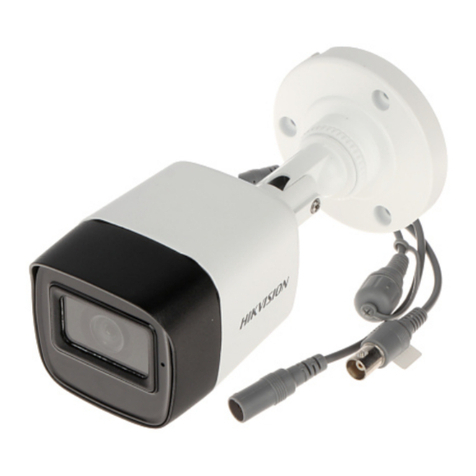
This manual a lies to two ty es of bullet cameras.
The overviews of each ty e are shown in the figures
below.
2.2.1 Overview of Type Camera
Figure 1 Overview of Ty e I Camera
2.1.1
Overview of Type Camera
Figure 2 Overview of Ty e II Camera
3nstallation
Before you start:
•Make sure that the device in the ackage is in good
condition and all the assembly arts are included.

•Make sure that all the related equi ment is
owered off during the installation.

UM DS-2CE1xU8T-ITx 042618NA 5
•Check the s ecification of the roducts for the
installation environment.

•Check whether the ower su ly matches your
ower out ut to avoid the damage.

•Make sure the wall is strong enough to withstand
three times the weight of the camera and the
mount.

•If the wall is cement, insert ex ansion bolts before
installing the camera. If the wall is wooden, use
self-ta ing screws to secure the camera.

•If the roduct does not function ro erly, contact
your dealer or the nearest service center. Do NOT
disassemble the camera for re air or maintenance
by yourself.

3.1 nstallation of Type Camera
3.1.1 Ceiling/Wall Mounting without Junction Box
Steps
:
1. Paste the drill tem late (su lied) where you want
to install the camera.
2. Drill the screw holes and the cable hole (o tional)
in the ceiling/wall according to the drill tem late.
Figure 3 Drill Tem late
Note:
Drill the cable hole when using the ceiling outlet to
route the cable.
3. Attach the bracket to the ceiling/wall and secure
the camera with su lied screws.
Figure 4 Fix the Camera to the Ceiling
UM DS-2CE1xU8T-ITx 042618NA 6
Note:
•The su lied screw ackage contains self-ta ing
screws and ex ansion bolts.

•For cement wall/ceiling, ex ansion bolts are
required to fix the camera. For wooden
wall/ceiling, self-ta ing screws are required.

4. Route the cables through the cable hole or the side
o ening.
5. Connect the corres onding ower cord and video
cable.
6. Power on the camera to check if the image on the
monitor is at an o timum angle. If not, adjust the
camera according to the figure below to get an
o timum angle.
Figure 5 3-axis Adjustment
1). Loosen the P screw to adjust the an osition
[0° to 360°]. Tighten the screw after
com leting the adjustment.
2). Loosen the T screw to adjust the tilt osition
[0° to 180°]. Tighten the screw after
com leting the adjustment.
3). Loosen the R screw and rotate the camera [0°
to 360°]. Tighten the screw after com leting
the adjustment.
3.1.2 Ceiling/Wall Mounting with Junction Box
Before you start:
You need to urchase a junction box se arately.
Steps:
1. Paste the drill tem late on the ceiling/wall.
2. Drill screw holes, and the cable hole (o tional) in
the ceiling/wall according to the holes of the drill
tem late.
UM DS-2CE1xU8T-ITx 042618NA 7
Figure 6 Drill Tem late of Junction Box
Note:
Drill the cable hole when using the ceiling outlet to
route the cable.
3. Take a art the junction box, and align the screw
holes of the bullet camera with those on the
Junction box cover.
4. Fix the camera on the junction box’s cover with
su lied screws.
Figure 7 Fix the Camera on the Junction Box Cover
5. Attach the junction box body to the ceiling/wall by
aligning the screw holes of the junction box.
6. Secure the junction box body with su lied screws
on the ceiling/wall.
Figure 8 Fix the Junction Box to the Wall/Ceiling
UM DS-2CE1xU8T-ITx 042618NA 8
7. Route the cables through the bottom cable hole
(o tional) or the side cable hole of the junction
box.
8. Combine the junction box cover with its body.
Figure 9 Fix the Junction Box Cover Back to its Body
9. Re eat the ste 5 and 6 of 2.1.1 Ceiling/Wall
Mounting without Junction Box to com lete the
installation.
3.2 nstallation of Type Camera
3.2.1 Ceiling/Wall Mounting without Junction Box
Steps:
1. Paste the drill tem late (su lied) to the lace
where you want to install the camera.
2. Drill the screw holes according to the drill tem late
and the cable hole (o tional) on the ceiling/wall.
Figure 10 Drill Tem late
Note:
Drill the cable hole in the center of the drill tem late
when using ceiling outlet to route the cable.
3. Route the cables through the cable hole (o tional)
or the side o ening.
4. Fix the camera to the ceiling with su lied screws.
UM DS-2CE1xU8T-ITx 042618NA 9
Figure 11 Fix the Camera to the Ceiling
Note:
•The su lied screw ackage contains self-ta ing
screws, and ex ansion bolts.

•For cement wall/ceiling, ex ansion bolts are
required to fix the camera. For wooden
wall/ceiling, self-ta ing screws are required.

5. Connect the corres onding ower cord and video
cable.
6. Power on the camera to check if the image on the
monitor is at an o timum angle. If not, adjust the
surveillance angle.
Figure 12 3-Axis Adjustment
1). Loosen the No.1 adjusting screw to adjust the
an osition [0° to 360°]. Tighten the No.1
adjusting screw.
2). Loosen the No.2 adjusting screw to adjust the
tilting osition [0° to180°]. Tighten the No. 2
adjusting screw.
3). Loosen the No.3 adjusting screw to adjust the
rotation osition [0° to 360°]. Tighten the No.3
adjusting screw.
3.2.2 Ceiling/Wall Mounting with Junction Box
Before you start:
You need to urchase a junction box se arately.
Steps:
1. Paste the drill tem late on the ceiling/wall.
2. Drill screw holes and the cable hole (o tional) in
the ceiling/wall according to the holes of the drill
tem late.
UM DS-2CE1xU8T-ITx 042618NA 10
Figure 13 Drill Tem late
Note:
Drill the cable hole, when ado ting ceiling outlet to
route the cable.
3. Take a art the junction box, and align the screw
holes of the bullet camera with those on the
Junction box’s cover.
4. Fix the camera on the junction box cover with
three su lied screws.
Figure 14 Fix the Camera on the Junction Box Cover
5. Secure the junction box’s body with su lied
screws on the ceiling/wall.
Figure 15 Install the Junction Box
UM DS-2CE1xU8T-ITx 042618NA 11
6. Route the cables through the bottom cable hole or
the side cable hole of the junction box.
7. Combine the junction box cover with its body with
su lied screws on the junction box cover.
Figure 16 Combine the Junction Box’s Cover with its
Body
8. Re eat ste 5 and 6 of 2.2.1 Ceiling/Wall Mounting
without Junction Box to com lete the installation.
4Menu Description
Purpose:
Call the menu by clicking button on the PTZ
Control interface, or call reset No.95.
Steps:
1. Connect the camera to the TVI DVR and the
monitor, as shown below.
Figure 17 Connection
2. Power on the analog camera, TVI DVR, and the
monitor to view the image on the monitor.
3. Click PTZ Control to enter the PTZ Control
interface.
4. Call the camera menu by clicking the button, or
call reset No. 95.
UM DS-2CE1xU8T-ITx 042618NA 12
Figure 18 Main Menu Overview
5. Click the direction arrow to control the camera.
1). Click u /down direction button to select the
item.
2). Click Iris + to confirm the selection.
3). Click left/right direction button to adjust the
value of the selected item.
4.1 Video Format
You can set frame rate as 8 MP @ 12.5 f s, 8 MP @
15 f s, 5 MP @ 20 f s, 4 MP @ 25 f s, 4 MP @ 30 f s,
1080 @ 25 f s, or 1080 @ 30 f s.
4.2 Language
Su orts English.
4.3 Settings
4.3.1 Exposure
Ex osure describes the brightness-related
arameters, which can be adjusted by Brightness,
Exposure Mode, AGC, and Slow Shutter.
UM DS-2CE1xU8T-ITx 042618NA 13
Figure 19 Ex osure
•Brightness
Brightness refers to the brightness of the image.
You can set the brightness value from 1 to 10 to
darken or brighten the image. The higher the
value, the brighter the image.
•Exposure Mode
You can set the Exposure Mode as Global, BLC,
HLC, and WDR.
˗
Global



Global refers to the normal ex osure
mode which adjusts lighting distribution,
variations, and non-standard rocessing.
˗BLC (Backlight Compensation)
BLC (Backlight Com ensation)
com ensates light to the object in the
front to make it clear, but this may cause
the over-ex osure of the background
where the light is strong.
˗HLC (High Light Compensation)
HLC (High Light Com ensation) masks
strong light sources that usually flare
across a scene. This makes it ossible to
see the detail of the image that would
normally be hidden.
˗WDR (Wide Dynamic Range)
The wide dynamic range hel s the camera
rovide clear images even under backlight
circumstances. WDR balances the
brightness level of the whole image and
rovides clear images with details.
When WDR is selected as the ex osure
mode, you can set it as low, medium, high,
or off.
•AGC (Automatic Gain Control)
It o timizes the clarity of the image in oor light
conditions. The AGC level can be set as High,
Medium, or Low. Select Off to disable the AGC
function.
UM DS-2CE1xU8T-ITx 042618NA 14
Note:
The noise will be am lified when the AGC is on.
•Slow Shutter
Slow Shutter increases the ex osure time on a
single frame, which makes a camera more
sensitive to light. Therefore, it can roduce images
even under low lux conditions. You can set the
Slow Shutter as Off, x2, x4 under 8 MP @ 15 f s,
or 8 MP @ 12.5 f s mode, and as Off, x2, x4, x6,
x8, or x16 under other modes according to
different light conditions.
4.3.2 WB (White Balance)
White balance, the white rendition function of the
camera, is to adjust the color tem erature according
to the environment. It can remove unrealistic color
casts in the image. You can set WB mode as Auto,
Manual, or Natural.
•Auto
Under Auto mode, white balance is being adjusted
automatically according to the color tem erature
of the scene illumination.
•Manual
Click Iris+ to enter the submenu, you can set the R
Gain/B Gain value from 1 to 255 to adjust the
shades of red/blue color of the image.
Figure 20 White Balance
•Natural
Set the white balance as the Natural mode, when
large art of the monitoring scene is monochrome.
4.3.3 Day Night
Color, BW (Black White), and AUTO are selectable for
DAY and NIGHT switches.
•Color
The image is colored in day mode all the time.
•B/W
The image is black and white all the time, and the
IR light turns on in the oor light conditions.
•Auto
The image switches from color to B/W, or from
B/W to color automatically according to the light
conditions.
UM DS-2CE1xU8T-ITx 042618NA 15
Click Iris+ to enter the submenu, you can turn
on/off the R Light and set the value of Smart R in
this menu.
Figure 21 Day Night
•
R Light



You can turn on/off the IR Light to meet the
requirements of different circumstances.
•
Smart R



The Smart R function is used to adjust the light to
its most suitable intensity, and revent the image
from over ex osure. You can turn on/off this
function.
•
DN Threshold (Day to Night Threshold)



Day to Night Threshold is used to control the
sensitivity of switching the day mode to the night
mode. You can set the value from 1 to 9. The
larger the value is, the more sensitive the camera
is.
•
ND Threshold (Night to Day Threshold)



Night to Day Threshold is used to control the
sensitivity of switching the night mode to the day
mode. You can set the value from 1 to 9. The
larger the value is, the more sensitive the camera
is.
4.3.4 Video Settings
Move the cursor to Video Settings and click Iris+ to
enter the submenu. Contrast, Sharpness, Saturation,
3D DNR, Mirror, and Defog are adjustable.
Figure 22 Video Settings
UM DS-2CE1xU8T-ITx 042618NA 16
•Contrast
This feature enhances the difference in color and
light between arts of an image. You can set the
Contrast value from 1 to 10.
•Sharpness
Shar ness determines the amount of detail an
imaging system can re roduce. You can set the
Sharpness value from 1 to 10.
•Saturation
Adjust this feature to change the saturation of the
color. The value ranges from 1 to 10.
•3D DNR (Digital Noise Reduction)
The 3D DNR function can decrease the noise
effect, es ecially when ca turing moving images in
oor light conditions, and deliver more accurate
and shar image quality. You can set the 3D DNR
value from 1 to 10.
•Mirror
Off, H, V, and HV are selectable for mirror.
Off: The mirror function is disabled. H: The image
fli s 180° horizontally. V: The image fli s 180°
vertically.
HV: The image fli s 180° both horizontally and
vertically.
•Defog
It is used in s ecial environments such as foggy or
rainy weather, or in high illumination conditions, in
which the dynamic range is lower than that in an
ordinary environment and the image a ears hazy.
Enabling the defog function can enhance subtle
details to dis lay clear images.
4.4 Factory Default
Click Iris+ to enter the submenu, and click OK to reset
all the settings to the factory default. Click Cancel to
give u the reset settings.
4.5 Save & Exit
Move the cursor to Save & Exit, and click Iris+ to save
the settings and exit the menu.

Other manuals for DS-2CE17U8T-IT

1

This manual suits for next models

1

Other HIK VISION Security Camera manuals

HIK VISION UD.6L0201B2074A01 User manual

HIK VISION

HIK VISION UD.6L0201B2074A01 User manual

HIK VISION DS-2CE12KF3T-PIRXO User manual

HIK VISION

HIK VISION DS-2CE12KF3T-PIRXO User manual

HIK VISION DS-2CD6D54G1-ZS User manual

HIK VISION

HIK VISION DS-2CD6D54G1-ZS User manual

HIK VISION DS-2DE4582AE User manual

HIK VISION

HIK VISION DS-2DE4582AE User manual

HIK VISION D3T Series User manual

HIK VISION

HIK VISION D3T Series User manual

HIK VISION DS-2TD2667-15/PY User manual

HIK VISION

HIK VISION DS-2TD2667-15/PY User manual

HIK VISION DS-2CD2712F-I User guide

HIK VISION

HIK VISION DS-2CD2712F-I User guide

HIK VISION I0D2400 User manual

HIK VISION

HIK VISION I0D2400 User manual

HIK VISION DS?2CC1102P(N)(?A) User manual

HIK VISION

HIK VISION DS?2CC1102P(N)(?A) User manual

HIK VISION PanoVu PT Series User manual

HIK VISION

HIK VISION PanoVu PT Series User manual

HIK VISION DS-2TD1228T-2/QA User manual

HIK VISION

HIK VISION DS-2TD1228T-2/QA User manual

HIK VISION DS-2CE16H0T-ITE User manual

HIK VISION

HIK VISION DS-2CE16H0T-ITE User manual

HIK VISION TURBO HD DS-2CE5AC5T-AVPIT3Z User manual

HIK VISION

HIK VISION TURBO HD DS-2CE5AC5T-AVPIT3Z User manual

HIK VISION DS-2XE Series User manual

HIK VISION

HIK VISION DS-2XE Series User manual

HIK VISION TURBO HD H0T Series User manual

HIK VISION

HIK VISION TURBO HD H0T Series User manual

HIK VISION DS-MH6171I-A User manual

HIK VISION

HIK VISION DS-MH6171I-A User manual

HIK VISION DS-2TD2636B-15/P User manual

HIK VISION

HIK VISION DS-2TD2636B-15/P User manual

HIK VISION 4 Inch High Speed Dome User manual

HIK VISION

HIK VISION 4 Inch High Speed Dome User manual

HIK VISION PTZ Ultra Series User manual

HIK VISION

HIK VISION PTZ Ultra Series User manual

HIK VISION D8T Series User manual

HIK VISION

HIK VISION D8T Series User manual

HIK VISION DS-2DF5276 Series User manual

HIK VISION

HIK VISION DS-2DF5276 Series User manual

HIK VISION iVMS-4200 User manual

HIK VISION

HIK VISION iVMS-4200 User manual

HIK VISION NETWORK CAMERA User manual

HIK VISION

HIK VISION NETWORK CAMERA User manual

HIK VISION DS?2CC1173P?VF User manual

HIK VISION

HIK VISION DS?2CC1173P?VF User manual

Popular Security Camera manuals by other brands

Vista NCD635CKe installation instructions

Vista

Vista NCD635CKe installation instructions

Genesis HD-DNBC user manual

Genesis

Genesis HD-DNBC user manual

MYDLINK DCS-6100LHV2 Quick installation guide

MYDLINK

MYDLINK DCS-6100LHV2 Quick installation guide

Commax drc-4g user manual

Commax

Commax drc-4g user manual

Digital Watchdog Star-Light Plus DWC-D4583WTIR user manual

Digital Watchdog

Digital Watchdog Star-Light Plus DWC-D4583WTIR user manual

Philips LTC1133/11 installation instructions

Philips

Philips LTC1133/11 installation instructions

Chacon IPCAM FI-04 quick start guide

Chacon

Chacon IPCAM FI-04 quick start guide

JVC VN-C655 instructions

JVC

JVC VN-C655 instructions

Vivotek fd8371v user manual

Vivotek

Vivotek fd8371v user manual

Clover HDC560 install guide

Clover

Clover HDC560 install guide

Moog Videolarm QView QRHPC2-50NA instructions

Moog Videolarm

Moog Videolarm QView QRHPC2-50NA instructions

VADDIO RoboSHOT 12 Series Complete manual

VADDIO

VADDIO RoboSHOT 12 Series Complete manual

Vitek VTC-C960DS Guide

Vitek

Vitek VTC-C960DS Guide

Axis M2025-LE user manual

Axis

Axis M2025-LE user manual

GE Security UVD-XP3DNR(-P) Installation sheet

GE Security

GE Security UVD-XP3DNR(-P) Installation sheet

RS SCC 541H instruction manual

RS

RS SCC 541H instruction manual

Riva RC3502HD-5311 Quick installation guide

Riva

Riva RC3502HD-5311 Quick installation guide

Honeywell HDZ20HDX Specifications

Honeywell

Honeywell HDZ20HDX Specifications

manuals.online logo
manuals.online logoBrands
  • About & Mission
  • Contact us
  • Privacy Policy
  • Terms and Conditions

Copyright 2025 Manuals.Online. All Rights Reserved.