Hillphoenix JNRBHSA Quick start guide

JNRBHSA
JNRZHSA
P112746E
V.1 R.04
08/19
REACH-IN SELF-CONTAINED MERCHANDISER
INSTALLATION & OPERATIONS MANUAL
General Information ............................................... 6
Installation & Trim Out .....................................7-17
Connections & Piping ..........................................18
Pre-Power Checklist ............................................19
Airflow & Case Temperature ................................20
Fans & Case Cleaning .........................................21
Parts Ordering ......................................................22
Appendices ...........................................................23
Table of Contents
To ensure proper functionality and optimum performance, it is STRONGLY recommended that Hillphoenix specialty cases be installed/serviced by qualified tech-
nicians who have experience working with commercial refrigerated display merchandisers and storage cabinets. For a list of Hillphoenix-authorized installation/
service contractors, please visit our website at www.hillphoenix.com.

ii

iii
LIABILITY NOTICE
For Cases with Shelf Lighting Systems
Hillphoenix does NOT design any of its shelf lighting systems or any of its display cases with shelf lighting systems for direct or
indirect exposure to water or other liquids. The use of a misting system or water hose on a display case with a shelf lighting sys-
tem, resulting in the direct or indirect exposure of the lighting system to water, can lead to a number of serious issues (including,
without limitation, electrical failures, fire, electric shock, and mold) in turn resulting in personal injury, death, sickness, and/
or serious property damage (including, without limitation, to the display itself, to the location where the display is situated [e.g.,
store] and to any surrounding property). DO NOT use misting systems, water hoses or other devices that spray liquids in Hillphoe-
nix display cases with lighted shelves.
If a misting system or water hose is installed or used on a display case with a shelf lighting system, then Hillphoenix shall not
be subject to any obligations or liabilities (whether arising out of breach of contract, warranty, tort [including negligence], strict
liability or other theories of law) directly or indirectly resulting from, arising out of or related to such installation or use, including,
without limitation, any personal injury, death or property damage resulting from an electrical failure, fire, electric shock, or mold.
P079211M, REVO
R-744 (CO2NOTICE)
For Systems Utilizing R-744 (CO2) Refrigerant
For refrigeration units that utilize R-744(CO2), pressure relief and pressure-regulating relief valves may need to be installed
based on the system capacity. The valves need to be located such that no stop valve is positioned between the relief valves and
the parts or section of the system being protected.
When de-energizing refrigeration units containing R-744 (CO2), venting of the R-744 (CO2) refrigerant may occur through the
pressure regulating relief valves. These valves are located on the refrigeration system and not on the case model. If venting
does occur, the valve must not be defeated, capped, or altered by any means.
WARNING: Under no circumstances should any component be replaced or added without consulting HILL PHOENIX Field
Service Engineering. Utilizing improper components may result in serious injury to persons or damage to the system.

iv
Important
DANGER
▲
Indicates an immediate threat of death or
serious injury if all instructions are not followed
carefully.
At Hillphoenix®, the safety of our customers and employees, as well as the ongoing performance of our products, are top
priorities. To that end, we include important warning messages in all Hillphoenix installation and operations handbooks,
accompanied by an alert symbol paired with the word "DANGER", "WARNING", or "CAUTION".
All warning messages will inform you of the potential hazard; how to reduce the risk of case damage, personal injury or
death; and what may happen if the instructions are not properly followed.
WARNING
Indicates a potential threat of death or serious
injury if all instructions are not followed careful-
ly.
▲
CAUTION
Indicates that failure to properly follow instruc-
tions may result in case damage.
▲
!
!
!

v
Revision History
• New Manual Format_08/14
• Manual Update_05/18
• Manual Update_01/19
• Manual Update_04/19
• Appendix F Update_05/19
• Technical Reference Sheet Update_08/19

6
Thank you for choosing Hillphoenix for your food merchandising needs. This handbook contains important technical information
and will assist you with the installation and operation of your new Hillphoenix specialty cases. By closely following the instructions,
you can expect peak performance; attractive fit and finish; and long case life.
We are always interested in your suggestions for improvements (e.g. case design, technical documents, etc.). Please feel free to
contact our Marketing Services group at the number listed below. Thank you for choosing Hillphoenix, and we wish you the very
best in outstanding food merchandising.
CASE DESCRIPTION
This manual specifically covers the JNRBHSA and JNRZHSA
reach-in self-contained merchandiser.
STORE CONDITIONS
Hillphoenix cases are designed to operate in an air-condi-
tioned store that maintains a 75°F (24°C) store temperature
and 55% (max) relative humidity (ASHRAE conditions). Case
operation will be adversely affected by exposure to excessively
high ambient temperatures and/or humidity.
REFRIGERATION SYSTEM OPERATION
Air-cooled condensing units require adequate ventilation for
efficient performance. Machine-room temperatures must be
maintained at a minimum of 65°F in winter and a maximum
of 95°F in summer. Minimum condensing tem-peratures
should be no less than 70°F.
SHIPPING CASES
Transportation companies assume all liability from the time a
shipment is received by them until the time it is delivered to
the consumer. Our liability ceases at the time of shipment.
RECEIVING CASES
Examine fixtures carefully and in the event of shipping dam-
age and/or shortages, please contact the Service Parts
Department at the number listed below.
CASE DAMAGE
Claims for obvious damage must be 1) noted on either the
freight bill or the express receipt and 2) signed by the carrier's
agent; otherwise, the carrier may refuse the claim. If damage
becomes apparent after the equipment is unpacked, retain all
packing materials and submit a written request to the carrier
for inspection within 14 days of receipt of the equipment.
Failure to follow this procedure will result in refusal by the
carrier to honor any claims with a consequent loss to the
consumer.
If a UPS shipment has been damaged, retain the damaged
material, the carton and notify us at once. We will file a claim.
LOST/MISSING ITEMS
Equipment has been carefully inspected to insure the highest
level of quality. Any claim for lost/missing items must be
made to Hillphoenix within 48 hours of receipt of the equip-
ment. When making a claim please use the number listed
below.
SERVICE & TECHNICAL SUPPORT
For service or technical questions regarding display cases,
please contact our Case Division Customer Service
Department at the toll free number listed below. For questions
regarding our refrigeration systems or electrical distribution
centers, please contact our Systems Division Customer
Service Department at 1-833-280-5714.
CONTACTING THE FACTORY
If you need to contact Hillphoenix regarding a specific fixture,
be certain that you have both the case model number and
serial number (this information can be found on the data tag,
located on the top-left interior of the case). When you have
this information, call the toll-free number below and ask for a
Service Parts Representative.
GENERAL INFORMATION
Hillphoenix
1925 Ruffin Mill Rd
Colonial Heights, VA 23834
Mon.-Fri. (8 a.m. to 5 p.m.)
Tel: 1-800-283-1109/Fax: 804-526-7450
Website: www.hillphoenix.com

7
CASE INSTALLATION
DELIVERY
1. At delivery, depress ratchet to loosen strap from case top
to trailer wall. Unhook strap from wall – save strap for later
step.
2. For maximum flexibility at delivery, each case is provide with
a special base frame. The case has 2” tall perment feet and
a quick-drop undercarriage with casters. If loading dock is
present at store, simply wheel the case off the trailer on its
casters.
3. If store doorway prohibits case entry when on its
delivery casters, the undercarriage may be removed to
reduce overall case height under 80”. To remove under-
carriage, lift case 1” to 2” (maximum) from ground so
that case weight is removed from the casters. Cut-outs
provided in the rear and front skid-rails are a designat-
ed lift point for fork truck blades.
4. The case may also be lifted manually using a J-bar.
*Important: Place lift blade within the 6” space behind
the front foot. Metal reinforcement is provided in this
designated lift area.* Place wood blocking entirely
beneath base feet to hold case while undercarriage is
removed.
CAUTION!
Use adequate equipment, follow all safety
requirements and ensure blades are fully
under case prior. See Appendix I for Lifting
Locations

8
CASE INSTALLATION
5. Once all screws are removed, (two 3/8 Hex screws located
next to the large arrows in the photo above) the skid rails
and caster assemblies will drop away from the case.
6. Copper lines at top rear are held to case by clamps –
remove clamps and flex copper lines down and to rear of
case if required to pass through the store doorway. The
screws have ¼” hex head.
7. The case wiring exits into a permanent enclosure at top
left rear of case. Flexible conduit is provided from this
enclosure to the case controller box. Remove screws (1/4”
hex head) and reposition controller box if required to pass
underneath the store doorway.
8. Shipping braces are attached to the open end of cases
with 2 bolts. Remove the braces (9/16” hex head) if re-
quired to pass underneath the store door way.

9
CASE INSTALLATION
9. Once case is prepared per prior step, it can be moved thru
80” door way by lifting through the base feet. *WARINING:
If lifted through base feet, blades must be fully past the
second set of base feet. Attach ratchet strap from case top
anchor point to lifting equipment. Case to be hovered with-
in ¼” from ground level . Installer responsible to comply
with all OSHA, local, and customer safety requirements.
Installer responsible to provide equipment ad-equately
sized for the task.*
10.Hydraulic pallet-rack jacks, or other manual methods may
be used, provided care is taken to protect the case, and
designated lift points are used.
Lift through base feet.
Clear second set of base feet.
Connect rachet strap from the top to the bottom.
Hydraulic Jack
Protect case and use designated lift points.

10
CASE INSTALLATION
11. Remove 3.25” riser feet from inside of the case (the ris-
ers are shipped loose so the case can deliver through short
doorways). Lift the case at designated areas. If using pal-
let jack, avoid damaging the drain hub (centered left-right
on case). Slide 1 riser under each 1 permanent base foot.
Tabs at rear will nest into foot – align pre-punched holes
on front vertical flange and secure with provided #8 TEK
screws (two places per riser). Once risers are secured, the
case can be shimmed beneath the risers.
Lift case in designated areas.
Avoid the drain hub when using pallet jack.
3.25” Riser
Align pre-punched holes.
#8 TEK screws (2 per riser).
Risers secured.
Case shimmed beneath risers.

11
CASE INSTALLATION
FLOOR PREP
1. Confirm with the general contractor that you have the
most current building dimensions, then ask for the
points of reference from which you should take dimensions to
locate the cases.
2. Using chalk lines or a laser transit, mark the floor
where the cases are to be located for the entire lineup.
The lines should coincide with the outside edges of the
case feet.
3. Leveling is necessary to ensure proper case alignment
and to avoid potential case damage. Locate the highest
point on the positioning lines as a reference for
determining the proper height of the shim-pack levelers.
A laser transit is recommended for precision and
requires just one person.
4. Locate the basehorse positions along the chalk lines,
then spot properly leveled shim packs at each location.
LINE-UP & INSTALLATION
Single Case
1. Roll the case into position, leaving a minimum of 2” between
the wall and back of case. This space must be unobstructed and
is required in order to leave sufficient room for airflow behind the
case.
2. Using a “J” bar, raise the end of the case (under cross
support), remove the caster assembly (Fig. 1) and lower
the basehorse on to the shim packs. Repeat on the
other end of the case.
3. Once the basehorse is properly placed on the shim
packs, check the vertical plumb of the case by placing
a bubble level on the shelf standard. Add/remove shim
packs as needed. For the horizontal level, repeat this
process after placing the bubble level on the front sill.
Multi-Case
1. Remove any shelves, shipping braces, mirror assemblies,
etc. Shelf clips and shipping braces can be discarded.
Keep all other loose items such as kick plates, end kick plates,
nose bumper, fascia, etc. for later in the installation process.
2. Remove the return air grill at the case joint. The grill
lifts out without fasteners and may be easily removed
to gain clear access to the case-to-case joining bolts.
3. Follow the single-case installation instructions for the
first case, then position the next case in the line-up approximate-
ly 3’ away. Remove the casters on the end that is closest to the
first case.
4. Apply the foam tape gasket (supplied) and two beads
of butyl or silicone sealant to the end of the first case
(Fig. 1). From the opposite end, push the second case
to a position that is approximately 6” from the first case,
then remove the remaining casters and position case
on the shim packs.
5. Push the cases tightly together, then lightly bolt them
together through the holes that are provided (Fig. 1).
Tighten all the joining bolts until all margins are equal.
Be careful not to over tighten.
6. Repeat steps 3–6 of this sequence for all remaining
cases. Be certain to properly level all cases.
7. See Appendix B for seismic bracket installation instruc-
tions.
Fig. 1 Bolt holes, foam tape gasket and sealant

12
CASE INSTALLATION
TRIM OUT
Drain and Pump Notes:
For the best energy conservation, Hillphoenix recommends
the use of floor drains at the store.
Configurations exist (having ‘FD” at end of the case model
name) which restrict certain selections and tailor the case
for use with store floor drains. For “FD” configured cases,
simply glue up the ship loose P-trap , cleanout, and Tee to
route condensate to the floor drain.
Other case configurations (non-”FD”) allow ordering of
options (pumps and burn-off pans) that manage the conden-
sate for stores without floor drains. The following section
discusses the install of these condensate pumps and
burn-off pans.
Unpack pump, PVC drain trap, and 20 feet of plastic tubing.
Glue supplied PVC drain parts to the drain hub. Orient PVC
drain as needed to allow easy clean-out access for future:
typically clean-out to right side, with tube nipple facing left.
Place pump receptacle under case and ensure conduit /
wires are terminated to main junction box on case top.
Cut short section (18” typical) of tube. Connect from PVC
drain outlet nipple to pump inlet (choice of 4 removable
caps) Push tube toward short edge of pump IMPORTANT: If
tube pushed towards long end of pump it may interfere with
float that is located beneath motor. The RED ‘ALARM” light
will turn on if tube is holding float up. If the tube holds float
down, the motor will not engage to pump water. To correct,
pull out excess tube, and re-orient away from motor / float.
Install long section of tube from pump outlet (nipple) and
route to top of case and into evaporative condensate pan.
PVC Drain Trap Pump receptacle
Pump Short tube section to pump inlet
Push towards short edge of pump.
Red “Alarm” light
Long tube section from pump
outlet nipple.
Pump Outlet Nipple
Assembled.

13
CASE INSTALLATION
DRAIN and PUMP SET-UP
1. 1. The shipped-loose evaporation pan gets installed at
the rear left top of case. Cut away an excess section (18”
to 24” typical) of the plastic tubing for use in laterstep.
2. Hook “V” of metal cover under flange and rotate cover
onto pan.
3. Install platic bushing in cover. Place tube (from pump)
through bushing to grip and into pan.
4. Place end of tube into cut-out section of cover, so that
pumped condensate water is directed into the pan.
5. Place the short (18”) section of tubing onto the over-
flow tube of the pan, and direct the tube to the rear
back of the case. (In event of components wearing out
in future, water will be directed to the floor rather than
collecting on the case top).
6. Fasten pan to the case with #8 screws provided.

14
CASE INSTALLATION
TRIM OUT
1. Seal the interior case-to-case joints with caulk (supplied),
then apply acrylic tape (supplied) over the pipechase
seam (Fig. 2). The tape acts as a watershed preventing
water from settling in the case joint.
Fig. 2 Sealing the pipe chase
Fig. 3 Front panel trim is install behind
bumper tracks. (Example shown with a
bumper track. Location and style of track
plus bumper [if ordered] may vary.)
2. Re-install shelves (or peg hook assemblies if applicable).
Be aware that differing shelf configurations will affect
energy consumption and case performance.
3. Properly align the front panels as needed, then install the
front panel joint trim (Fig. 3). If bumper track is installed,
loosen the screws in the track—work outward from the
gap between front panels—to provide the space needed
for installing the front panel trim. Retighten the screws
when finished.
6. Install supplied sex bolts bolts through each frame,
capturing trim, and tighten to compress sealant that was
applied per page 11 (Fig. 4).
Fig. 4 Trim shown after install [bolt
located above index finger].
4. When sealing frame to frame, or frame to foamed-parti-
tion, the Anthony door may need be removed. Release
tension from closing mechanism. Depress spring clip at
top of door. Pull top door hinge from receptacle and set
door aside.
5. Use a clamp to close gap between frame and foam
partition, which compresses sealant (applied prior on
page 11). Tightly secure the frame to the partition using
flat-head self-tapping (#6) screws provided. There should
be no gap between the frame and foamed-partition when
doneFor case-to-case joints, carefully push the T-bar case
frame joint trim into the space between the frames
7. Install end kick-plates before front kick-plate. End kick-
plate is same whether left or right.
8. Slide end kick-plate front to rear, under end. When front
flange is about 9/16” from base foot, slide under case –
then slide final 9/16” rearward so that metal tabs nest
behind case base feet. Front flange of end kick-plate is
captured when the front kick-plate is installed (See Fig.
5).

15
CASE INSTALLATION
CONDENSING UNIT
The boxes of each shipped-loose, charged, condensing units
are marked to identify the case to which they belong. *Import-
ant! Match the condensing unit to its corresponding case.
Case and condensing unit have Parket 5000-series quick-con-
nect refrigeration fittings. When field mating the fittings,
Parker recommends to “Lubricate the black poppet faces with
system-compatible lubrication as well as threads on male
fitting. Then torque (18-20 ft-lb.) the fittings”.
Tighten the thread quick-connects fully. *IMPORTANT: Note
that the case and condensing unit are shipped charged
with refrigerant. The units are not pumped down, but are
shipped in “ready to install and run” configuration. Take care
to connect lines completely and confirm that leak paths are
avoided.*
Secure condensing unit to case top after refrigeration connec-
tion are made.
Match the refrigeration quick-connects of the condensing unit
to those on the mating case.
ATTENTION
Note that the case and condensing unit are shipped
charged with refrigerant.
▲
!

16
CASE INSTALLATION
Retrieve shipped-loose intake guard from inside case. Nest
top edge into “V” retainer flange at top of air-block. Fasten
bottom to case.
Intake guard assembled to air block.
Retrieve shipped-loose condensing unit air-block from inside
case. Match cut outs to condensing unit and fasten by back-
ing out and re-installing screws from the condenser coil.

17
CASE INSTALLATION
NOISE DAMPENER [OPTIONAL]
The noise damper helps to reduce the noise level of
the condensing unit.
Slide the right-hand panel into place using the provided
slot on the back of the fascia shroud. Repeat on
the left side of the condenser. If you need to, cut out
enough of the foam to fit over any piping that may be
obsturcting the panel.
Install the top panel by sliding under the protruding
metal edge of the fascia shroud, then fitting the top
panel’s “teeth” into the cut-outs of the side panels to
complete the installation.
Attach right-hand panel to front fascia.
Attach left-hand panel to front fascia.
Complete assembly.
Top panel installs under metal edge, filling in the pre-cut slots.

18
REFRIGERATION
The condensing unit (Fig. 5) is located on top of the case
for easy access. Refrigerant piping runs down the rear of
the case to and from the coil. The expansion valve and
other controls, which are located on the left-hand side
of the case, are accessed by lifting the left-hand deck
pans—lifting the fan plenum is not required.
Before operating the case, be certain to remove any shipping
blocks that protect the refrigeration lines during shipping.
If it becomes necessary to penetrate the case tank
in any area, be certain to seal any open gaps afterwards
with canned-foam sealant and white RTV.
PLUMBING
The drain outlet is specially molded out of PVC material
and is located at the front-center of the case for convenient
access. The “P” trap that is furnished with the case
is constructed of schedule 40 PVC pipe (Fig. 6). Case
run-off should be channeled to a floor drain located under-
neath the case.
NOTE: floor-drain cases are intended for use with
floor drains only—evaporative heater pans are neither
permitted nor offered with floor-drain case configurations
per DOE requirements.
Since the kickplate is shipped loose with the case, you
should have open access to the drain line area during instal-
lation. If the kickplate has been installed, you will find
it easy to remove. Simply remove the kickplate joint trim,
then unscrew the upper and lower kickplates from the
kickplate supports and remove (see Trim Out instructions
on pages 12-14).
Care should be given to ensure that all connections are
water-tight and sealed with the appropriate PVC or ABS
cement.
ELECTRICAL
Electrical connections are made in the electrical junction
box located at the top rear-left of the case (Fig. 7). The
cases use a Carel IR33+ case controller. Lighting for reach-
in door cases is pre-installed during manufacturing. Lighting
controlled through motion sensors is stan-dard on the case.
If using Anthony door/frame, the anti-sweat control through
embedded controller is standard offering on the case. For any
questions or service needs, please contact our Case Division
Customer Service Department.
CASE CONNECTIONS
ATTENTION
Connections are illustrated in dimensional drawing
found in Appendix A.
▲
!For more detailed electrical wiring information, see Appendix
E. For more detailed information on the Carel
IR33+ controller and setpoints, see Appendix F.
ATTENTION!
If brazing is necessary, place wet rags
around the area to avoid tank damage.
ATTENTION!
Be certain that all piping and electrical
connections comply with local codes.
ATTENTION!
Case requires 4-Wire Power From Store.
Neutral Wire Must be connected prior to
starting case or else damage may occur.
Fig. 6 Condensing unit on top of case
Fig. 7 “P” trap; drain line
Fig. 8 Electrical junction box on top of
case

19
PRE-POWER CHECKLIST
Have you thoroughly examined the case for shipping damage? (see pg. 8)
Have you removed and discarded casters? (see pg. 8)
Have you checked the vertical plumb of the case? The horizontal level?
(see pg. 8)
Have you applied the foam tape gasket and sealant to the end breakers of
adjoining case? (see pg. 11)
Have you sealed the case-to-case joints by applying caulk and acrylic tape to
the pipe-chase seam? (see pg. 14)
Have you removed the shipping blocks from the refrigeration lines?
(see pg. 8)
Before powering-up the case, be certain that all of the steps listed below have
been completed to ensure proper case functionality, safety and compliance with
warranty terms.

20
AIRFLOW & DEFROST
Fig. 9 Airflow; probe, sensor locations
AIR FLOW & PRODUCT LOAD
Do not overload the food product display so that it impinges
on the air flow pattern—doing so will result in diminished
performance and loss of proper temperature levels, particu-
larly when the discharge honeycomb and return air grille
are covered. Please keep products within the load limit line
shown on the diagram below (Fig. 8).
JNRZHSA cases utilize electric defrost. The defrost
termination probe is mountes into the coil package from
the left end of the coil. The discharge air probe monitors
the termperature of the discharge air and is found behind
the plug button in the upper flue panel.
For more detailed information on suggested defrost
times and settings, see page 2. Further adjustment
may be required depending on store conditions.
DETERMINING SUPERHEAT
To identify proper superheat settings, complete the following:
1. Obtain suction pressure from the access port. Obtain the
suction line temperature from the area near the TXV bulb
at the outlet of the evaporator coil (Fig. 10).
2. Using the suction pressure reading and the Sporlan®
temperature-pressure chart (Appendix C), convert pres-
sure-to-temperature.
3. Finally, subtract the converted temperature reading from
the actual temperature reading. The resulting number is
the superheat setting—once this has been determined,
adjust the TXV as needed to obtain the proper setting.
Fig. 11 Obtain pressure and temperature readings
DEFROST & TEMPERATURE CONTROLS
Hillphoenix cases utilize electric, hot gas, or timed-off
defrost. The primary components used for the defrost
cycle are the various defrost termination sensors, which
work to terminate the defrost cycle in the case.
JNRBHSA cases utilize Off-Time defrost. The defrost termina-
tion probe is housed at rear wall, behind the lower
rear baffle (Fig 9). The discharge air probe monitors the tem-
perature of the discharge air and may be used as the defrost
termination sensor. The probe can generally be found
behind the rear baffle, in the upper baffle, or in front of the
honeycomb.
NOTE: If the discharge air probe is used for defrost termina-
tion, none of the termination sensors listed earlier will be
installed in the case.
Fig. 10 Airflow; probe, sensor locations
This manual suits for next models
1
Table of contents
Other Hillphoenix Merchandiser manuals
Popular Merchandiser manuals by other brands
True
True GDM-12FC Specifications
Gamko
Gamko MAXIGLASS MG3 user manual
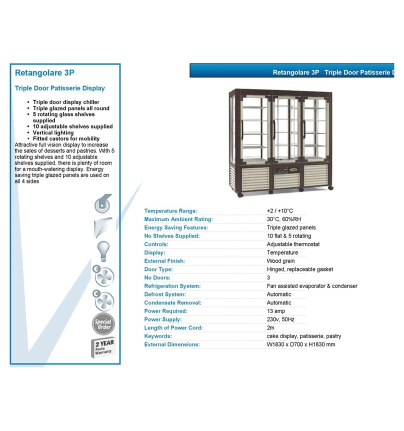
VALERA
VALERA RETANGOLARE 3P datasheet
Crane Merchandising Systems
Crane Merchandising Systems BevMax MEDIA user guide
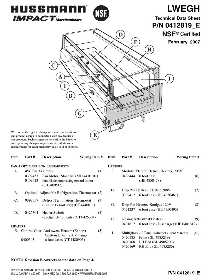
Hussmann
Hussmann IMPACT LWEGH Technical data sheet

Electrolux Professional
Electrolux Professional Kelvinator KCHGICM23FB Installation and service manual


