Hillphoenix UPL-NRG Owner's manual
UPL-NRG
P079451B
Rev. 0 06/10
Table of Contents
Energy Data.......................................................2
Case Dimensions..............................................3
General Information .........................................4
Installation......................................................5-6
Case Connections............................................7
Airflow, Defrost & Temp Control.....................8
Use & Maintenance...........................................9
Parts Ordering ................................................10
Appendix A: Wiring Diagrams
Installation & Operation Handbook
SINGLE-DECK CASE
COMPONENT

ii

Important
DANGER
▲
Indicates an immediate threat of death or se-
rious injury if all instructions are not followed
carefully.
At Hill PHOENIX®, the safety of our customers and employees, as well as
the ongoing performance of our products, are top priorities. To that end, we
include important warning messages in all Hill PHOENIX installation and
operations handbooks, accompanied by an alert symbol paired with the word
"DANGER", "WARNING", or "CAUTION".
All warning messages will inform you of the potential hazard; how to reduce
the risk of case damage, personal injury or death; and what may happen if the
instructions are not properly followed.
WARNING
Indicates a potential threat of death or seri-
ous injury if all instructions are not followed
carefully.
▲
CAUTION
Indicates that failure to properly follow instruc-
tions may result in case damage.
▲
iii

LIABILTY NOTICE
For Cases with Shelf Lighting Systems
Hill PHOENIX does NOT design any of its shelf lighting systems or any of its dis-
play cases with shelf lighting systems for direct or indirect exposure to water or
other liquids. The use of a misting system or water hose on a display case with
a shelf lighting system, resulting in the direct or indirect exposure of the lighting
system to water, can lead to a number of serious issues (including, without limita-
tion, electrical failures, fire, electric shock, and mold) in turn resulting in personal
injury, death, sickness, and/or serious property damage (including, without limita-
tion, to the display itself, to the location where the display is situated [e.g., store]
and to any surrounding property). DO NOT use misting systems, water hoses
or other devices that spray liquids in Hill PHOENIX display cases with lighted
shelves.
If a misting system or water hose is installed or used on a display case with a
shelf lighting system, then Hill PHOENIX shall not be subject to any obligations or
liabilities (whether arising out of breach of contract, warranty, tort [including neg-
ligence], strict liability or other theories of law) directly or indirectly resulting from,
arising out of or related to such installation or use, including, without limitation,
any personal injury, death or property damage resulting from an electrical failure,
fire, electric shock, or mold.
P079211M, REVO
iv

R-744 (CO2) NOTICE
For Systems Utilizing R-744 (CO2) Refrigerant
For refrigeration units that utilize R-744 (CO2), pressure relief and pressure-reg-
ulating relief valves may need to be installed based on the system capacity. The
valves need to be located such that no stop valve is positioned between the relief
valves and the parts or section of the system being protected.
When de-energizing refrigeration units containing R-744 (CO2), venting of the
R-744 (CO2) refrigerant may occur through the pressure regulating relief valves.
These valves are located on the refrigeration system and not on the case model.
If venting does occur, the valve must not be defeated, capped, or altered by any
means.
WARNING: Under no circumstances should any component be replaced or
added without consulting Hill PHOENIX Field Service Engineering. Utilizing
improper components may result in serious injury to persons or damage to
the system.
v

UPL-NRG
ENERGY DATA
Electrical Data
Defrost Controls
1 NOTE: “- - -” not an option on this case model.
2 BTUH/ft notes:
- Listed BTUH/ft indicate parallel operation. Conventional ratings may be approximated by multiplying listed rating by 1.13.
- Add 132 BTUH/ft when aftermarket merchandising accessories are utilized to determine the total BTUH load.
3 Average discharge air velocity at peak of defrost.
Guidelines & Control Settings
Model 2BTUH/ft
Superheat
Set Point @ Bulb
(F)
Evaporator
(F)
Discharge
Air
(F)
Return
Air
(F)
Discharge3
Air Velocity
(FPM)
UPL-NRG 500 6-8 26 30 40 250
Model
Defrosts
per Day
Electric Defrost Timed-Off Defrost Hot Gas Defrost Reverse Air Defrost
Fail-Safe
(min)
Termination
Temp (F)
Fail-Safe
(min)
Termination
Temp (F)
Fail-Safe
(min)
Termination
Temp (F)
Fail-Safe
(min)
Termination
Temp (F)
UPL-NRG 6 - - - - - - 45 42 - - - - - - - - - - - -
Model
Fans
per
Case
High Efciency
Fans
Anti-Condensate
Heaters Defrost Heaters
120 Volts 120 Volts 208 Volts 240 Volts
Amps Watts Amps Watts Amps Watts Amps Watts
UPL-NRG 8’ 2 0.17 20 - - -1- - - - - - - - - - - - - - -
2

CASE DIMENSIONS
NOTES:
* STUB-UP AREA
** RECOMMENDED STUB-UP CENTERL INE FOR ELECTRICAL AND HUB DRA INS
- ENDS ADD APPROXIMATELY 1 INCH TO CASE HEIGHT
- A 2" M INIMUM AIR GAP IS REQUIRED BETWEEN THE REAR OF THE CASE AND A WALL
- BACK PANELS ADD APPROXIMATELY 1" TO THE REAR OF THE CASE
35 1/16 in
[89.1 cm]
**
39 3/8 in
[99.9 cm]
41 5/16 in
[104.9 cm]
31 11/16 in
[80.5 cm]
FRONT OF CASE
C
L
1 1/2 in [3.8 cm]{END}
96 in [243.8 cm] (8' CASE)
35 7/16 in
[90.0 cm]
46 7/16 in
[117.9 cm]
48 7/16 in
[123.1 cm]
8 5/8 in [21.9 cm]
33 1/4 in [84.4 cm]
25 1/16 in
[63.6 cm] 8 in
[20.3 cm]
3 13/16 in [9.7 cm]
22 11/16 in
[57.6 cm]
16 13/16 in [42.7 cm]
8 11/16 in [22.1 cm]
4 in[10.2 cm] 28 5/8 in
[72.7 cm]
REFRIGERATION
REAR REFRIGERATION
(11 3/4" OFF OF FLOOR)
22 9/16 in [57.3 cm]
20 1/16 in [51.0 cm]
35 3/16 in
[89.4 cm]
1 1/2" PVC DRAIN
CONNECTION
33 9/16 in
[85.3 cm]
6 13/16 in [17.2 cm]*
31 11/16 in [80.5 cm]
39 3/8 in [99.9 cm]
5 1/8 in
[13.1 cm]
41 5/16 in [104.9 cm]
JUNCTION BOX
(STANDARD)
ELECTRICAL
3

Thank you for choosing Hill PHOENIX for your food merchandising needs. This handbook contains important technical
information and will assist you with the installation and operation of your new Hill PHOENIX display cases. By closely fol-
lowing the instructions, you can expect peak performance; attractive fit and finish; and long case life.
We are always interested in your suggestions for improvements (e.g. case design, technical documents, etc.). Please feel
free to contact our Marketing Services group at the toll-free number listed below. Thank you for choosing Hill PHOENIX,
and we wish you the very best in outstanding food merchandising.
GENERAL INFORMATION
CASE DESCRIPTION
This manual specifically covers the UPL-NRG single-deck
produce merchandiser.
STORE CONDITIONS
Hill PHOENIX cases are designed to operate in an air-con-
ditioned store that maintains a 75°F (24°C) store tempera-
ture and 55% (max) relative humidity (CRMA conditions).
Case operation will be adversely affected by exposure to
excessively high ambient temperatures and/or humidity.
REFRIGERATION SYSTEM OPERATION
Air-cooled condensing units require adequate ventilation
for efficient performance. Machine-room temperatures
must be maintained at a minimum of 65°F in winter and a
maximum of 95°F in summer. Minimum condensing tem-
peratures should be no less than 70°F.
RECEIVING CASES
Examine fixtures carefully and in the event of shipping
damage and/or shortages, please contact the Service
Parts Department at the toll-free number listed below.
CASE DAMAGE
Claims for obvious damage must be 1) noted on either the
freight bill or the express receipt and 2) signed by the carri-
er's agent; otherwise, the carrier may refuse the claim. If
damage becomes apparent after the equipment is
HILL PHOENIX
1925 Ruffin Mill Rd.
Colonial Heights, VA 23834
Mon.-Fri. (8 a.m to 5 p.m EST)
Tel: 1-800-283-1109/Fax: 804-526-7450
Web site: www.hillphoenix.com
unpacked, retain all packing materials and submit a written
request to the carrier for inspection within 14 days of
receipt of the equipment.
LOST/MISSING ITEMS
Equipment has been carefully inspected to insure the high-
est level of quality. Any claim for lost/missing items must
be made to Hill PHOENIX within 48 hours of receipt of the
equipment.
TECHNICAL SUPPORT
For technical questions regarding display cases, please
contact our Case Division Customer Service Department at
the toll-free number listed below. For questions regarding
our refrigeration systems or electrical distribution centers,
please contact our Systems Division Customer Service
Department at 1-770-388-0706.
CONTACTING THE FACTORY
If you need to contact Hill PHOENIX regarding a specific
fixture, be certain that you have both the case model num-
ber and serial number (this information can be found on
the serial plate, located on the upper top flue panel on the
right-hand side). When you have this information, call the
toll-free number below and ask for a Service Parts
Representative.
4

INSTALLATION
MOVING CASES
Hill PHOENIX display cases are generally shipped to
stores with casters installed on the base frame. The cast-
ers make the job of moving cases easier for everyone
involved in the shipping and installation process, as well as
reducing the chance of damage from raising and lowering
cases with ”J” bars to place them on dollies, skates or roll-
ers. In most situations, one or two persons can easily
move the case into position.
When the cases arrive at the store, simply roll them on to
the store floor to the proper staging area. Occasionally,
cases are shipped with skid boards attached to help with
stabilization. In these instances, the casters should be
attached after the case is removed from the truck.
Removing the casters is an easy process. Simply flatten
and remove the cotter pins that are holding the casters in
place (Fig. 1). Then lift the case with a “J” bar and slide
the caster assemblies out. The dismantled casters can
now be discarded.
FLOOR PREP
1. Ask the general contractor if your current copy of the
building dimensions are the most recently issued. Also,
ask for the points of reference from which you should
take dimensions to locate the cases.
2. Using chalk lines or a laser transit, mark the floor
where the cases are to be located for the entire lineup.
The lines should coincide with the outside edges of the
case feet.
3. Leveling is necessary to ensure proper case align-
ment and to avoid potential case damage. Locate the
highest point on the positioning lines as a reference for
determining the proper height of the shim-pack level-
ers. A laser transit is recommended for precision and
requires just one person.
4. Locate basehorse positions along the chalk line. Spot
properly leveled shim packs at each basehorse loca-
tion.
Fig. 1 Caster assembly
CASTER
WARNING
Be certain that your hands and feet are out of
the way before lowering the case after the
removal of the casters. Failure to do so may
result in serious injury.
▲
J-BAR
LINE-UP & INSTALLATION
Single Case
1. Roll the case into position. Using a “J” bar , raise the
end of the case (under cross support), remove the
caster assembly and lower the basehorse on to the
shim packs. Repeat on the other end of the case.
2. Once the basehorse is properly placed on the shim
packs, check the vertical plumb of the case by plac-
ing a bubble level on the rear wall. Add/remove shim
packs as needed. To check the horizontal level, repeat
this process after placing the bubble level on the front
sill.
Multi-Case
1. Remove any loose items from the cases that may
interfere with case joining (e.g. shipping braces, mirror
assemblies, etc). Be certain to keep all loose items
close to the case in which they shipped as they will
be used later in the installation process.
2. Follow the single-case installation instructions (above)
for the first case, then position the next case in the line-
up approximately 3’ away. Remove the casters on the
end that is closest to the first case.
3. Apply the foam tape gasket (supplied) and a bead of
butyl or silicone sealant to the end breaker of the first
case. From the opposite end, push the second case to
a position that is approximately 6" from the first case,
then remove the remaining casters and position case
on the shim packs.
4. Push the cases tightly together, then lightly bolt them
together through the holes that are provided. Tighten
all the joining bolts until all margins are equal. Be care-
ful not to over tighten.
5. Repeat steps 3 and 4 of this sequence for all remaining
cases. Be certain to properly level all cases.
5
TRIM OUT
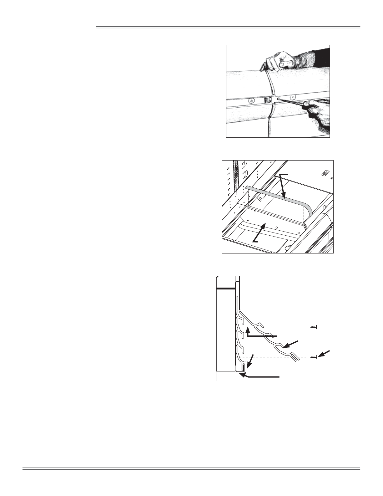
1. If a master bumper is included, locate the hole in the
center of the master bumper joint. Using a screw driver
as a lever, slide the case-to-case joint to the center of
the joint between the two cases (Fig. 2). Slide the mas-
ter bumpers left or right to close the seams as required,
working outwards from the center of the line-up to the
ends.
2. Close the seam where the bumper joins the case end.
The bumper joint closes the seam that may develop
if the master bumper is moved away from the end to
close the case-to-case joint seam.
3. Seal the case-to-case joints with caulk (supplied), then
apply acrylic tape (supplied) over the pipe-chase seam
(Fig. 3). The tape acts as a watershed preventing wa-
ter from settling in the case joint.
4. Close the joints of the front panel, sliding the joint trim
left-or-right as needed.
5. Attach the “J” rail with the supplied screws (Fig. 4).
6. Insert top of kickplate into the kickplate retainer. Slide
the kickplate up into the retainer, then down onto the “J”
rail (Fig. 4). Be certain that the bottom of the kickplate
is fitted over extruding "lip" of the "J" rail.
7. If a master bumper is present, insert nose bumper
into master bumper channel. Roll nose bumper into
channel along entire lineup, up to 96’. We recommend
leaving an additional 6" of nose bumper at the ends to
allow for shrinkage during the first 24-48 hours follow-
ing case start-up.
8. After sufficient time has passed to allow for bumper
shrinkage, cut away the excess bumper for final fit and
finish. Be certain to use an appropriate cutting tool
(tubing- or PVC-cutter) to ensure a smooth cut.
Fig. 3 Sealing the pipe chase
PIPE
CHASE
ACRYLIC
TAPE
Fig. 2 Case-to-case joint
INSTALLATION
Fig. 4 "J" rail and kickplate installation
1. Attach "J" rail using
supplied screws.
2. Slide kickplate UP into
kickplate retainer recess.
3. Drop the kickplate
DOWN onto the "J" rail lip.
KICKPLATE
2
3
"J" RAIL
1
6

CASE CONNECTIONS
REFRIGERATION
As the diagram below indicates, the coil outlet hole is
positioned forward on the right-hand side of the case, fully
visible in front of the fan plenum.
The expansion valve and other controls - located on the
left-hand side of the case - are accessible without lifting the
fan plenum and may be reached by lifting the deck pans.
If it becomes necessary to penetrate the case bottom, be
certain to seal it afterwards with canned-foam sealant and
white RTV.
PLUMBING
The drain outlet is specially molded out of PVC material
and is located in the center of the case for convenient ac-
cess. The “P” trap, furnished with the case, is constructed
of schedule 40 PVC pipe. Care should be given to ensure
that all connections are water-tight and sealed with the ap-
propriate PVC or ABS cement.
The drain lines can be run left or right of the tee with the
proper pitch to satisfy local drainage requirements. Since
the kickplate is shipped loose with the case, you should
have open access to the drain line area during installation.
35 1/16 in
[89.1 cm]
**
39 3/8 in
[99.9 cm]
41 5/16 in
[104.9 cm]
31 11/16 in
[80.5 cm]
FRONT OF CASE
C
L
1 1/2 in [3.8 cm]{END}
96 in [243.8 cm] (8' CASE)
8 11/16 in [22.1 cm]
4 in[10.2 cm] 28 5/8 in
[72.7 cm]
REFRIGERATION
REAR REFRIGERATION
(11 3/4" OFF OF FLOOR)
22 9/16 in [57.3 cm]
20 1/16 in [51.0 cm]
35 3/16 in
[89.4 cm] JUNCTION BOX
(STANDARD)
ELECTRICAL
1 1/2" PVC DRAIN
CONNECTION
33 9/16 in
[85.3 cm]
MODEL
UPL-NRG
REMOVE THE SHIPPING BLOCKS THAT PROTECT THE
REFRIGERATION LINES DURING SHIPMENT BEFORE
OPERATING THE CASE.
REMOVE
If the kickplate has been installed, you will find it very easy
to remove. Simply lift the kickplate up from the "J" rail and
pull it out, away from the case. See the Trim Out section
on page 6.
ELECTRICAL
Electrical hookups are made to a junction box located at
the bottom-left-front of the case.
For case-to-case wiring, run conduit between the junction
boxes. When connecting to the junction box on the bottom-
left side of the case, field wiring should exit box from the
right side (furthest away from case wiring) to allow more
room inside for wiring connections.
CAUTION
If any brazing is necessary, place wet rags
around the area to avoid tank damage.
▲
7
AIRFLOW, DEFROST & TEMP CONTROLS
case on the bottom-left side (Fig. 5). To access the thermo-
stats, you must first remove the kick plate, then remove the
junction box cover. For instructions on removing the kick-
plate, see the Trim Out section of this manual on page 6.
It is important to consult the control setting guidelines shown
on page 2 before setting defrost times. Further adjustment
may be required depending on store conditions.
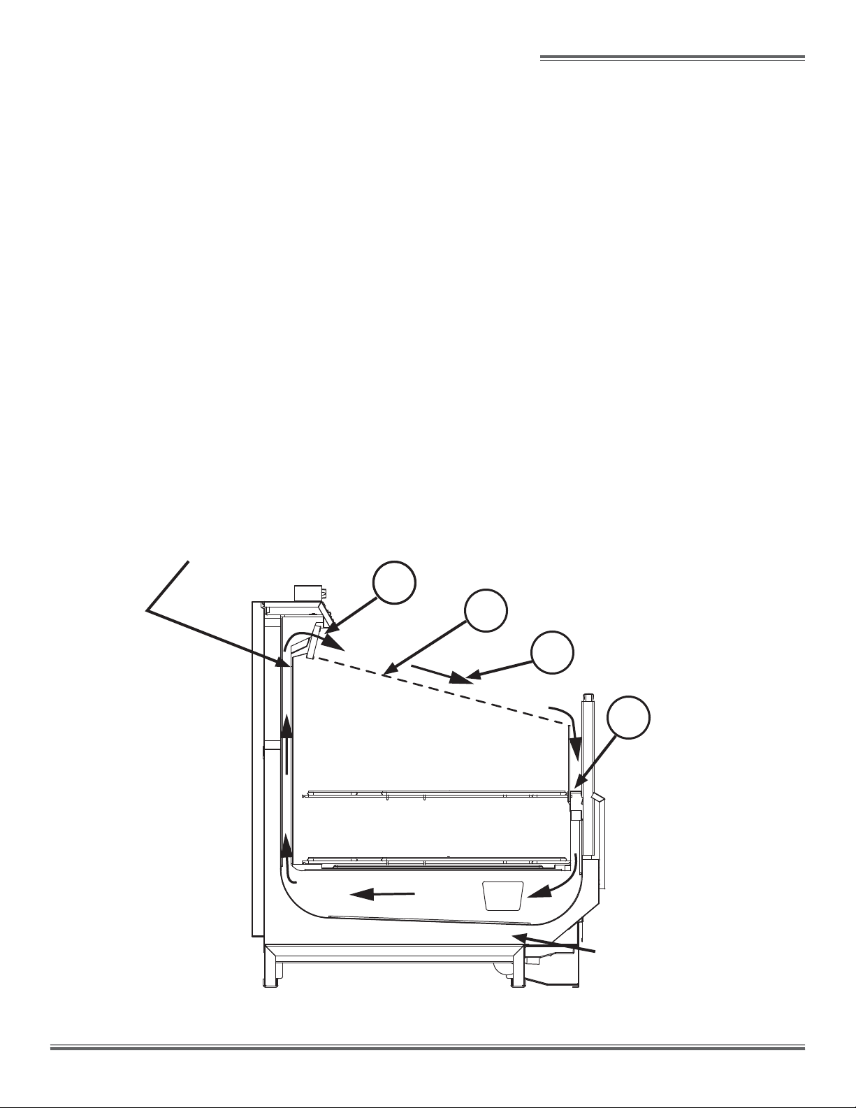
AIR FLOW & PRODUCT LOAD
Hill PHOENIX cases provide maximum product capacity
within the refrigerated air envelope. Please keep products
within the load limit line shown on the diagram below.
It is important that you do not overload the food product dis-
play so that it impinges on the air flow pattern. Overloading
will cause malfunction and the loss of proper temperature
levels, particularly when discharge and return air sections
are covered.
DEFROST & TEMPERATURE CONTROLS
UPL-NRG cases are equipped with Timed-Off defrost.
The rear baffle (Fig. 5) contains the sensor bulb for tem-
perature control and the discharge air probe. The defrost
termination control thermostat and the temperature control
thermostat are located in the junction box underneath the
Fig. 5 Airflow; probe, sensor locations.
Temperature control sensor bulb
Discharge air probe
Defrost termination control thermostat
Temperature control thermostat
MODEL
UPL-NRG
1. DISCHARGE AIR
2. LOAD LIMIT
3. AIR CURTAIN
4. RETURN AIR
1
1
2
3
4
8
SINGLE PIECE FAN PLENUM LIFT UP
PLENUM
COVER
COIL
COVER
SINGLE PIECE FAN
PLENUM SWINGS UP
FOR EASY CLEANING
USE & MAINTENANCE
CLEANING PROCEDURES
• A periodic cleaning schedule should be established to
maintain proper sanitation, insure maximum operating
efficiency, and avoid the corrosive action of food fluids
on metal parts that are left on for long periods of time.
We recommend cleaning once a week.
• To avoid shock hazard, be sure all electrical power is
turned off before cleaning. In some installations, more
than one disconnect switch may have to be turned off to
completely de-energize the case.
• All surfaces pitch downward to a deep-drawn drain
trough, funneling liquids/ to the front of the case where
the waste outlet is located for easy access. Check
waste outlet to insure it is not clogged before starting
the cleaning process and avoid introducing water faster
than the case drain can carry it away.
• The coil is covered to keep food fluids from entering
but is easily accessible when coil cleaning is required.
Simply remove the screws; lift and remove the plenum
cover; then lift and remove the coil cover. Be certain that
both the plenum and coil cover are properly closed and
secured after cleaning to avoid air leaks.
• If any potentially harmful cleaners are used, be certain
to provide a temporary separator (e.g., cardboard, plas-
tic rap, etc.) between those cases that are being cleaned
and those that may still contain product.
• Avoid spraying cleaning solutions directly on electrical
connections.
• Allow cases to be turned off long enough to clean any
frost or ice from coil and pans.
• Remove kickplate and clean underneath the case with a
broom and a long-handled mop. Use warm water and a
disinfecting cleaning solution when cleaning underneath
the cases.
DANGER
▲
SHOCK HAZARD
Always disconnect power to case when servic-
ing or cleaning. Failure to do so may result in
serious injury or death.
WARNING
▲
Exercise extreme caution when working in a
case with the coil cover removed. The coil
contains many sharp edges that can result in
severe cuts to the hands and arms.
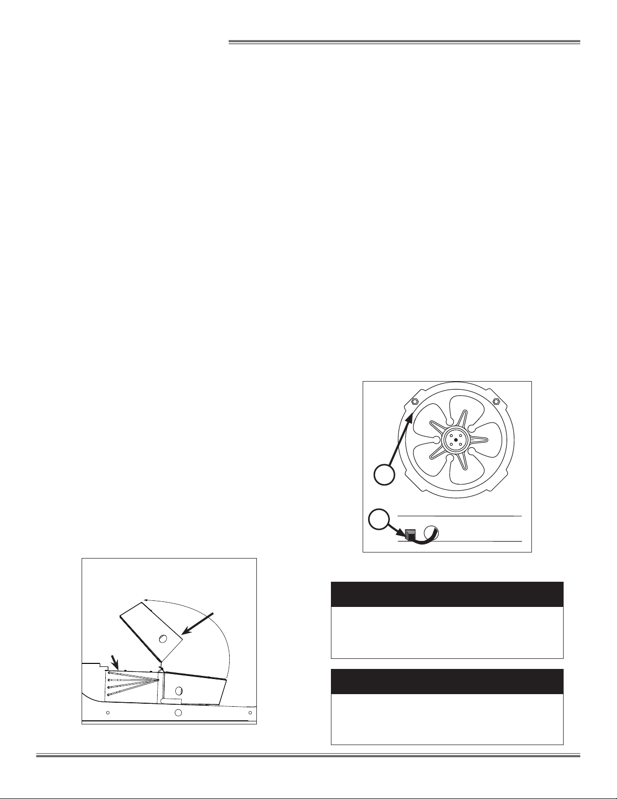
FANS
The evaporator fans are equipped with 16-watt fan motors.
Motors have a counter-clockwise rotation when viewed
from the shaft end.
The fan blades are 8” in diameter with a 20fan blade
pitch. It is important that the blade pitch be maintained as
installed. Do not attempt a field modification by alter-
ing the blades.
Fan motors may be changed with an easy two-step pro-
cess without lifting up the plenum, thereby avoiding the
necessity to unload the entire product display to make a
change:
1. Unplug the fan motor, easily accessible outside the
plenum. Push power cord back through plenum
opening.
2. Remove two fasteners, then lift out the entire fan
basket.
Reverse procedure when re-installing fan basket.
FAN ASSEMBLY
1
2
9

Contact the Service Parts Department at:
1-800-283-1109
Provide the following information about the part you are
ordering:
• Model number and serial number of the case for
which the part is intended.
• Length of the part (if applicable).
• Color of part (if painted) or color of polymer part.
• Whether part is for left- or right-hand application.
• Quantity
*Serial plate is located on the back of the case on the right-hand side.
If the parts are to be returned for credit, ask the Parts
Department to furnish you with a Return Material
Authorization Number.
PARTS ORDERING
10

APPENDIX A:
WIRING DIAGRAMS


NOTES

NOTES

06/00
WARRANTY
HEREINAFTER REFERRED TO AS MANUFACTURER
FOURTEEN MONTH WARRANTY. MANUFACTURER’S PRODUCT IS WARRANTED TO BE FREE FROM DEFECTS
IN MATERIAL AND WORKMANSHIP UNDER NORMAL USE AND MAINTENANCE FOR A PERIOD OF FOURTEEN
MONTHS FROM THE DATE OF ORIGINAL SHIPMENT. A NEW OR REBUILT PART TO REPLACE ANY
DEFECTIVE PART WILL BE PROVIDED WITHOUT CHARGE, PROVIDED THE DEFECTIVE PART IS RETURNED TO
MANUFACTURER. THE REPLACEMENT PART ASSUMES THE UNUSED PORTION OF THE WARRANTY.
This warranty does not include labor or other costs incurred for repairing, removing, installing, shipping, servicing, or
handling of either defective parts or replacement parts.
The fourteen month warranty shall not apply:
1. To any unit or any part thereof which has been subject to accident, alteration, negligence, misuse or
abuse, operation on improper voltage, or which has not been operated in accordance with the
manufacturer’s recommendation, or if the serial number of the unit has been altered, defaced, or removed.
2. When the unit, or any part thereof, is damaged by fire, flood, or other act of God.
3. Outside the continental United States.
4. To labor cost for replacement of parts, or for freight, shipping expenses, sales tax or upgrading.
5. When the operation is impaired due to improper installation.
6. When installation and startup forms are not properly complete or returned within two weeks after startup.
THIS PLAN DOES NOT COVER CONSEQUENTIAL DAMAGES. Manufacturer shall not be liable under any circumstanc-
es for any consequential damages, including loss of profit, additional labor cost, loss of refrigerant or food products,
or injury to personnel or property caused by defective material or parts or for any delay in its performance hereunder
due to causes beyond its control. The foregoing shall constitute the sole and exclusive remedy of any purchases
and the sole and exclusive liability of Manufacturer in connection with this product.
The Warranties are Expressly in Lieu of All Other Warranties, Express of Implied and All Other Obligations or
Liabilities on Our Part. The Obligation to Repair or Replace Parts or Components Judged to be Defective in
Material or Workmanship States Our Entire Liability Whether Based on Tort, Contract or Warranty. We Neither
Assume Nor Authorize Any Other Person to Assume for Us Any Other Liability in Connection with Our Product.
MAIL CLAIM TO:
Hill PHOENIX
Display Merchandisers
1925 Ruffin Mill Road
Colonial Heights, VA 23834
1-800-283-1109
Hill PHOENIX
Refrigeration Systems &
Electrical Distribution Products
709 Sigman Road
Conyers, GA 30013
770-285-3200

Warning
Maintenance & Case Care
When cleaning cases the following must be performed
PRIOR to cleaning:
To avoid electrical shock, be sure all electric power is
turned off before cleaning. In some installations, more
than one switch may have to be turned off to complete-
ly de-energize the case.
Do not spray cleaning solution or water directly on fan
motors or any electrical connections.
All lighting receptacles must be dried off prior to inser-
tion and re-energizing the lighting circuit.
Please refer to the Use and Maintenance section of this installation manual.
BDM0610
1925 Ruffin Mill Road, Colonial Heights, VA 23834
Due to our commitment to continuous improvement, all specifications are subject to change without notice.
Hill PHOENIX is a Sustaining Member of the American Society of Quality.
Visit our web site at www.hillphoenix.com
Tel: 1-800-283-1109
Table of contents
Other Hillphoenix Merchandiser manuals


Popular Merchandiser manuals by other brands

Polar Electro
Polar Electro CD229-A instruction manual

Structural Concepts
Structural Concepts Harmony HMG3953 Installation and operating manual

Hussmann
Hussmann P4NX-EP Technical data sheet

Lincat
Lincat SCR785 User and installation instructions

Hussmann
Hussmann LG installation instructions

saro
saro SC 70 Operation instructions


Summit
Summit Classic CL181WBV instruction manual

Hussmann
Hussmann HEDN Installation and operation guide

Howard McCray
Howard McCray R-CFS35-10 Specifications

Hussmann
Hussmann impact Excel C5X-LEP Technical data sheet

Delfield
Delfield Shelleyspeed SPH-40E Specifications

Lincat
Lincat Seal C6A/75B Installation, operating and servicing instructions