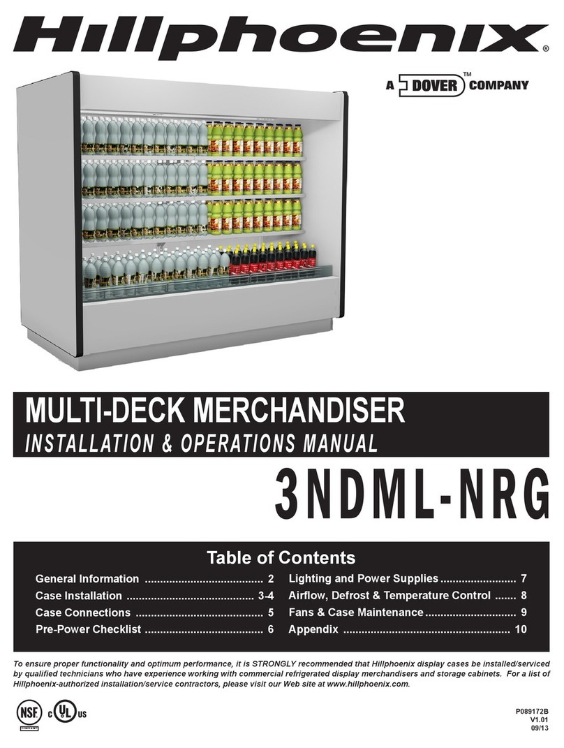
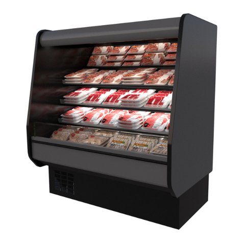
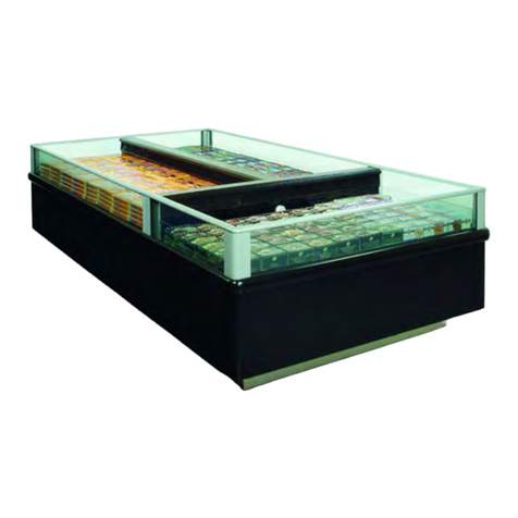
Hillphoenix OB-SC R-290 PRODUCE User manual

OB-SC (R-290)
PRODUCE
12/20
SINGLE/MULTI-DECK MERCHANDISER
I N S TA L L AT I O N & O P E R AT I O N S M A N U A L
Technical References ................................................. 2-7
General Information ........................................................8
Installation ................................................................ 9-10
Case Connections ...................................................11-12
Pre-Power Checklist .................................................... 13
Airflow & Defrost .......................................................... 14
Case Cleaning .........................................................15-17
Troubleshooting ........................................................... 18
Safety Devices & Service .......................................19-20
Parts Ordering .............................................................. 21
Appendices
Table of Contents
To ensure proper functionality and optimum performance, it is STRONGLY recommended that Hillphoenix specialty cases be installed/serviced by qualified tech-
nicians who have experience working with commercial refrigerated display merchandisers and storage cabinets. For a list of Hillphoenix-authorized installation/
service contractors, please visit our website at www.hillphoenix.com.

ii

Important
D A N G E R
•
Indicates an immediate threat of death or seri-
ous injury if all instructions are not followed
carefully.
At Hillphoenix®, the safety of our customers and employees, as well as the ongo-
ing performance of our products, are top priorities. To that end, we include impor-
tant warning messages in all Hillphoenix installation and operations handbooks,
accompanied by an alert symbol paired with the word "DANGER", "WARNING", or
"CAUTION".
All warning messages will inform you of the potential hazard; how to reduce the
risk of case damage, personal injury or death; and what may happen if the in-
structions are not properly followed.
This manual must be stored near the display case where it can be easily consult-
ed. If this manual does not provide the information you require please contact
Hillphoenix for more information.
W A R N I N G
Indicates a potential threat of death or serious
injury if all instructions are not followed care-
fully.
•
C A U T I O N
Indicates that failure to properly follow instruc-
tions may result in case damage.
•
iii

Revision History
• new manual format_09/20
• NSF Listing Update_12/20
iv

TECHNICAL REFERENCE
A
LL MEASUREMENTS ARE TAKEN PER
A
SHRAE-72-2005 SPECIFICATIONS. HILLPHOENIX
REFRIGERATED DISPLAY CASES FOR SALE IN THE
UNITED STATES MEET OR EXCEED DEPARTMENT
OF ENERGY 2017 REQUIREMENTS.
OB-SC Self-Service Open Multi-Deck Tiered Bulk Produce Merchandise
r
1, 2 & 4 Tier (Produce)
OB-SC
Rev. Date Rev. # Rev. Title
06-17-20 1 NEW STANDARDS
GENERAL NOTES:
• "---" Indicates that the feature is not an option on this case model and/or the data is not yet available at this time.
SHIPPING WEIGHT
Case Weight
OB-SC ---
2

TECHNICAL REFERENCE
A
LL MEASUREMENTS ARE TAKEN PER
A
SHRAE-72-2005 SPECIFICATIONS. HILLPHOENIX
REFRIGERATED DISPLAY CASES FOR SALE IN THE
UNITED STATES MEET OR EXCEED DEPARTMENT
OF ENERGY 2017 REQUIREMENTS.
OB-SC Self-Service Open Multi-Deck Tiered Bulk Produce Merchandise
r
1, 2 & 4 Tier (Produce)
OB-SC
Rev. Date Rev. # Rev. Title
06-17-20 1 NEW STANDARDS
NOTES:
• "---" Indicates that the feature is not an option on this case model and/or the data is not yet available at this time.
• Listed discharge air velocity represents the average velocity at the peak of defrost measured from front facing
discharge wall vents to lower tier.
• RLA - Running Load Amps
• LRA - Locked Rotor Amps
SYSTEM REQUIREMENTS
Case
Length Volts Phase
Total
Amps
Minimum
Circuit
Ampacity
Maximum
Overcurrent
Protection
1 Tier 120 1 6.03 7.36 12.66
2 Tier 120 1 9.23 11.33 19.73
4 Tier 120 1 18.46 20.56 28.96
ELECTRICAL DATA
Case
Length
Fans Per
Case Volts
High Efficiency
Fans
Condenser
Fans
Amps Watts Amps Watts
1 Tier 1 120 0.30 25.0 0.43 25.0
2 Tier 1 120 0.30 25.0 0.53 30.0
4 Tier 2 120 0.60 50.0 1.06 60.0
GUIDELINES AND CONTROL SETTINGS
24hr Energy
Usage
(kWh/ft)
Suction Temperature
@ Case Outlet
(°F)
Superheat
Set Point @ Bulb
(°F)
Discharge Air
(°F)
Discharge Air
Velocity
(FPM)
--- 10 -15 Capillary Tube 28 150 -170
CONDENSING UNIT DATA
Case
Length Volts Phase BTUHs
RLA
(Amps)
LRA
(Amps)
Compressor
Qty Refrig. Qty Grams
1 Tier 120 1 2957 5.3 32.0 1 R290 1 126
2 Tier 120 1 3876 8.4 41.5 1 R290 1 90
4 Tier 120 1 3876 8.4 41.5 2 R290 2 90
DEFROST CONTROLS
Defrosts
Per Day
Run-Off
Time
(Min)
Electric Defrost Timed-Off Defrost Hot Gas Defrost
Fail-Safe
(Min)
Termination
Temp
(°F)
Fail-Safe
(Min)
Termination
Temp
(°F)
Fail-Safe
(Min)
Termination
Temp
(°F)
6 --- --- --- 45 46 --- ---
3

TECHNICAL REFERENCE
PLEX
45 9/16" [115.7 cm]
PLEX
5 1/2" [14.0 cm]
31" [78.7 cm]
FRAME
40" [101.6 cm]
WOOD
40 3/4" [103.5 cm]
8" [20.3 cm]
34 1/2" [87.6 cm]
COMPRESSOR COMPARTMENT
(AIR FLOW BACK TO FRONT)
3" CRITICAL TEMP LOAD LIMIT
6" NON-CRITICAL TEMP LOAD LIMIT
PRODUCT STOP
23 5/8" [60.0 cm]
5" [12.7 cm]
8" [20.3 cm]
OVERALL
34 1/2" [87.6 cm]
TOEKICK
27" [68.6 cm]
PLEX
31" [78.7 cm]
POWER SUPPL
Y
FRONT OF CASE
A
LL MEASUREMENTS ARE TAKEN PER
A
SHRAE-72-2005 SPECIFICATIONS. HILLPHOENIX
REFRIGERATED DISPLAY CASES FOR SALE IN THE
UNITED STATES MEET OR EXCEED DEPARTMENT
OF ENERGY 2017 REQUIREMENTS.
OB-SC Self-Service Open Multi-Deck Tiered Bulk Produce Merchandise
r
1, 2 & 4 Tier (Produce)
OB-SC
Rev. Date Rev. # Rev. Title
06-17-20 1 NEW STANDARDS
NOTES:
• Shown with optional wood cladding.
4

TECHNICAL REFERENCE
32 3/4" [83.1 cm] 32 3/4" [83.1 cm]
WOOD
28 15/16" [73.5 cm]
PLEX
33 3/4" [85.7 cm]
34 1/2" [87.6 cm] 34 1/2" [87.6 cm]
PLEX
5 1/2" [14.0 cm]
FRAME
28 3/16" [71.6 cm]
PLEX
38 1/16" [96.7 cm]
WOOD
33 1/4" [84.5 cm]
FRAME
32 1/2" [82.6 cm]
8" [20.3 cm]
69" [175.3 cm]
MID DECK
LOWER DECK
COMPRESSOR COMPARTMENT
(AIR FLOW BACK TO FRONT)
3" CRITICAL TEMP LOAD LIMIT
6" NON-CRITICAL TEMP LOAD LIMIT
3" CRITICAL TEMP LOAD LIMIT
6" NON-CRITICAL TEMP LOAD LIMIT
64" [162.6 cm]
28 1/2" [72.3 cm] 29" [73.7 cm]
5" [12.7 cm]
OVERALL
34 1/2" [87.6 cm]
26 5/8" [67.6 cm]
OVERALL
69" [175.3 cm]
PRODUCT STOP
23 5/8" [60.0 cm]
TOEKICK
27" [68.6 cm]
PLEX
31" [78.7 cm]
FRONT OF CASEPOWER SUPPL
Y
MID DECK LOWER DECK
A
LL MEASUREMENTS ARE TAKEN PER
A
SHRAE-72-2005 SPECIFICATIONS. HILLPHOENIX
REFRIGERATED DISPLAY CASES FOR SALE IN THE
UNITED STATES MEET OR EXCEED DEPARTMENT
OF ENERGY 2017 REQUIREMENTS.
OB-SC Self-Service Open Multi-Deck Tiered Bulk Produce Merchandise
r
1, 2 & 4 Tier (Produce)
OB-SC
Rev. Date Rev. # Rev. Title
06-17-20 1 NEW STANDARDS
NOTES:
• Shown with optional wood cladding.
5

TECHNICAL REFERENCE
32 3/4" [83.2 cm]32 3/4" [83.2 cm]
PLEX
38 1/16" [96.7 cm]
5 1/2" [14.0 cm]
FRAME
32 1/2" [82.6 cm]
WOOD
33 1/4" [84.5 cm]
PLEX
44 13/16" [113.8 cm]
WOOD
40" [101.6 cm]
FRAME
39 1/4" [99.7 cm]
8" [20.3 cm]
34 1/2" [87.6 cm] 34 1/2" [87.6 cm]
69" [175.3 cm]
PLEX
38 1/16" [96.7 cm]
WOOD
33 1/4" [84.5 cm]
FRAME
32 1/2" [82.6 cm]
8" [20.3 cm]
69" [175.3 cm]
34 1/2" [87.6 cm] 34 1/2" [87.6 cm]
32 3/4" [83.2 cm] 32 3/4" [83.2 cm]
UPPER DECK
MID DECK
5 1/2" [14.0 cm]
PLEX
33 3/4" [85.7 cm]
WOOD
28 15/16" [73.5 cm]
FRAME
28 3/16" [71.6 cm]
MID DECK
LOWER DECK
COMPRESSOR COMPARTMENT
(AIR FLOW BACK TO FRONT)
3" CRITICAL TEMP LOAD LIMIT
6" NON-CRITICALTEMP LOAD LIMIT
3" CRITICAL TEMP LOAD LIMIT
6" NON-CRITICAL TEMP LOAD LIMIT
3" CRITICAL TEMP LOAD LIMIT
6" NON-CRITICAL TEMP LOAD LIMIT
3" CRITICAL TEMP LOAD LIMIT
6" NON-CRITICAL LOAD LIMIT
A
LL MEASUREMENTS ARE TAKEN PER
A
SHRAE-72-2005 SPECIFICATIONS. HILLPHOENIX
REFRIGERATED DISPLAY CASES FOR SALE IN THE
UNITED STATES MEET OR EXCEED DEPARTMENT
OF ENERGY 2017 REQUIREMENTS.
OB-SC Self-Service Open Multi-Deck Tiered Bulk Produce Merchandise
r
1, 2 & 4 Tier (Produce)
OB-SC
Rev. Date Rev. # Rev. Title
06-17-20 1 NEW STANDARDS
NOTES:
• Shown with optional wood cladding.
6

TECHNICAL REFERENCE
OVERALL
69" [175.3 cm]
PLEX
65 3/8" [166.1 cm]
28 7/16" [72.2 cm] 29 1/16" [73.8 cm]
PLEX
65 1/2" [166.4 cm]
26 5/8" [67.6 cm]
OVERALL
69" [175.3 cm]
28 7/16" [72.2 cm]29 1/16" [73.8 cm]
5" [12.7 cm]
UPPER
DECK
MID
DECK
MID
DECK
LOWER
DECK
FRONT OF CASE
POWER SUPPL
Y
TOEKCIK
61 1/2" [156.2 cm]
A
LL MEASUREMENTS ARE TAKEN PER
A
SHRAE-72-2005 SPECIFICATIONS. HILLPHOENIX
REFRIGERATED DISPLAY CASES FOR SALE IN THE
UNITED STATES MEET OR EXCEED DEPARTMENT
OF ENERGY 2017 REQUIREMENTS.
OB-SC Self-Service Open Multi-Deck Tiered Bulk Produce Merchandise
r
1, 2 & 4 Tier (Produce)
OB-SC
Rev. Date Rev. # Rev. Title
06-17-20 1 NEW STANDARDS
7

Thank you for choosing Hillphoenix for your food merchandising needs. This handbook contains important technical infor-
mation and will assist you with the installation and operation of your new Hillphoenix specialty cases. By closely following
the instructions, you can expect peak performance; attractive fit and finish; and long case life.
We are always interested in your suggestions for improvements (e.g. case design, technical documents, etc.). Please feel
free to contact our Marketing Services group at the number listed below. Thank you for choosing Hillphoenix, and we wish
you the very best in outstanding food merchandising.
CASE DESCRIPTION
This manual specifically covers the OB-S (R-290) produce self-
service open single/multi-deck merchandiser.
STORE CONDITIONS
Hillphoenix cases are designed to operate in an air-condi-
tioned store that maintains a 75°F (24°C) store temperature
and 55% (max) relative humidity (ASHRAE conditions). Case
operation will be adversely affected by exposure to excessively
high ambient temperatures and/or humidity.
REFRIGERATION SYSTEM OPERATION
Air-cooled condensing units require adequate ventilation for
efficient performance.
THIS UNIT CONTAINS R-290 FLAMMABLE REFRIGERANT. USE
CAUTION WHEN HANDLING, MOVING OR SERVICING THE DISPLAY
CASE. AVOID DAMAGING THE REFRIGERANT TUBING WHICH COULD
INCREASE THE RISK OF A LEAK.
SHIPPING CASES
Transportation companies assume all liability from the time a
shipment is received by them until the time it is delivered to
the consumer. Our liability ceases at the time of shipment.
RECEIVING CASES
Examine fixtures carefully and in the event of shipping dam-
age and/or shortages, please contact the Service Parts
Department at the number listed below.
CASE DAMAGE
Claims for obvious damage must be 1) noted on either the
freight bill or the express receipt and 2) signed by the carrier's
agent; otherwise, the carrier may refuse the claim. If damage
becomes apparent after the equipment is unpacked, retain all
packing materials and submit a written request to the carrier
for inspection within 14 days of receipt of the equipment.
Failure to follow this procedure will result in refusal by the
carrier to honor any claims with a consequent loss to the
consumer.
If a UPS shipment has been damaged, retain the damaged
material, the carton and notify us at once. We will file a claim.
LOST/MISSING ITEMS
Equipment has been carefully inspected to insure the highest
level of quality. Any claim for lost/missing items must be
made to Hillphoenix within 48 hours of receipt of the equip-
ment. When making a claim please use the number listed
below.
SERVICE PARTS & TECHNICAL SUPPORT
For service parts questions regarding our cases, please
contact our Service Parts Department at 1-844-HPX-PART
For technical questions regarding our cases, please contact
our Technical Support Department at 1-833-280-5714.
CONTACTING THE FACTORY
If you need to contact Hillphoenix regarding a specific fixture,
be certain that you have both the case model number and
serial number. (This information can be found on the data tag,
located at the top-left interior, rear exterior panel or interior
rear lower storage of the case. Location may vary based on
case design.)
Hillphoenix Specialty Products
703 Franklin Street, PO Box 478
Keosauqua, IA 52565
Website: www.hillphoenix.com
GENERAL INFORMATION
8

FLOOR PREP
1. Ask the general contractor if your current copy of the build-
ing dimensions are the most recently issued. Also, ask for
the points of reference from which you should take dimen-
sions to locate the cases.
2. Using chalk lines or a laser transit, mark the floor where
the cases are to be located for the entire lineup. The lines
should coincide with the outside edges of the case feet.
3. Move case as close as possible to its permanent location.
Remove all crating and shipping braces above the ship-
ping pallet. Loosen the plastic dust cover from the pallet,
but leave cover over the case to protect it while removing
the case from the pallet.
4. The power cord shipping brace (Fig. 1) can be removed
with a screw gun. As for case shipping braces, the same
would be applied with sled runner or caster constrction.
If the braces are metal brackets or locks they can be
removed with a screw gun. If they are wood blocks they
can be removed with a J-bar. Note: Shipping braces are
normally located at each corner of the case. Some case
models with casters will use bracing that surrounds the
casters entirely and some will use braces that affix to
the toekicks at each corner. (Shipping braces used vary
and are based on case design for best transport.)
5. Carefully, if horizontal supports, lift case up and off the
pallet. Remove dust cover. Installation hardware ships in
a marked packet located inside the case. Remove dust
cover. Installation hardware ships in a marked packet
located inside the case. (Hillphoenix self-contained display
cases are sometimes designed with casters. In most
situations, one or two persons can easily move the case
into position.) If there are casters simply roll them on to
LOCATION
This refrigerated display case has been designed for displaying
and storing perishable food product. It is engineered for air-
conditioned stores with a maximum ambient of 75°F and 55%
relative humidity.
When selecting the location for placement of this case, avoid
the following conditions:
Excessive Air Movement
1. Doors
2. Air-conditioned vents
3. Other air sources
Excessive Heat
1. Windows
2. Sun
3. Flood lamps 8 feet or less from the product
4. Other heat sources
the store floor to the proper staging area. First remove
all crating then all sled runner, caster, and/or power cord
shipping braces. (Dependent on case design.)
Fig. 1 Power cord shipping brace
SHIPPING BRACE
Fig. 2 Horizontal (sled runner) or vertical (caster) supports
SUPPORTS
6. Leveling is necessary to ensure proper operation of the
refrigeration system and drainage of the condensate.
Locate the highest point on the positioning lines as a ref-
erence for determining the proper height of the shim-pack
levelers. A laser transit is recommended for precision and
requires just one person. Level adjustable feet by twisting,
if applicable, or shim as necessary under vertical station-
ary or caster supports as this will help ensure that the
case is not settling over time.
7. Locate horizontal or vertical (caster) support positions
along the chalk line (Fig. 2). Spot properly leveled shim
packs at each support location.
8. (SLED RUNNERS) If necessary, drill a hole in each end of
every horizontal support (Fig. 3) and fasten to the floor
with concrete anchors. Note: The holes do not need to be
in the exact locations specified here. Be sure that the
anchors are close to the end of the horizontal supports
and at each corner of the case.
C A U T I O N
Failure to properly level the case could result in
lack of proper condensation drainage leading to
failure of the unit.
▲
CASE INSTALLATION
9

2. Once the case is properly placed on the shim packs,
check the vertical plumb of the case by placing a bubble
level on the rear wall. Add/remove shim packs as needed.
For the horizontal level, repeat this process after placing
the bubble level on the front sill.
3. Install the bumper, if applicable, into pre-attached bumper
track and snap into place. (Most self-contained cases ship
with bumper pre-installed.)
4. After sufficient time has passed to allow for bumper
shrinkage, cut away the excess bumper for final fit and fin-
ish. Be certain to use an appropriate cutting tool (tubing-
or PVC-cutter) to ensure a smooth cut.
5. Install case shelves and reconnect lights. Be aware that
differing shelf configurations will affect energy consump-
tion and case performance.
6. Install toekick/compressor compartment access panel
back onto the base of case, if applicable.
C A U T I O N
These cases are not designed for excessive
external weight. Do not walk on top or inside
of cases. Doing so may result in case damage
and/or personal injury.
▲
LINE-UP & INSTALLATION
Single Case
1. Move the case into position. Using a “J” bar, raise the end
of the case (under cross support), and lower the horizontal
support on to the shim packs. Repeat on the other end of
the case.
Fig. 4 Seismic anchoring locations (caster brackets)
BRACKET
Fig. 3 Seismic anchoring locations (sled runners)
9. (CASTERS) If necessary, attach two brackets at two sepa-
rate corners of the case (Fig. 4) and fasten to the floor
with concrete anchors. Note: The brackets do not need to
be affixed in the exact locations specified here. Howev-
er, be sure that the anchors are close to the corners and
that at least two brackets are used, one at each corner.
You can use more than two brackets for anchoring if you
want further support this way.
W A R N I N G
Be certain that your hands and feet are out of
the way before lowering the case. Failure to do
so may result in serious injury.
•
C A U T I O N
Locate the horizontal or vertical (caster) sup-
ports under unit before removing from pallet.
Failure to do so will damage the finished metal
if correct lift points are not identified prior to
removal.
•
C A U T I O N
Do not obstruct vetilation around the base of
the display case condensing unit. Obstructing
could cause the case to not operate correctly
and failure to maintain product temperatures.
•
CASE INSTALLATION
10

ELECTRICAL
Electrical hookups are made through the junction box which
can be accessed by removing the lower panel to the compres-
sor compartment.
When connecting to the power supply on the case, field wiring
should exit box from the side furthest away from case wiring to
allow more room inside for wiring connections. The case must
be grounded. For more detailed electrical wiring information
(see Appendix A1).
Prior to plugging in and starting up the case always check the
data tag located on the left end exterior panel or top interior of
the case, as well as the voltage label found on the main power
cord (Fig. 5) which can be found at the rear base panel. Note:
Check that the voltage of the receptacle you are going to
use for power and the voltage required for the case match.
C A U T I O N
Be certain that all electrical connections are
compliant with local codes.
▲
C A U T I O N
Be sure to remove all styrofoam shipping blocks
from piping and refrigerant lines. Failure to do
so may result in case damage.
•
C A U T I O N
Prior to plugging in and starting up the case.
Be certain that the voltage of the receptacle you
are going to use and the voltage required for the
case match. Failure to do so may result in case/
system damage.
•
REFRIGERATION & COMPRESSOR COMPARTMENT
A bottom mounted compressor compartment can be accessed
by removing the front or rear panel (Fig. 6). See Appendices
Fig. 5 Main power cord voltage label
VOLTAGE LABEL
Fig. 6 Compressor compartment
D A N G E R
CAUTION, RISK OF ELECTRIC SHOCK. If the
cord or plug becomes damaged, replace only
with a cord and plug of the same type.
•
D A N G E R
When carrying out maintenance tasks inside the
refrigerated case or compressor compartment,
it is essential to disconnect the power source to
the case from the main power.
•
CASE CONNECTIONS
for full instructions on how to program the Carel electronic
controller.
Access locations and/or R-290 compartment configurations
will vary based on case design. See technical references on
pages 4-7 for access locations and page 12 for a compressor
compartment diagram.
Pressure Switch & Power Supply
1. After the main power cord (Fig. 5) located at the base
panel of the case is plugged in and the power switch (Fig.
7) flipped to ON the case should begin normal operations.
2. The case should now be fully operational and functioning
when in the ON position.
Fig. 7 Lower panel power switch
POWER SWITCH
11

R-290 COMPRESSOR COMPARTMENT DIAGRAM
A Fan Guard
B Condenser Fan
C Pressure Switch
D Compressor
E Dissipater Pan
F Compressor Bracket
G High Side Access
H Condenser Bracket
I Filter Dryer
J Condenser Coil
Note: Access locations and/or compartment configurations will vary based on case design.
CASE CONNECTIONS
A
E
F
G
J
I
H
B
D
C
D A N G E R
ALWAYS CHECK THE THERMOSTAT CURRENT
RATING. It may have a limited current, as low
as 2A. If necessary protect digital thermostat
contacts with a contractor.
▲
12

Have you thoroughly examined the case for shipping damage? (see pg. 8)
Have you checked to ensure the case is horizontally level? (see pg. 9)
Have you checked all exposed refrigeration lines to ensure that they are not
kinked, dented or rubbing together and have installed the compressor com
partment access panel? (see pg. 11)
Have you checked and verified the voltage of the receptacle you are going to
use for power and the voltage required for the case match? (see pg. 11)
Have you verified the display case switch is in the OFF position prior to plug
ging in to the main power source? (see pg. 11)
Have you reviewed safety warning labels and verified all are present and in
good condition?
After powering-up the case, be certain that all of the steps listed below have
been completed to ensure proper case functionality, safety and compliance with
warranty terms.
1. Check case temperature and adjust controller as needed. All display case
connections comply with the information/instructions?
2. Store the installation manual in the vicinity of the display case itself to
where it can be accessed and consulted by all members of staff involved in
the use of the refrigerator display case.
3. Before placing food in the display case, allow the case to operate for approx
imately two (2) hours and ensure the case is at the proper temp before
loading.
Before powering-up the case, be certain that all of the steps listed below have
been completed to ensure proper case functionality, safety and compliance with
warranty terms.
PRE-POWER CHECKLIST
13

Fig. 8 Airflow pattern (1-tier)
AIRFLOW & PRODUCT LOAD
Hillphoenix cases provide maximum product capacity within the
refrigerated air envelope. Please keep products within the ap-
propriate load limit.
It is important that you do not overload the food product display
so that it impinges on the airflow pattern (Fig. 8). Overloading
will cause malfunction and the loss of proper temperature lev-
els. The designed load limit is 3" above the deck for critical tem-
perature products and 6" for non-critical temperature products.
For full technical reference drawings with load limit lines refer
to pages 4-6.
DEFROST
Cases are equipped with Temperature Terminated Off-Time
defrost.
The defrost cycle is very important in that it ensures correct
operation of the case. It is activated and controlled by the
thermostat which temporarily stops the condensing unit, al-
lowing the evaporator to shed the build-up of ice. The control-
lers synchronize the defrost between condensing units via the
auxiliary ports.
W A R N I N G
Always keep product within the designated air
curtain. Failure to do so may result in case
malfunction and product losing proper tempera-
ture, resulting in sub-standard operation and
increased chances of food contamination.
▲
Note: The tier configuration will vary. The diagrams above depict the airflow for a 2-tier and/or 4-tier airflow pattern.
C A U T I O N
Proceed to the loading only once the display
case has reached the proper temperature set-
ting.
•
D A N G E R
FLAMMABLE
DANGER - Risk of Fire or Explosion. Flammable
Refrigerant Used. Do Not Use Mechanical De-
vices To Defrost Refrigerator. Do Not Puncture
Refrigerant Tubing.
•
AIFLOW & DEFROST
UPPER DECK MID DECK
MID DECK LOWER DECK
14

CASE CLEANING
A periodic cleaning schedule should be established to maintain
proper sanitation, insure maximum operating efficiency, and
avoid the corrosive action of food fluids on metal parts that are
left on for long periods of time. We recommend cleaning once
a week. Further suggestions for case cleaning include the fol-
lowing:
• To avoid shock hazard, be sure all electrical power is turned
off before cleaning. In some installations, more than one
disconnect switch may have to be turned off to completely
de-energize the case.
• All surfaces pitch downward to a deep-drawn drain trough,
funneling liquids to the center of the case where the waste
outlet is located for easy access. Check the waste outlet to
insure it is not clogged before starting the cleaning process
and avoid introducing water faster than the case drain can
carry it away.
• To clean the LED luminaires, shut off the lights in the case,
then wipe the luminaires down with a soft, damp cloth.
Avoid using harsh or abrasive cleaners as they may dam-
age the lights. Be certain that the luminaires are complete-
ly dry before re-energizing.
• Clean from top to bottom when cleaning the display case to
avoid cross contamination.
• If any potentially harmful cleaners are used, be certain
to provide a temporary separator (e.g., cardboard, plastic
wrap, etc.) between those cases that are being cleaned
and those that may still contain product.
• Avoid spraying any cleaning liquids directly on the electrical
connections.
• Allow cases to be turned off long enough to clean any frost
or ice from coil and pans.
• Remove toekick and clean underneath the case with a
broom and a long-handled mop. Use warm water and a dis-
infecting cleaning solution when cleaning underneath the
cases.
D A N G E R
▲
SHOCK HAZARD
Always disconnect power to case when servicing
or cleaning. Failure to do so may result in serious
injury or death.
Fans and Pressure Plate
1. Disconnect power to the case and wait for fans to come to
a complete stand-still.
C A U T I O N
Only lift the pressure plate and/or coil cover for
a qualified inspector or a trained service provid-
er. Failure to do so may result in damage to the
refrigerant system.
•
2. To reach the fans and pressure plate first remove the
base deck with help of the pre-drilled access lift supplied
(Fig. 9 & 10). Note: It is recommended that more than
one person lift the deck.
Fig. 9 Base deck pre-drilled access lift
Fig. 10 Base deck pre-drilled access lift
ACCESS LIFT
ACCESS LIFT
3. To access the underside of the fans first remove the
screws on the top ends and front sill of the pressure
plate cover (Fig. 11). Lift the pressure plate by use of the
provided lift handles (Fig. 11). There are hinges shared
between the pressure plate and coil covers. Note: It is
recommended that more than one person lift the pres-
sure plate. The topside of pressure plate will rest against
the topside of the coil cover, exposing the underside of the
pressure plate and fans.
4. Clean as necessary. Use a spray bottle filled with an ap-
proved mild detergent and warm water.
5. Be sure to move the pressure plate back to its original
position after cleaning and/or inspection is complete.
C A U T I O N
Use specific products for disinfection and clean-
ing: use soft, non-abrasive sponges and rags!
•
CASE CLEANING
15

C A U T I O N
Always be sure to move the pressure plate
and screw the coil cover back to their original
position after the cleaning and/or inspection is
complete. Failure to do so may result in damage
to the refrigerant system.
▲
Coil Inspection
1. Disconnect power to the case and wait for fans to come to
a complete stand-still.
2. Remove the top two screws at both ends of the coil cover
(Fig. 11), as well as the screws from the top ends and
front sill of the pressure plate cover (Fig. 11). Be sure to
save the removed screws for reassembly.
3. Carefully, without bending the sheet metal cover, with the
use of the handles provided, gently slide the coil cover
with the pressure plate assembly forward to expose the
evaporator coil.
W A R N I N G
•
Exercise extreme caution when working in a case
with the coil cover removed. The coil contains
many sharp edges that can result in severe cuts
to the hands and arms.
W A R N I N G
•
Exercise extreme caution when working in a case
with the pressure plate removed. The coil con-
tains many sharp edges that can result in severe
cuts to the hands and arms.
Condenser Air Intake Filter
Clean and remove the debris from the condenser air intake fil-
ter monthly. If filter is not cleaned regularly the head pressure
will rise and cut all power off to the compressor by means of the
pressure switch.
The filter will either have a slide-out screen or pull-off magnetic
application. Note: Prior to cleaning, be sure to remove the
filter from the case completely and move to a distance far
enough away that no debris will come in to contact with the
case or the product inside. Both can be cleaned with an air
hose and/or rinsed with water. Be sure to remove all debris
and wait until completely dry before placing back on to the
case. (Top mounted compressors will not have an air intake
filter.)
Cleaning Condensate Dissipator Pan
Inspect the dissipator pan (Fig. 12) at least once every six
months. Ensure you disconnect the electrical power supply
and make sure you DO NOT touch the elements as they reach
C A U T I O N
Be sure to clean the condenser air intake filter
monthly. Failure to do so may result in loss of
normal compressor functions and case damage.
•
CASE CLEANING
Fig. 11 Pressure plate, coil cover, screws and lift handle
PRESSURE PLATE
COIL COVER
LIFT HANDLE
4. Clean as necessary. Use a spray bottle filled with an
approved mild detergent and warm water.!This location
should be accessed by qualified personnel only.
5. Be sure to screw the coil cover back to its original position
after cleaning and/or inspection is complete.
D A N G E R
When carrying out cleaning work or maintenance on
the condensing unit it is essential to disconnect the
machine and all its accessories from the main power.
•
D A N G E R
DANGER OF BURNS
Be careful of the elements inside the condensate
dissipator pan: this operates at high temperature.
•
D A N G E R
FLAMMABLE
DANGER - Risk of Fire or Explosion. Flammable
Refrigerant Used. Do Not Use Mechanical De-
vices To Defrost Refrigerator. Do Not Puncture
Refrigerant Tubing.
•
16

PARTS SUBJECT TO WEAR & SPARE PARTS
Most spare parts carry clear, complete ID information. It is
important that the refrigerated case parts be replaced by
analogous parts of equivalent safety and quality: to order
spare parts please contact Hillphoenix, stating the case model
and serial number, found in this manual or on the case ID
plate, and provide a description of the component and the
desired quantity. Refer to the Parts section in the back of the
manual for parts ordering and to identify parts that may need
to be replaced.
Maintenance Weekly Monthly Half Yearly Yearly
Cleaning case o
Cleaning gas condenser o
Case visual check o
Safety labels visual check o
Check electric system o
Check water drainage system. o
Check refrigeration system o
General inspection o
Fig. 13 Recommended cleaning schedule
CASE CLEANING
Fig. 12 Cleaning the dissipator pan and condensing unit
CONDENSER
DISSIPATER PAN
Cleaning Condenser
The condensers used on the condensing units gather dust and
dirt and must be cleaned regularly. Under normal working con-
ditions this task must be executed at least once a month using
a soft-bristled brush and a vacuum cleaner. A dirty condenser
will reduce the display case performance: it will also result in
increased energy consumption. (Fig. 13)
UNSCHEDULED CASE MAINTENANCE
Unscheduled maintenance concerns all those tasks that can-
SCHEDULED MAINTENANCE TABLE
C A U T I O N
Do not pressure wash equipment as damage to
electrical components may result.
▲
not normally be carried out by the routine user as specified.
Such tasks require qualified personnel with specific technical
skills (e.g. refrigeration system specialists, electricians etc.)
and must be carried out at least once a year. See the sched-
uled maintenance table for a list of the main tasks. (Fig. 13).
If inspection reveals any rust, cracks and etc...it will be neces-
sary to carry out repairs and/or replacement of parts so that
the case meets code and the display case is in prime operat-
ing condition. To enhance safety, it is recommended that you
always seek the advice of a specialized technician before
carrying out any repair work.
high temperatures (necessary for evaporation inside the pan).
17
Table of contents
Other Hillphoenix Merchandiser manuals
Popular Merchandiser manuals by other brands

Hussmann
Hussmann D5X-E Field Installation
Arneg
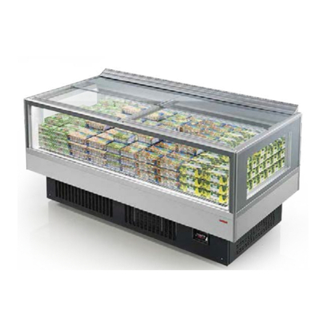
Arneg BERGEN 2 BT/TN GI R290 Direction for Installation and Use
Hussmann
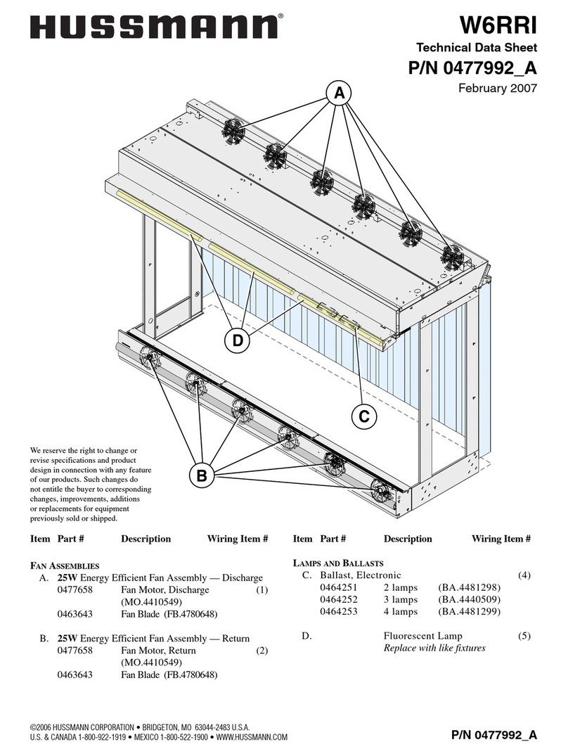
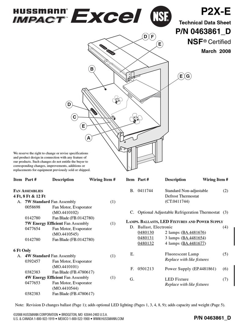
Hussmann Impact Excel P2X-E Technical data sheet

Hussmann
Hussmann EcoVision EZ Door Upgrade Installation & operation manual
Hoshizaki
Hoshizaki KD-90A parts list
Hussmann
Hussmann Impact Excel M3X-E Technical data sheet
