Hillphoenix OHMA-NRG User manual

SELF-CONTAINED MERCHANDISER
INSTALLATION & OPERATIONS MANUAL
To ensure proper functionality and optimum performance, it is STRONGLY recommended that Hillphoenix display cases be installed/
serviced by qualified technicians who have experience working with commercial refrigerated display merchandisers and storage cabinets.
For a list of Hillphoenix-authorized installation/service contractors, please visit our Web site at www.Hillphoenix.com.
O HMA - N RG
OHMAK-NRG
General Information ....................................... 2
Case Installation ............................................. 3
Case Connections .......................................... 4
Pre-Power Checklist ........................................ 5
Airow, Defrost & Temp Control ................... 6
Case Maintenance .......................................... 7
Appendix ......................................................... 8
Table of Contents
COMPONENT
C
L
A
S
S
I
F
I
E
D
EPH
COMPONENT
•P111801H

Copyright © 2018 by Hillphoenix
All rights reserved. No part of this document may reproduced or transmitted in any form or by any means - i.e., electronic
or mechanical, including photocopying, recording or any other information storage and retrieval system - without express
written permission from Hillphoenix.
REVISION HISTORY
ii
VERSION 2 (09/18)
•Updated data
VERSION 1 (05/18)
• new manual format
VERSION 1 (05/18)
• new manual format
•P111801H
VERSION 3 (11/18)
•Updated to add OHMAK-NRG
IMPORTANT NOTICES
LIABILITY NOTICE
For Cases with Shelf Lighting Systems
Hillphoenix does NOT design any of its shelf lighting sys-
tems or any of its display cases with shelf lighting systems
for direct or indirect exposure to water or other liquids. The
use of a misting system or water hose on a display case
with a shelf lighting system, resulting in the direct or indirect
exposure of the lighting system to water, can lead to a num-
ber of serious issues (including, without limitation, electri-
cal failures, re, electric shock, and mold) in turn resulting
in personal injury, death, sickness, and/or serious property
damage (including, without limitation, to the display itself,
to the location where the display is situated [e.g., store]
DANGER!
Indicates an immediate threat of death or
serious injury if all instructions are not fol-
lowed carefully.
CAUTION!
Indicates the potential threat of death or
serious injury if all instructions are not fol-
lowed carefully.
ATTENTION!
Indicates an important point of information
that is key to ensuring that case equip-
ment functions properly.
SERVICE NOTICE
To ensure proper functionality and optimum performance,
it is strongly recommended that Hillphoenix display cases
be installed/serviced by qualied technicians who have ex-
perience working with commercial refrigerated display mer-
chandisers and storage cabinets. For a list of Hillphoenix-
authorized installation/service contractors, please visit our
Web site at www.hillphoenix.com.
PRECAUTIONARY NOTICES
At Hillphoenix®, the safety of our customers and employ-
ees, as well as the ongoing performance of our products,
are top priorities. To that end, we call out important mes-
sages in all Hillphoenix installation and operations hand-
books with an accompanying alert symbol paired with the
words "DANGER!", "WARNING!", or "ATTENTION!". All
of these important messages will inform you of potential
haz-ards and dangers to personal safety and health - as
well as risks of case damage - if the instructions are not
carefully followed.
and to any surrounding property). DO NOT use misting
systems, water hoses or other devices that spray liquids
in Hillphoenix display cases with lighted shelves.
If a misting system or water hose is installed or used on a
display case with a shelf lighting system, then Hillphoenix
shall not be subject to any obligations or liabilities
(whether arising out of breach of contract, warranty, tort
[including negligence], strict liability or other theories of
law) directly or indirectly resulting from, arising out of or
related to such installation or use, including, without
limitation, any per-sonal injury, death or property
damage resulting from an electrical failure, fire, electric
shock, or mold.
P079211M, REVO
WARNING: UNDER NO CIRCUMSTANCES should
any component be replaced or added without
consulting Hillphoenix Field Service Engineering.
Utilizing im-proper components may result in serious
injury to per-sons or damage to the system.
iii
•P111801H

Thank you for choosing Hillphoenix for your food merchandising needs. This handbook contains important technical
information and will assist you with the installation and operation of your new Hillphoenix display cases. By closely fol-
lowing the instructions, you can expect peak performance; attractive fit and finish; and long case life.
We are always interested in your suggestions for improvements (e.g. case design, technical documents, etc.). Please feel
free to contact our Marketing Services group at the toll-free number listed below. Thank you for choosing Hillphoenix, and
we wish you the very best in outstanding food merchandising.
CASE DESCRIPTION
This manual covers OHMA self-contained merchandiser
(for operational data and case dimensions, see Appendix
A).
STORE CONDITIONS
Hillphoenix cases are designed to operate in an air-
conditioned store that maintains a 75°F (24°C) store tem-
perature and 55% (max) relative humidity (CRMA
condi-tions). Case operation will be adversely affected by
expo-sure to excessively high ambient temperatures
and/or humidity.
REFRIGERATION SYSTEM OPERATION
Air-cooled condensing units require adequate
ventilation for efficient performance.
RECEIVING CASES
Examine fixtures carefully and in the event of shipping
damage and/or shortages, please contact the Service
Parts Department at 1-800-283-1109.
CASE DAMAGE
Claims for obvious damage must be 1) noted on either the
freight bill or the express receipt and 2) signed by the car-
rier's agent; otherwise, the carrier may refuse the claim. If
damage becomes apparent after the equipment is
unpacked, retain all packing materials and submit a
written request to the carrier for inspection within 14
days of receipt of the equipment.
LOST/MISSING ITEMS
Equipment has been carefully inspected to insure the
high-est level of quality. Any claim for lost/missing items
must be made to Hillphoenix within 48 hours of receipt of
the equipment.
SERVICE & TECHNICAL SUPPORT
For service or technical questions regarding display cases,
please contact our Case Division Customer Service
Department at the toll-free number listed below. For ques-
tions regarding our refrigeration systems or electrical distri-
bution centers, please contact our Systems Division
Customer Service Department at 1-770-388-0706.
PARTS ORDERING
If you need to contact Hillphoenix regarding specific
fixtures/parts, call 1-800-283-1109 and ask for a Service
Parts Representative. Provide the following information
about the part you are ordering:
•Model number and serial number* of the case for which
the part is intended.
•Length of the part (if applicable).
•Color of part (if painted) or color of polymer part.
•Whether part is for left- or right-hand application.
•Quantity
*Serial plate is located inside the case on the top-left side.
If the parts are to be returned for credit, ask the Parts
Department to furnish you with a Return Material
Authorization Number.
Hillphoenix
1925 Ruffin Mill Rd.
Colonial Heights, VA 23834
Mon.-Fri. (8 a.m to 5 p.m EST
Tel: 1-800-283-1109
Fax: 804-526-7450
Web site:
www.Hillphoenix.com
GENERAL INFORMATION
ATTENTION!
Installation of 3rd-party materials may
result in diminished case performance.
2
•P111801H
CASE INSTALLATION
MOVING CASES
Hillphoenix display cases are generally shipped to
stores with casters installed on the base frame. The
casters make the job of moving cases easier for
everyone involved in the shipping and installation
process, as well as reducing the chance of damage
from raising and lowering cases with ”J” bars to
place them on dollies, skates or rollers. In most
situations, one or two persons can easily move the
case into position.
When the cases arrive at the store, simply roll them on to
the store floor to the proper staging area. Occasionally,
cases are shipped with skid boards attached to help with
stabilization. In these instances, the casters should be at-
tached after the case is removed from the truck.
Removing the casters is an easy process. Simply flatten
and remove the cotter pins that are holding the casters in
place (see Fig. 1). Then lift the case with a “J” bar and
slide the caster assemblies out. The dismantled casters
can now be discarded.
FLOOR PREP
1. Ask the general contractor if there have been changes
in the building dimensions since the print you are using
was issued. Also, ask for the points of reference from
which you should take dimensions to locate the cases.
2. Using chalk lines or a laser transit, mark the oor
where the cases are to be located for the entire lineup.
The lines should coincide with the outside edges of the
base frame.
3. Leveling is necessary to ensure proper case alignment
and to avoid potential damage. Locate the highest
point on the positioning line as a reference for deter-
mining the proper height of the shim-pack levelers. A
laser transit is recommended for precision and requires
just one person.
4. Locate the position of the base frame and spot properly
leveled shim packs at the appropriate locations.
LINE-UP & INSTALLATION
1. Remove anything from the cases that may interfere
with case joining (eg. shipping braces).
2. Roll the rst case into position. Using a “J” bar , raise
the end of the case (under cross support), remove the
casters, and place the base frame on the shim packs.
Repeat on the other end of the case.
3. Once the base frame is properly placed on the shim
packs, check the vertical level by placing a bubble level
plumb to the rear edge of the case; then add/remove
shim levels as needed. To check the horizontal level,
repeat this process after placing the bubble level on
the rear sill.
4. If seismic brackets were ordered, see Appendix F for
detailed installation instructions.
TRIM OUT
Attach the front panel to the baseframe using the screws
provided.
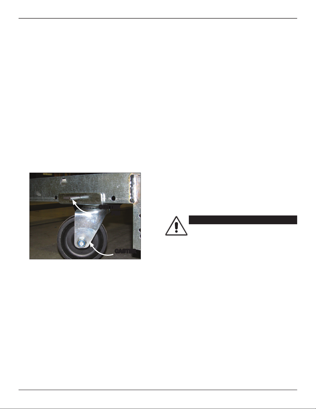
Fig. 1 Removing the casters is an easy process. Simply
flatten and remove the cotter pins that are holding the
casters in place. Then lift the case with a “J” bar and
slide the caster assemblies out. The dismantled casters
can now be discarded.
CASTER
COTTER
PIN
CAUTION!
Be certain that your hands and feet are
out of the way before lowering the case
after the removal of the casters. Failure
to do so may result in serious injury.
3
•P111801H

CASE CONNECTIONS
REFRIGERATION
Refrigeration components for OHMA are easily accessible
in the tank and beneath the case.
The expansion valve and suction line 1/4” access valve
are both located on the front-left side of the tank. These
components may be reached removing the front panel and
pulling out the sliding component tray that houses all of
the internal case components. For a detailed illustration of
internal case components, see Appendix H.
PLUMBING
The “P” trap assembly – attached to the case at the fac-
tory so no assembly is required – directs the case drainage
to the evaporative drain pan (Fig. 2). The case drain is
located front-and-center in the case for convenient access
– simply remove the front panel and slide out the compo-
nent tray. Should any future maintenance issues arise,
it is important to note the outlet is specially molded with
PVC material and the “P” trap is constructed of PVC. Care
should be given to make certain that all connections are
water tight and are sealed with appropriate PVC primer and
PVC cement.
Be certain that the case is properly leveled to ensure prop-
er drainage.
ELECTRICAL
OHMA cases come pre-wired with a NEMA L14-30P
twist-lock plug (250 volt, 4-prong).
NEMA L14-30P
PLUG
(TWIST LOCK)
A Dixell XR04CX digital controller is provided
for case operation and programming. The
controllers are lo-cated inside the electrical junction box
and are utilized ac-cording to your temperature
preference. For detailed in-structions for the Dixell
controller, see Appendix E.
"P" TRAP
Fig. 2 Drain "P" trap
ATTENTION!
Be certain to clear the case of any loose
packaging or case materials before ener-
gizing the case. Failure to do so may re-
sult in case damage or malfunction.
ATTENTION!
Be certain that all piping and electrical
connections comply with local codes.
4
•P111801H

PRE-POWER CHECKLIST
Before powering-up the case, be certain that all of the steps listed below
have been completed to ensure proper case functionality, safety and com-
pliance with warranty terms.
Have you thoroughly examined the case for shipping damage? (see
pg. 2)
Have you removed and discarded the casters? (see pg. 3)
Have you checked the vertical plumb of the case? The horizontal
level? (see pg. 3)
Have you removed any loose packaging or materials? (see pg. 4)
5
•P111801H
AIRFLOW, DEFROST & TEMP CONTROL
AIR FLOW & PRODUCT LOAD
Cases have been designed to provide maximum product
capacity within the refrigerated air envelope. Please keep
products within the load limit line shown on the diagram
below (Fig. 4).
It is important that you do not overload the food product dis-
play so that it impinges on the air ow pattern. Overloading
will cause malfunction and the loss of proper temperature
levels, particularly when discharge and return air sections
are covered.
DEFROST & TEMPERATURE CONTROLS
OHMA cases are equipped with timed-off defrost. When
timed-off defrost is used, the refrigeration cycle is turned off
by the case controls for a specified amount of time; there-
fore, there are generally no active defrost components uti-
lized.
The discharge air probe monitors the temperature of the
discharge air and may be used as the defrost termination
sensor. The probe can generally be found behind the rear
baffle, in the upper baffle, or in front of the honeycomb.
For more detailed information on suggested defrost times
and settings, see Appendix A. Further adjustment may be
required depending on store conditions.
Fig. 5 Obtain pressure and temperature readings
SUCTION
LINE TEMP
READING
SUCTION
PRESSURE
READING
TXV
BULB
DETERMINING SUPERHEAT
To identify proper superheat settings, complete the follow-
ing:
1. Obtain suction pressure from access port; obtain suc-
tion line temperature from area near TXV bulb at the
outlet of evaporator coil (Fig. 5).
2. Using the suction pressure reading, convert pressure
to temperature using temperature pressure chart (see
Appendix D).
3. Subtract the converted temperature reading from the
actual temperature reading for superheat setting.
Fig. 4 Airflow
RETURN
AIR
DISCHARGE
AIR
AIR FLOW
LOAD
LIMIT
6
•P111801H

CASE MAINTENANCE
CASE CLEANING
Cases are designed to facilitate cleaning. All surfaces
pitch to a deep-drawn drain trough that angles toward the
front-center of the case where the waste outlet is located
for easy access.
The coil is covered to prevent waste fluids from entering,
but it is easily accessible for cleaning: remove the front
panel, slide out the case component tray, remove the coil-
cover fasteners, then lift and remove the coil cover. With
the coil cover removed, be certain to exercise extreme cau-
tion when working in the case - the coil has many sharp
edges that can result in serious injuries. When cleaning is
complete, be certain that both the plenum and coil cover
are properly closed in order to avoid air leaks.
CLEANING PROCEDURES
A periodic cleaning schedule should be established to
maintain proper sanitation, insure maximum operating ef-
ficiency, and avoid the corrosive action of food fluids on
metal parts that are left on for long periods of time. We
recommend cleaning once a week.
•To avoid shock hazard, be sure all electrical power is
turned off before cleaning. In some installations, more
than one disconnect switch may have to be turned off
to completely de-energize the case.
•Check waste outlet to insure it is not clogged before
starting the cleaning process and avoid introducing
water faster than the case drain can carry it away.
•Avoid spraying cleaning solutions directly on electrical
connections.
•Allow cases to be turned off long enough to clean any
frost or ice from coil and pans.
•Use mild detergent and warm water. When necessary,
water and baking soda solution will help remove case
odors. Avoid abrasive scouring powders or pads.
•Clean underneath the case with a broom and a long
handled mop.
•Use warm water and a disinfecting cleaning solution
when cleaning underneath the cases.
DANGER!
Always disconnect power to case when
servicing or cleaning. Failure to do so
may result in serious injury or death.
CAUTION!
Exercise extreme caution when working
in a case with the coil cover removed.
The coil contains many sharp edges that
can result in severe cuts to the hands and
arms.
ATTENTION!
Power cord must be pushed back through
the plenum opening before removing the
fan basket. Failure to do so may result in
damage to the power cord.
7
•P111801H

a1 - a2 ................................................................................................................. ohma operational Data & Case Dimensions
B1 - B2 ................................................................................................................................................................... eleCtriCal Wiring
C1 ........................................................................................................................................................................................... set points
D1 ................................................................................................................................ sporlan pressure-temperature Chart
e1 .............................................................................................................................................................. DiXell Case Controller
f1 - f5 ............................................................................................................................................. seismiC BraCKet installation
g1 ................................................................................................................................................................... peg hooK information
h1 ........................................................................................................................................... internal Case Component laYout
APPENDIX
8
•P111801H

Rev #Rev Date: Revision Description:
ALL MEASUREMENTS ARE TAKEN PER
ASHRAE-72-2005 SPECIFICATIONS. Hillphoenix
REFRIGERATED DISPLAY CASES FOR SALE IN THE
UNITED STATES MEET OR EXCEED DEPARTMENT OF
ENERGY 2017 REQUIREMENTS.
COMPONENT
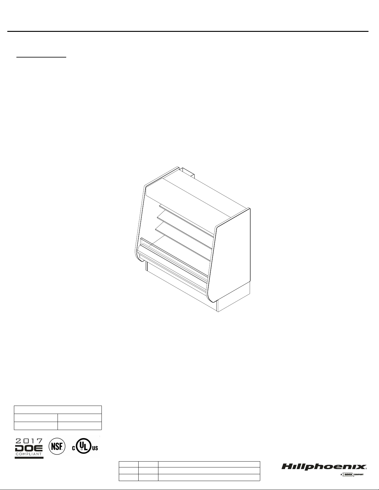
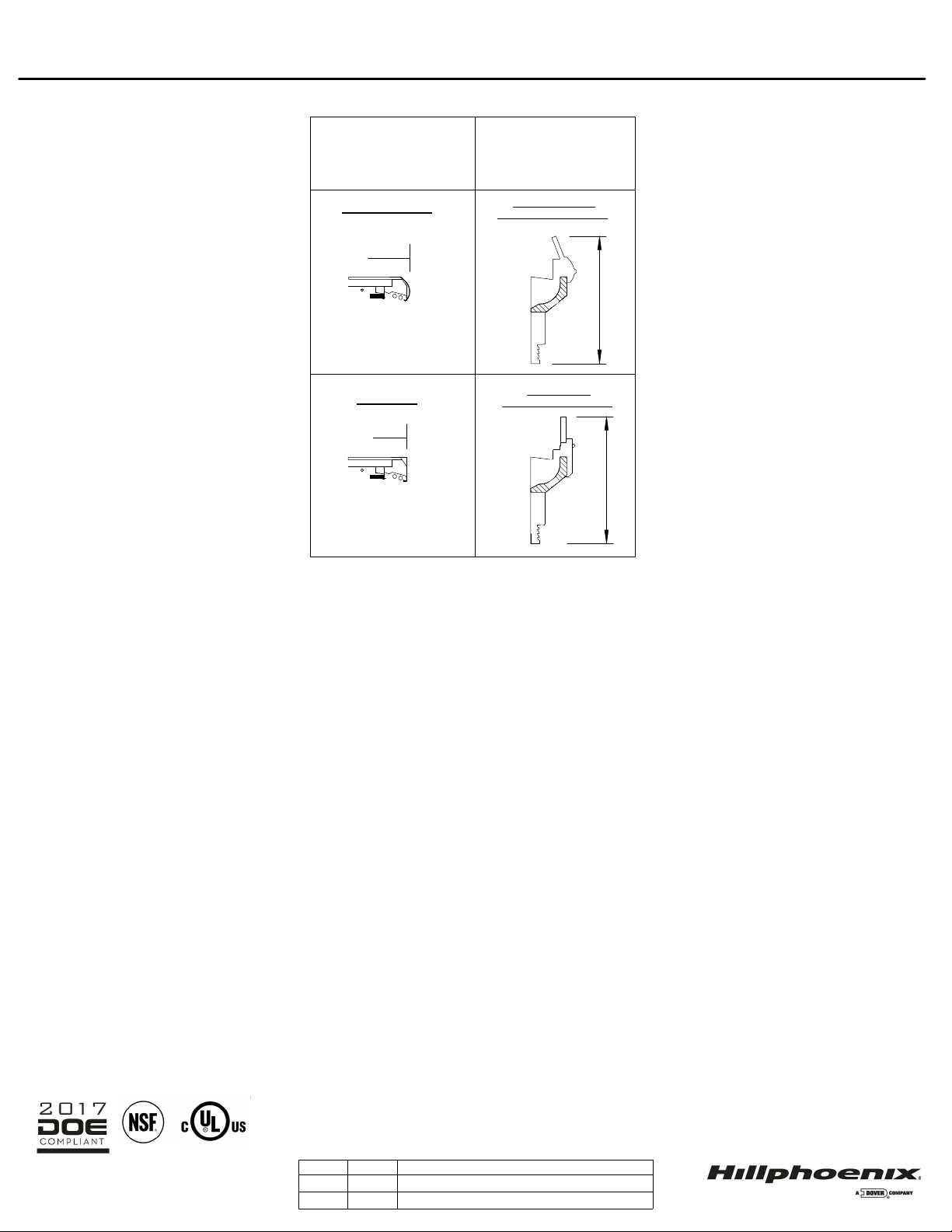
OHMA-NRG High Multi-Deck Self-Contained Merchandiser
6' (Meat)
OHMA-NRG
110-27-17 DOE 2017
REFERENCE NOTES FOR ENGINEERING DATA
REFERENCE NOTES FOR CROSS SECTIONS
* : STUB-UP AREA
** : RECOMMENDED STUP-UP CENTERLINE FOR ELECTRICAL AND HUB DRAINS
• Front sill height and overall case height varies with base frame height
•Ends add approximately 1" to case height, 1/2" to the back & 1" to the front
• Wiring to the top adds approximately 4" to case height
•A 2" minimum air gap is required between the rear of the case and a wall
•Back panels add approximately 1" to the rear of the case
• Available shelf sizes: 18", 20" & 22"
• Dashed line signify area inside base rail behind kick plate
• Casters add approximately 2 1/4" to case height
• Listed discharge air velocity represents the average velocity at the peak of defrost.
• Temperature and defrost settings listed below are recommended start-up settings. Final operational settings
may need to be adjusted for the store conditions in which the case operates.
•LED lights only.
• Maximum of 3 rows of Standard Output LED lighted shelves.
• 3rd row or nose lights are not available.
• 2 rows of standard or 1 row of cornice high output LED lights only.
• 6" thermopane front required.
•P111801H
Rev #Rev Date: Revision Description:
ALL MEASUREMENTS ARE TAKEN PER
ASHRAE-72-2005 SPECIFICATIONS. Hillphoenix
REFRIGERATED DISPLAY CASES FOR SALE IN THE
UNITED STATES MEET OR EXCEED DEPARTMENT OF
ENERGY 2017 REQUIREMENTS.
COMPONENT
OHMA-NRG High Multi-Deck Self-Contained Merchandiser
6' (Meat)
OHMA-NRG
110-27-17 DOE 2017
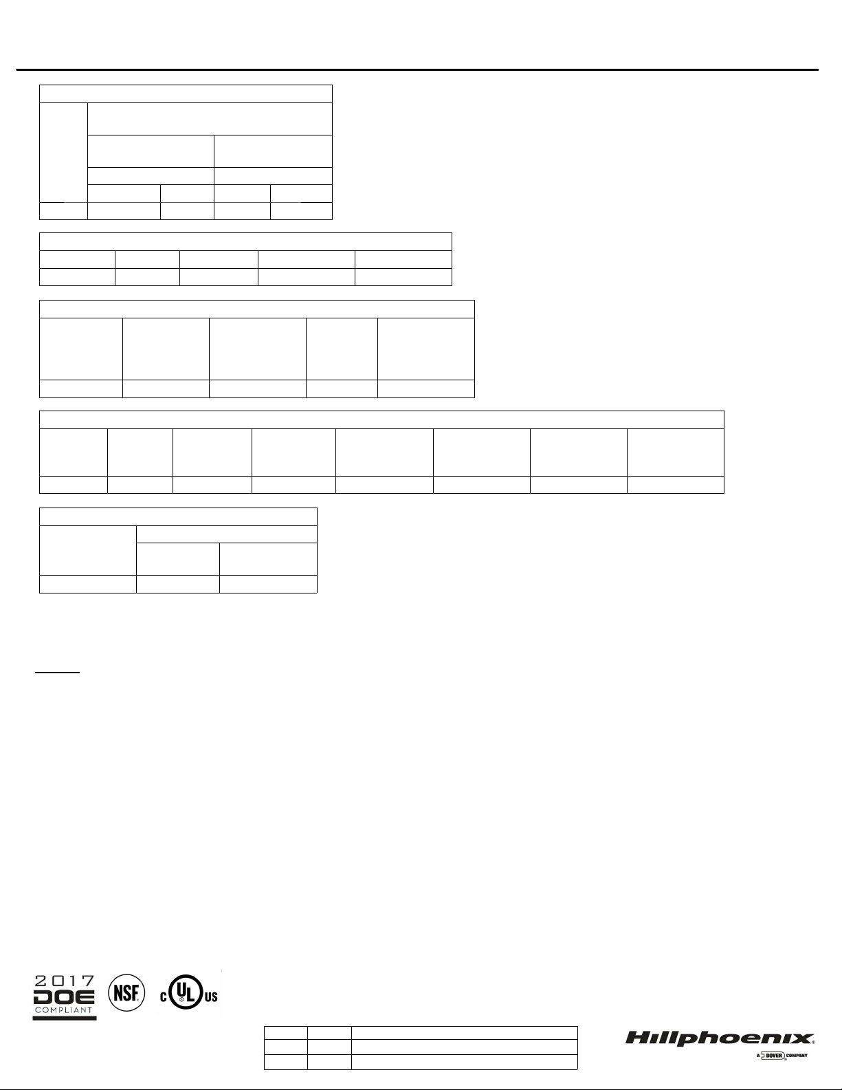
SYSTEM REQUIREMENTS
Volts Phase Frequency (Hz) Plug Style Cord Length
208 1 60 NEMA L14-30P 120"
LIGHTING DATA
Lights
Per Row
Light
Length
Clearvoyant v4 LED Lighting
(Per Lifght Row)
Standard Power
(Cornice or Shelf)
High Power
(Cornice Only)
120 Volts 120 Volts
Amps Watts Amps Watts
2 3' 0.08 9.4 0.20 23.8
GUIDELINES AND CONTROL SETTINGS
24 hour Energy
Usage
Suction Pressure @ Case
Outlet (psig).
Superheat Set Point
@ Bulb
Discharge
Air
Discharge
Air Velocity
47.6 (kWh) 52-54 6-8 °F 30.0 °F 210 FPM
CONDENSING UNIT DATA
Volts Phase
Frequency
(Hz) Horsepower
Running Load
Amps (RLA)
(Amps)
Locked Rotor
Amps (LRA)
(Amps) Refrigerant
Lbs. of
Refrigerant
208 1 60 1 1/4 9.2 54.0 R404A 5.5
DEFROST CONTROLS
Defrosts
Per Day
Timed-Off Defrost
Fail-Safe
(Min)
Termination
Temp
6 30 (Min) 42 °F
•P111801H
42 11/16" [108.4 cm]
28 5/8" [72.7 cm]
18 in
20 in
22 in
PLENUM
COIL
48 3/8" [122.8 cm]
79 1/2" [201.9 cm]
15" [38.1 cm]
32 1/2" [82.6 cm]
32 1/4" [81.9 cm]
LOAD LIMIT
LINE
6" THERMOPANE
GLASS WITH
FLAT FRONT
9" MIRROR
37 1/16" [94.2 cm]
34 1/4" [87.0 cm]
41 3/4" [106.0 cm]
42 11/16" [108.4 cm]
72" [182.9 cm]
ELECTRICAL
JUNCTION BOX
1 1/2" [3.8 cm] {END}
CONDENSING
UNIT
DRAIN PAN
Front of case
32 1/2" [82.5 cm]
KICKPLATE
LOCATION
DRAIN
EGRESS
REFRIGERATION
EGRESS
Rev #Rev Date: Revision Description:
ALL MEASUREMENTS ARE TAKEN PER ASHRAE-72-
2005 SPECIFICATIONS. Hillphoenix REFRIGERATED
DISPLAY CASES FOR SALE IN THE UNITED STATES
MEET OR EXCEED DEPARTMENT OF ENERGY 2017
REQUIREMENTS.
COMPONENT
OHMA-NRG High Multi-Deck Self-Contained Merchandiser
6' (Meat)
OHMA 6'
110-27-17 DOE 2017
•P111801H
Rev
#
Rev Date:
Revision Description:
A
LL MEASUREMENTS ARE TAKEN PER
A
SHRAE-72-2005 SPECIFICATIONS. HILLPHOENIX
REFRIGERATED DISPLAY CASES FOR SALE IN THE
UNITED STATES MEET OR EXCEED DEPARTMENT
OF ENERGY 2017 REQUIREMENTS.
COMPONENT
OHMAK-NRG High Multi-Deck Self-Contained Merchandiser
6' (Meat)
OHMAK-NRG
28-7-18 NEW STANDARDS
39-19-18 DATA UPDATE
GENERAL NOTES
•" ---" indicates that the feature is not an option for this case model and/or the data is not yet available.
• LED lights only.
• Maximum of 3 rows of standard output LED lighted shelves.
• Nose lights are not available.
SHIPPING WEIGHT
Case Weight
OHMAK-NRG ---
Rev
#
Rev Date: Revision Description:
A
LL MEASUREMENTS ARE TAKEN PER
A
SHRAE-72-2005 SPECIFICATIONS. HILLPHOENIX
REFRIGERATED DISPLAY CASES FOR SALE IN THE
UNITED STATES MEET OR EXCEED DEPARTMENT
OF ENERGY 2017 REQUIREMENTS.
COMPONENT
OHMAK-NRG High Multi-Deck Self-Contained Merchandiser
6' (Meat)
OHMAK-NRG
28-7-18 NEW STANDARDS
39-19-18 DATA UPDATE
NOTES
• "---" indicates that the feature is not an option for this case model and/or the data is not yet available.
• Listed discharge air velocity represents the average velocity immediately after defrost.
• Temperature and defrost settings listed below are recommended start-up settings. Final operational settings
may need to be adjusted for the store conditions in which the case operates.
LIGHTING DATA
Lights
per row
Clearvoyant v4 LED Lighting
(Per Light Row)
Standard Power
(Cornice or Shelf)
High Power
(Cornice Only)
120 Volts 120 Volts
Amps Watts Amps Watts
2 0.08 9.4 0.20 23.8
GUIDELINES AND CONTROL SETTINGS
24hr Energy
Usage (kWh)
Suction
Pressure @
Case Outlet
(psig)
Superheat Set
Point @ Bulb
(°F)
Discharge
Air (°F)
Discharge Air
Velocity (FPM)
47.6 52-54 6 - 8 30.0 210
DEFROST CONTROLS
Defrosts Per
Day
Timed-Off Defrost
Fail-Safe
(Min)
Termination
Temp (F)
63047
SYSTEM REQUIREMENT
Volts Phase Frequency Plug Style Cord Length
208 1 60 NEMA L14-20P 120"
CONDENSING UNIT DATA
Volts Phase Frequency Horsepower
Running Load
Amps (RLA)
(Amps)
Locked Rotor
Amps (LRA)
(Amps) Refrigerant
Lbs. of
Refrigerant
208 1 60 1 1/4 9.2 54.0 R404A 5.5
Rev
#
Rev Date: Revision Description:
A
LL MEASUREMENTS ARE TAKEN PER
A
SHRAE-72-2005 SPECIFICATIONS. HILLPHOENIX
REFRIGERATED DISPLAY CASES FOR SALE IN THE
UNITED STATES MEET OR EXCEED DEPARTMENT
OF ENERGY 2017 REQUIREMENTS.
COMPONENT
OHMAK-NRG High Multi-Deck Self-Contained Merchandiser
6' (Meat)
OHMAK-NRG
112-1-17 DOE 2017
28-7-18 NEW STANDARDS
OHMAK-NRG (Meal Kit) Case Configuration
Case Model
OHMAK-NRG (Meal Kit) Base
Model
OHMAK-NRG (Meal Kit)
Configured Options
Length 6' n/a
Case Use Meal Kits n/a
Base Frame 15" n/a
Exterior Color CC Stainless
LH End Type Solid Square
RH End Type Solid Square
End Skins Interior: SA, Exterior: CC Painted/Painted
Stainless/Stainless
End Trim Type/Color Black PVC Stainless
Front Type Flat Front Origin 2
Front Panel Type Contour Flat
ColorBand Panel Finish CC Stainless
Sill Cap Finish Stainless Painted
Cornice Type Flat Curved
Cornice Finish Painted Stainless
Tank Finish Painted Aluminum Stainless
Interior Color CC White Stainless
Baffle Finish CC White Stainless
Frame Finish CC White
Flue Panel Finish CC White Stainless
Deck Pan Type Plastic Metal
Deck Pan Finish/Color Black White Galvanized
Painted Stainless
Mirror Size 9.75"
Wire Rack Type Telescopic Fixed Front Lip Height
Wire Rack Finish Black White Stainless
Shelf Depth 18", 20", 22"
PTM Type AL PVC
LED Type Standard High
LED Color 30k 35k 40k
Cornice Lighting Type 2 Row 1 Row
Refrigerant R404a
Piping Top
Defrost Off Cycle
Fans (HE, STD) ECM
Refrigeration Accessories None Optional: Solenoid,
Thermostat
Thermometer Std
Probe None Optional: Electronic
Sensor
Special Instructions Shiploose Condensing Unit +
Drain Pump + Pan
Optional: Fully Installed
Condensing Unit +
Pump + Pan
CORNICE
OPTIONS
FRONT
OPTIONS
CURVED CORNICE
ORIGIN 2 FRONT
WITH 6" THERMOPANE
FLAT FRONT FLAT FRONT
WITH 6" THERMOPANE
37 1/8" [94.2 cm] 37 1/8" [94.4 cm]
TANK
TANK
Rev
#
Rev Date: Revision Description:
A
LL MEASUREMENTS ARE TAKEN PER
A
SHRAE-72-2005 SPECIFICATIONS. HILLPHOENIX
REFRIGERATED DISPLAY CASES FOR SALE IN THE
UNITED STATES MEET OR EXCEED DEPARTMENT
OF ENERGY 2017 REQUIREMENTS.
COMPONENT
OHMAK-NRG High Multi-Deck Self-Contained Merchandiser
6' (Meat)
OHMAK-NRG
28-7-18 NEW STANDARDS
39-19-18 DATA UPDATE
34 1/4"
33 5/8"

42 11/16" [108.4 cm]
28 5/8" [72.7 cm]
18 in
20 in
22 in
28 3/8" [72.1 cm]
CONDENSING UNIT
PLENUM
COIL
46 7/8" [119.1 cm] INTERIOR HEIGHT
79 1/2" [201.9 cm] CASE HEIGHT
15" [38.1 cm]
32 1/2" [82.6 cm]
36 7/8" [93.7 cm]
41 7/8" [106.4 cm] VISUAL DISPLAY
32 1/4" [81.9 cm]
LOAD LIMIT
31 1/8" [79.0 cm]
6" THERMOPANE
GLASS WITH
FLAT FRONT
9" MIRROR
81 3/4" [207.6 cm] SHIPPING HEIGHT
43 1/4" [109.9 cm]
72" [182.9 cm]
32 1/2" [82.6 cm]
26 1/8" [66.4 cm]
ELECTRICAL
JUNCTION BOX
DRAIN PAN
CHIMNEY FOR
HOT AIR EXHAUST
32 3/8" [82.2 cm]**
1 1/2" [3.8 cm] {END}
CONDENSING
UNIT
1 1/2" PVC DRAIN
CONNECTION
27 7/16" [69.6 cm]
Rev
#
Rev Date: Revision Description:
A
LL MEASUREMENTS ARE TAKEN PER
A
SHRAE-72-2005 SPECIFICATIONS. HILLPHOENIX
REFRIGERATED DISPLAY CASES FOR SALE IN THE
UNITED STATES MEET OR EXCEED DEPARTMENT
OF ENERGY 2017 REQUIREMENTS.
COMPONENT
OHMAK-NRG High Multi-Deck Self-Contained Merchandiser
6' (Meat)
OHMAK-NRG
28-7-18 NEW STANDARDS
39-19-18 DATA UPDATE

ATTENTION
ELECTRICIAN
:FOR SAFETY AND CODE
COMPLIANCE GROUND
FIXTURE AT TIME OF
INSTALLATION
:CAUTION
RISK OF ELECTRIC
SHOCK. MORE THAN ONE
POWER-SUPPLY.
DISCONNECT
ALL POWER-SUPPLIES
BEFORE SERVICING.
P901598E - R5
WIRE ID
Wiring iDentifiCation
B1
•P111801H

Wiring Diagram
B2
•P111801H
This manual suits for next models
1
Table of contents
Other Hillphoenix Merchandiser manuals


Popular Merchandiser manuals by other brands


Hussmann
Hussmann SLGV Technical data sheet

Silver King
Silver King SKCTMDI Technical manual and replacement parts list

Hussmann
Hussmann IMPACT LW Technical data sheet

Hussmann
Hussmann Specialty ProductsCR3FO Technical data sheet

RCm
RCm RCM-77-N14NF instruction manual

Hussmann
Hussmann ESBD Technical data sheet