Hillphoenix VRBH User manual

VRB VRBH
VNRB VNRBH VNRBS
P092878A
V1.00
09/19
REACH-IN MERCHANDISER
INSTALLATION & OPERATIONS MANUAL
General Information ............................................... 4
Installation ..........................................................5-7
Case Connections ...............................................8-9
Pre-Power Checklist ............................................10
Airflow & Defrosts ................................................11
Fan Maintenance & Case Cleaning ....................12
Parts Ordering ......................................................13
Appendices
Table of Contents
To ensure proper functionality and optimum performance, it is STRONGLY recommended that Hillphoenix specialty cases be installed/serviced by qualified tech-
nicians who have experience working with commercial refrigerated display merchandisers and storage cabinets. For a list of Hillphoenix-authorized installation/
service contractors, please visit our website at www.hillphoenix.com.

ii

iii
LIABILITY NOTICE
For Cases with Shelf Lighting Systems
Hillphoenix does NOT design any of its shelf lighting systems or any of its display cases with shelf lighting
systems for direct or indirect exposure to water or other liquids. The use of a misting system or water hose
on a display case with a shelf lighting system, resulting in the direct or indirect exposure of the lighting
system to water, can lead to a number of serious issues (including, without limitation, electrical failures,
fire, electric shock, and mold) in turn resulting in personal injury, death, sickness, and/or serious proper-
ty damage (including, without limitation, to the display itself, to the location where the display is situated
[e.g., store] and to any surrounding property). DO NOT use misting systems, water hoses or other devices
that spray liquids in Hillphoenix display cases with lighted shelves.
If a misting system or water hose is installed or used on a display case with a shelf lighting system, then
Hillphoenix shall not be subject to any obligations or liabilities (whether arising out of breach of contract,
warranty, tort [including negligence], strict liability or other theories of law) directly or indirectly resulting
from, arising out of or related to such installation or use, including, without limitation, any personal injury,
death or property damage resulting from an electrical failure, fire, electric shock, or mold.
P079211M, REVO

iv
Important
DANGER
▲
Indicates an immediate threat of death or
serious injury if all instructions are not followed
carefully.
At Hillphoenix®, the safety of our customers and employees, as well as the ongo-
ing performance of our products, are top priorities. To that end, we include import-
ant warning messages in all Hillphoenix installation and operations handbooks,
accompanied by an alert symbol paired with the word "DANGER", "WARNING", or
"CAUTION".
All warning messages will inform you of the potential hazard; how to reduce the
risk of case damage, personal injury or death; and what may happen if the in-
structions are not properly followed.
WARNING
Indicates a potential threat of death or serious
injury if all instructions are not followed careful-
ly.
▲
CAUTION
Indicates that failure to properly follow instruc-
tions may result in case damage.
▲
!
!
!

v
Revision History
• new manual format_9/19

4
Thank you for choosing Hillphoenix for your food merchandising needs. This handbook contains important technical infor-
mation and will assist you with the installation and operation of your new Hillphoenix specialty cases. By closely following
the instructions, you can expect peak performance; attractive fit and finish; and long case life.
We are always interested in your suggestions for improvements (e.g. case design, technical documents, etc.). Please feel
free to contact our Marketing Services group at the number listed below. Thank you for choosing Hillphoenix, and we wish
you the very best in outstanding food merchandising.
CASE DESCRIPTION
This manual specifically covers the VNRB, VNRBS, VNRBH,
VRB, and VRBH.
STORE CONDITIONS
Hillphoenix cases are designed to operate in an air-condi-
tioned store that maintains a 75°F (24°C) store temperature
and 55% (max) relative humidity (ASHRAE conditions). Case
operation will be adversely affected by exposure to excessively
high ambient temperatures and/or humidity.
REFRIGERATION SYSTEM OPERATION
Air-cooled condensing units require adequate ventilation for
efficient performance. Machine-room temperatures must be
maintained at a minimum of 65°F in winter and a maximum
of 95°F in summer. Minimum condensing tem-peratures
should be no less than 70°F.
SHIPPING CASES
Transportation companies assume all liability from the time a
shipment is received by them until the time it is delivered to
the consumer. Our liability ceases at the time of shipment.
RECEIVING CASES
Examine fixtures carefully and in the event of shipping dam-
age and/or shortages, please contact the Service Parts
Department at the number listed below.
CASE DAMAGE
Claims for obvious damage must be 1) noted on either the
freight bill or the express receipt and 2) signed by the carrier's
agent; otherwise, the carrier may refuse the claim. If damage
becomes apparent after the equipment is unpacked, retain all
packing materials and submit a written request to the carrier
for inspection within 14 days of receipt of the equipment.
Failure to follow this procedure will result in refusal by the
carrier to honor any claims with a consequent loss to the
consumer.
If a UPS shipment has been damaged, retain the damaged
material, the carton and notify us at once. We will file a claim.
LOST/MISSING ITEMS
Equipment has been carefully inspected to insure the highest
level of quality. Any claim for lost/missing items must be
made to Hillphoenix within 48 hours of receipt of the equip-
ment. When making a claim please use the number listed
below.
SERVICE & TECHNICAL SUPPORT
For service or technical questions regarding display cases,
please contact our Case Division Customer Service
Department at the toll free number listed below. For questions
regarding our refrigeration systems or electrical distribution
centers, please contact our Systems Division Customer
Service Department at 1-770-388-0706.
CONTACTING THE FACTORY
If you need to contact Hillphoenix regarding a specific fixture,
be certain that you have both the case model number and
serial number (this information can be found on the data tag,
located on the top-left interior of the case). When you have
this information, call the toll-free number below and ask for a
Service Parts Representative.
GENERAL INFORMATION
Hillphoenix
1925 Ruffin Mill Rd
Colonial Heights, VA 23834
Mon.-Fri. (8 a.m. to 5 p.m.)
Tel: 1-800-283-1109/Fax: 804-526-7450
Website: www.hillphoenix.com

5
CASE INSTALLATION
FLOOR PREP
1. Ask the general contractor if your current copy of the
building dimensions are the most recently issued. Also,
ask for the points of reference from which you should
take dimensions to locate the cases.
2. Using chalk lines or a laser transit, mark the fl oor
where the cases are to be located for the entire lineup.
The lines should coincide with the outside edges of the
case feet.
3. Leveling is necessary to ensure proper case alignment
and to avoid potential case damage. Locate the high-
est point on the positioning lines as a reference for
determining the proper height of the shim-pack level-
ers. A laser transit is recommended for precision and
requires just one person.
4. Locate basehorse positions along the chalk lines. Spot
properly leveled shim packs at each basehorse loca-
tion.
LINE-UP & INSTALLATION
Single Case
1. Roll the case into position, leaving a minimum of 2" be-
tween the wall and back of case. Using a “J” bar, raise
the end of the case (under cross support), remove the
caster assembly (Fig. 1) and lower the basehorse on to
the shim packs. Repeat on the other end of the case.
2. Once the basehorse is properly placed on the shim
packs, check the vertical plumb of the case by placing
a bubble level on the shelf standard. Add/remove shim
packs as needed. For the horizontal level, repeat this
process after placing the bubble level on the front sill.
Multi-Case
1. Remove any shelves (discard the shelf clips) and/or
loose items (e.g. shipping braces, mirror assemblies,
etc) from the cases that may interfere with case join-
ing. Keep all loose items as they will be used later
in the installation process.
2. Remove the return air grill at the case joint. The grill
lifts out without fasteners and may be easily removed
to gain clear access to the case-to-case joining bolts.
3. Follow the single-case installation instructions for the
fi rst case, then position the next case in the line-up ap-
proximately 3’ away. Remove the casters on the end
that is closest to the fi rst case.
4. Apply the foam tape gasket (supplied) and a bead of
butyl or silicone sealant to the end of the fi rst case (Fig.
2). From the opposite end, push the second case to
a position that is approximately 6" from the fi rst case,
then remove the remaining casters and position case
on the shim packs.
CAUTION!
Be certain that your hands and feet are
out of the way before lowering the case
after the removal of the casters. Failure
to do so may result in serious injury.
Fig. 1 Removing the casters is an easy process. Simply flatten and
remove the cotter pins that are holding the casters in place. Then
lift the case with a “J” bar and slide the caster assemblies out. The
dismantled casters can now be discarded.
COTTER
COTTER
PIN
PIN
CASTER
CASTER
= bolt holes
X = foam tape gasket
O = butyl or silicone sealant
NOTE: It is recommended that
cases be bolted together in
the numbered order indicated
in the diagram.
1
2
5
4
Fig. 2 Bolt holes, foam tape gasket and sealant
3

6
CASE INSTALLATION
Fig. 5 Front panel joint trim
Fig. 3 Sealing the pipe chase
ACRYLIC
TAPE
PIPE
CHASE
TRIM OUT
1. Seal the case-to-case joints with caulk (supplied), then
apply acrylic tape (supplied) over the pipe-chase seam
(Fig. 3). The tape acts as a watershed preventing wa-
ter from settling in the case joint.
If non-insulated plexiglass partitions are included, see
Appendix * for installation instructions.
Re-install shelves (or peg hook assemblies if appli-
cable). Be aware that differing shelf confi gurations
will
affect energy consumption and case performance. If
peg hook assemblies are to be installed, see Appen-
dix ) for more information.
Install the front panel (Fig. 4). The front panel bottom
insert is a painted panel that ships loose with the case.
The panel is inserted upward under the door frame ex-
teriors and is supported without fasteners by setting
the panel on the tabs as shown.
Make any adjustments that are necessary to properly
align the front panels, then install the front panel trim
that is supplied (Fig. 5).
6. Inside the case, use the supplied sex bolts to close the
gap between the frames (Fig. 6). On the outside, run
a thin bead of caulk along the case-to-case seam, then
carefully push the T-Bar case frame joint trim into the
space between the frames (Fig. 7).
Fig. 4 Install front panel
FRONT PANEL
(TOP INSERT)
FRONT PANEL
(BOTTOM INSERT)
FRONT
FRONT
PANEL
PANEL
TRIM
TRIM
Fig. 6 Sex bolts for closing case frame gap
SEX BOLT
Loosen the cornice joint at case end (cornice screws
are located on top of the case). Be certain that cornice
joints and pins are properly aligned. Cases are now
ready to be joined.
Push the cases tightly together, then lightly bolt them
together through the holes that are provided (Fig. 2).
Tighten all the joining bolts until all margins are equal.
Be careful not to over tighten.
Repeat steps 3–6 of this sequence for all remaining
cases. Be certain to properly level all cases.
Install the seismic brackets (if included). See Appen-
dix + for installation instructions.

7
CASE INSTALLATION
Fig. 8 Attach kickplate with supplied screws
KICKPLATE
KICKPLATE
RETAINER
SCREWS
Fig. 7 T-Bar case frame joint trim seals case frame gap
T-BAR
T-BAR
CASE FRAME
CASE FRAME
JOINT
JOINT
FRAME
FRAME
GAP
GAP
7. Install the front kickplate (Fig. 8) to the kickplate re-
tainer as shown. Install the end kickplates with screws
provided and insert the plug buttons.
8. Install the case top fascia (if included). See Appendix
D for installation instructions.
9. Install electric display modules (if included). See Ap-
pendix E for installation instructions.
10. If the case is outfi tted with a factory-installed, snap-on
bumper track, install the snap-on track bumper onto
the track, up to 96 feet. For rigid bumper, cut for as
tight a fi t as possible–to allow for minor shrinkage fol-
lowing start-up–and install. For rolled bumper, Hill-
phoenix recommends leaving an additional 6 inches of
nose bumper at the ends to allow for shrinkage during
the fi rst 24–48 hours following case start-up (Fig. 9).
11. After suffi cient time has passed, cut away the excess
bumper for fi nal fi t and fi nish. Be certain to use an ap-
propriate cutting tool (tubing- or PVC-cutter) to ensure
a smooth cut.
Fig. 9 Leave 6 inches of extra bumper

8
CASE CONNECTIONS
ATTENTION!
If brazing is necessary, place wet rags
around the area to avoid tank damage.
REFRIGERATION
There are two refrigeration piping options for this case fam-
ily: standard and rear top-box. Standard piping penetration
is located at the front-right area of the case, fully visible in
front of the fan plenum. The rear-box top option consists of
piping enclosed in a foam box that exits at the back-right of
the case, near the top.
Expansion valve and other controls—located on the left-
hand side of the case—are accessed by lifting the two left-
hand deck pans (lifting the fan plenum is not required).
Before operating the case, be certain to remove the ship-
ping blocks (Fig. 10) that protect the refrigeration lines dur-
ing shipping. If it becomes necessary to penetrate the case
tank in any area, be certain to seal any open gaps after-
wards with canned-foam sealant and white RTV.
ATTENTION!
Connections are illustrated in dimensional
drawings found LQ$SSHQGL[$.
Fig. 10 Remove the shipping blocks
REMOVE
REMOVE
95%VRBH
915%915%+915%6
For piping locations in other case models,
see pages RIFDVHGLPHQVLRQV
4 in [10.2 cm]
(9 1/4 in OFF OF FLOOR)
28 1/2 in
[72.3 cm]
120 in [304.8 cm] ( 4 DOOR )
A
B
C
D
E
L
CKICK PLATE
LOCATION
42 3/8 in
[107.5 cm]
38 5/8 in
[98.0 cm]
31 3/4 in
[80.6 cm]
BASE FRAME
1 1/2" PVC DRAIN
CONNECTION
RISER
2 DOOR CASE
ONLY
60 in [152.4 cm] ( 2 DOOR )
90 in [228.6 cm] ( 3 DOOR )
150 in [381.0 cm] ( 5 DOOR )
ELECTRICAL
JUNCTION BOX
(WIRING PER
LOCAL CODES)
28 3/8 in
[72.1 cm]
35 1/8 in
[89.3 cm]
**
NOTES:
* : STUB-UP AREA
** : RECOMMENDED STUP-UP CENTERLINE FOR ELECTRICAL AND HUB DRAINS
· ENDS ADD APPROXIMATELY 1" TO CASE HEIGHT, 1/2" TO THE BACK & 1" TO THE FRONT
· A 2" MINIMUM AIR GAP IS REQUIRED BETWEEN THE REAR OF THE CASE AND A WALL
· SUCTION LINE (ALL LENGTHS) - 5/8"
· LIQUID LINE (ALL LENGTHS) - 3/8"
· AVAILABLE SHELF SIZES: 24", 27"
8 3/4 in [22.2 cm]
REFRIGERATION

9
ATTENTION!
Be certain to clear the case of any loose
packaging or case materials before ener-
gizing the case. Failure to do so may re-
sult in case damage or malfunction.
ATTENTION!
Be certain that all piping and electrical
connections comply with local codes.
PLUMBING
The drain outlet is specially molded out of PVC material
and is located in the front-center of the case for convenient
access. The “P” trap, furnished with the case, is construct-
ed of schedule 40 PVC pipe (Fig. 11). Be certain that all
connections are water-tight and sealed with the appropri-
ate PVC or ABS cement.
Fig. 11 “P” trap; drain line
The drain lines can be run left or right of the tee, with the
proper pitch to satisfy local drainage requirements. Since
the kickplate is shipped loose with the case, you should
have open access to the drain line area during installation.
If the kickplate has been installed, you will fi nd it easy to
remove. Simply lift the kickplate up from the "J" rail and
pull it out, away from the case (see Trim Out section on
pages ).
ELECTRICAL
Electrical hookups are made to a junction box located top-
rear-left of the case (Fig. 12).
For case-to-case wiring, run conduit between the junction
boxes or run wiring through the raceway. For more detailed
electrical wiring information, see Appendix %.
LIGHTING
Lighting for reach-in door cases is pre-installed during the
manufacturing process. The main door frame light switch
is located inside the case on the door frame mullion.
For cases featuring horizontal cornice lighting, a toggle
switch is located on the left hand top flue panel.
For any questions or service needs, please contact our
Case Division Customer Service Department toll-free at
1-800-283-1109.
"P"
"P"
TRAP
TRAP
DRAIN
DRAIN
LINE
LINE
Fig. 12 Junction box RQWRSRIcase
CASE CONNECTIONS

10
PRE-POWER CHECKLIST
Before powering-up the case, be certain that all of the steps listed below
have been completed to ensure proper case functionality, safety and com-
pliance with warranty terms.
Have you thoroughly examined the case for shipping damage? (see
pg.
Have you removed and discarded the casters? (see pg.
Have you checked the vertical plumb of the case? The horizontal
level? (see pg. )
Have you applied the foam tape gasket and sealant between adjoining
cases? (see pg. )
Have you sealed the case-to-case joints by applying caulk and acrylic
tape to the pipe-chase seam? (see pg. )
Have you removed the shipping blocks from the refrigeration lines?
(see pg. )
Have you sealed any tank penetrations? (see pg.
ATTENTION!
Be certain to clear the case of any loose
packaging or case materials before ener-
gizing the case. Failure to do so may re-
sult in case damage or malfunction.

11
AIRFLOW & DEFROST
SUCTION
SUCTION
LINE TEMP
LINE TEMP
READING
READING
TXV
TXV
BULB
BULB
SUCTION
SUCTION
PRESSURE
PRESSURE
READING
READING
Fig. 1 Obtain pressure and temperature readings
AIR FLOW & PRODUCT LOAD
It is important that you do not overload the food product dis-
play so that it impinges on the air fl ow pattern—overloading
will cause malfunction and the loss of proper temperature
levels, particularly when discharge and return air sections
are covered. Please keep products within the load limit
line shown on the diagram below (Fig.1).
DEFROST & TEMPERATURE CONTROLS
The refrigeration cycle is simply turned off by the case
controls for a specified amount of time; therefore, there are
generally no active defrost components utilized.
The discharge air probe monitors the temperature of the
discharge air and may be used as the defrost termination
sensor. The probe can generally be found behind the rear
baffle, in the upper baffle, or in front of the honeycomb.
NOTE: if the discharge air probe is used for defrost termi-
nation, none of the termination sensors listed earlier will be
installed in the case.
For more detailed information onsuggested defrost
times and settings, see $SSHQGL[ $.Further adjustment
may be required depending on store conditions.
DETERMINING SUPERHEAT
To identify the correct superheat settings, complete the fol-
lowing steps:
Obtain suction pressure from the access port. Obtain
the suction line temperature from the area near the
TXV bulb at the outlet of the evaporator coil (Fig. 1).
Using the suction pressure reading and the Sporlan®
temperature-pressure chart (Appendix &), convert
pressure-to-temperature.
Finally, subtract the converted temperature reading
from the actual temperature reading. The resulting
number is the superheat setting—once this has been
determined, adjust the TXV as needed to obtain the
proper setting.
RETURN
AIR
DISCHARGE
AIR
AIR FLOW
LOAD
LIMIT
Fig. 13 Airflow

12
FAN MAINTENANCE & CASE CLEANING
FANS
Reach-in door cases feature electronically commutated
(ECM) fan motor assemblies, whereby the fan blade, fan
motor, and basket are integrated into a single unit.
)an assemblies may be changed with an easy two-step
process without lifting up the plenum, thereby avoiding the
necessity to unload the entire product display to change
the fan assembly:
Unplug the fan motor (Fig. 1) from the receptacle on
the exterior of the fan plenum. Push the power cord
back through the plenum opening.
Remove fasteners, then lift out the entire fan basket.
(Reverse procedure when re-installing fan assembly.)
DANGER!
SHOCK HAZARD
Always disconnect power to case when
servicing or cleaning. Failure to do so
may result in serious injury or death.
ATTENTION!
Power cord must be pushed back through
the plenum opening before removing the
fan basket. Failure to do so may result in
damage to the power cord.
CLEANING PROCEDURES
A periodic cleaning schedule should be established to
maintain proper sanitation, insure maximum operating ef-
ficiency, and avoid the corrosive action of food fluids on
metal parts that are left on for long periods of time. We
recommend cleaning once a week.
•To avoid shock hazard, be sure all electrical power is
turned off before cleaning. In some installations, more
than one disconnect switch may have to be turned off
to completely de-energize the case.
•All surfaces pitch downward to a deep-drawn drain
trough, funneling liquids and other debris to the waste
outlet. Check waste outlet before starting the cleaning
process to insure it is unclogged. Avoid introducing
water faster than the case drain can carry it away.
•Lift the fan plenum to gain access to the coil for clean-
ing and maintenance (Fig. 1).
Fig. 1 Single-piece fan plenum and coil cover
SINGLE PIECE FAN
SINGLE PIECE FAN
PLENUM SWINGS
PLENUM SWINGS
UP FOR EASY
UP FOR EASY
CLEANING
CLEANING
FAN
FAN
PLENUM
PLENUM
COIL
COIL
CAUTION!
Exercise extreme caution when working in
a case with the coil cover removed. The
coil contains many sharp edges that can
cause severe cuts to the hands and arms.
2
2
Fig. 1 Fan basket
1
1
•To clean the lights, shut off the lights in the case, then
wipe them down with a soft, damp cloth. Avoid using
harsh or abrasive cleaners as they may damage the
lights. Be certain that the lights are completely dry be-
fore re-energizing.
•If any potentially harmful cleaners are used, be cer-
tain to provide a temporary separator (e.g., cardboard,
plastic wrap, etc.) between those cases that are being
cleaned and those that may still contain product.
•Avoid spraying cleaning solutions directly on electrical
connections.
•Allow cases to be turned off long enough to clean any
frost or ice from coil and pans.
•Remove kickplate and clean underneath the case with
a broom and a long-handled mop. Use warm water
and a disinfecting cleaning solution when cleaning un-
derneath the cases.

13
PARTS ORDERING
Contact the Service Parts Department at:
1-800-283-1109
Provide the following information about the part you are ordering:
• Model number and serial number* of the case for which the part is intended.
• Length of the part (if applicable).
• Color of part (if painted) or color of polymer part.
• Whether part is for left- or right-hand application.
• Quantity
*Serial plate is located inside the case on the top-left side.
If the parts are to be returned for credit, contact the Parts Department. Do not send parts without
authorization.

14
APPENDIX
A ......................................................................................... Technical Reference Sheet
B ......................................................................................... Electrical Wiring Diagrams
C ........................................................................ Sporlan Pressure-Temperature Chart
D ........................................................................................................... Case Top Fascia
E .............................................................................................. Electric Display Module
F .................................................................................................................... Peg Hooks
G ................................................................................ Non-Insulated Acrylic Partitions
H ......................................................................................................... Seismic Brackets

A1: TECHNICAL REFERENCE SHEET
$
//0($685(0(176$5(7$.(13(5
$
6+5$(63(&,),&$7,216+,//3+2(1,;
5()5,*(5$7('',63/$<&$6(6)256$/(,17+(
81,7('67$7(60((725(;&((''(3$570(17
2)(1(5*<5(48,5(0(176
&20321(17
915% 1DUURZ5HDFK,Q0HUFKDQGLVHU
'RRU%HYHUDJH'DLU\'HOL0HDW
915%
*(1(5$/127(6
IRRW%L6ZLQJFDVHVFRQVLVWRIGRRUV
IRRW%L6ZLQJFDVHVFRQVLVWRIGRRUV
IRRWFDVHVVLQJOHVZLQJFRQVLVWRIGRRUV
IRRWFDVHV%LVZLQJFRQVLVWRIGRRUV
IRRWFDVHVVLQJOHVZLQJFRQVLVWRIGRRUV
IRRWFDVHV%LVZLQJFRQVLVWRIGRRUV
'RRUIUDPHVDUHKHDWHG'RRUVDUHQRWKHDWHG
/LJKWLQJFRQWUROV RFFXSDQF\VHQVRUVDUHUHTXLUHG
2SWLRQ2(03URYLGHG/LJKWLQJFRQWUROVRQRIIDUHVWDQGDUGXQOHVVRWKHUZLVHVSHFLILHG
2SWLRQ(QG8VHU3URYLGHG/LJKWLQJFRQWUROVVKRXOGEHEDVHGRQRFFXSDQF\VHQVRUV
6+,33,1*:(,*+7
&DVH :HLJKW
915%
5HY'DWH 5HY 5HY7LWOH
'$7$83'$7(
(1'9,(:83'$7(

A2: TECHNICAL REFERENCE SHEET
$
//0($685(0(176$5(7$.(13(5
$
6+5$(63(&,),&$7,216+,//3+2(1,;
5()5,*(5$7('',63/$<&$6(6)256$/(,17+(
81,7('67$7(60((725(;&((''(3$570(17
2)(1(5*<5(48,5(0(176
&20321(17
915% 1DUURZ5HDFK,Q0HUFKDQGLVHU
'RRU%HYHUDJH'DLU\'HOL0HDW
915%
(/(&75,&$/'$7$
&DVH
/HQJWK
)DQV3HU
&DVH
+LJK(IILFLHQF\)DQV
9ROW
$PSV :DWWV
'RRU
'RRU
'RRU
'RRU
/,*+7,1*'$7$
&DVH
/HQJWK 'RRU6L]H
23
23)UHQFK6ZLQJ
2QO\
9ROWV 9ROWV
$PSV :DWWV $PSV :DWWV
'RRU
'RRU
'RRU
'RRU
5HY'DWH 5HY 5HY7LWOH
'$7$83'$7(
(1'9,(:83'$7(
$17,&21'(16$7('$7$
&DVH/HQJWK 'RRU6L]H
)UDPHV 9LVWD)UDPHV
8Q+HDWHG'RRUV 8Q+HDWHG'RRUV
(/0'(/0+, 9LVWD&,
9ROWV 9ROWV
$PSV :DWWV $PSV :DWWV
'RRU
'RRU
'RRU
'RRU

A3: TECHNICAL REFERENCE SHEET
$
//0($685(0(176$5(7$.(13(5
$
6+5$(63(&,),&$7,216+,//3+2(1,;
5()5,*(5$7('',63/$<&$6(6)256$/(,17+(
81,7('67$7(60((725(;&((''(3$570(17
2)(1(5*<5(48,5(0(176
&20321(17
915% 1DUURZ5HDFK,Q0HUFKDQGLVHU
'RRU%HYHUDJH'DLU\'HOL0HDW
915%
127(6
LQGLFDWHVWKDWWKLVIHDWXUHLVQRWDQRSWLRQRQWKLVFDVHPRGHO
'DWDOLVWHGLVIRU2SWLPD[5DGLDQW)RURWKHUOLJKWLQJRSWLRQVSOHDVHFRQWDFW\RXUVDOHVUHSUHVHQWDWLYH
/LVWHGGLVFKDUJHDLUYHORFLW\UHSUHVHQWVWKHDYHUDJHYHORFLW\DWWKHSHDNRIGHIURVW
7HPSHUDWXUHDQGGHIURVWVHWWLQJVOLVWHGDERYHDUHUHFRPPHQGHGVWDUWXSVHWWLQJV)LQDORSHUDWLRQDOVHWWLQJVPD\QHHGWREH
DGMXVWHGIRUWKHVWRUHFRQGLWLRQVLQZKLFKWKHFDVHRSHUDWHV
7KHUHFRPPHQGHGHYDSRUDWRUWHPSHUDWXUHVPD\QHHGWREHDGMXVWHGEDVHGRQV\VWHPVHWXSVWRUHFRQGLWLRQVHWF7KH
PLQLPXPUHFRPPHQGHGHYDSRUDWRUWHPSHUDWXUHLV)EHORZWKHOLVWHGHYDSRUDWRUWHPSHUDWXUH
/LJKWZDWWDJHVDERYHUHIOHFWUXQWLPH7RGHWHUPLQHDFWXDOGDLO\HQHUJ\XVDJHDW)5+FRQGLWLRQVUHGXFHWKHOLJKW
ZDWWDJHVDERYHE\
*8,'(/,1(6$1'&21752/6(77,1*6
$SSOLFDWLRQ &DVH/HQJWK
'RRU
6L]H
%78+IW 6XSHUKHDW6HW
3RLQW#%XOE
)
(YDSRUDWRU
)
'LVFKDUJH
$LU)
'LVFKDUJH$LU
9HORFLW\)30
&RQYHQWLRQDO 3DUDOOHO
%HYHUDJH 'RRU
%HYHUDJH
%HYHUDJH
%HYHUDJH
%HYHUDJH
%HYHUDJH
%HYHUDJH
'HOL 'RRU
'HOL
'HOL
'HOL
'HOL
'HOL
'HOL
0HDW 'RRU
0HDW
0HDW
0HDW
0HDW
0HDW
0HDW
'()5267&21752/6
'HIURVWV3HU
'D\
7LPHG2II'HIURVW
)DLO6DIH
0LQ
7HUPLQDWLRQ
7HPS)
5HY'DWH 5HY 5HY7LWOH
'$7$83'$7(
(1'9,(:83'$7(

A4: TECHNICAL REFERENCE SHEET
$
//0($685(0(176$5(7$.(13(5
$
6+5$(63(&,),&$7,216+,//3+2(1,;
5()5,*(5$7('',63/$<&$6(6)256$/(,17+(
81,7('67$7(60((725(;&((''(3$570(17
2)(1(5*<5(48,5(0(176
&20321(17
915% 1DUURZ5HDFK,Q0HUFKDQGLVHU
'RRU%HYHUDJH'DLU\'HOL0HDW
915%
5HY'DWH 5HY 5HY7LWOH
'$7$83'$7(
(1'9,(:83'$7(
6(&21'1$785('$7$
&DVH0RGHO
1RRI
&RLOV $SSOLFDWLRQ )URQW6LOOKHLJKW
%78+)7 *30IW
'5
6XSSO\)OXLG
7HPS)
'LVFKDUJH$LU
7HPS)
&RQYHQWLRQDO 3DUDOOHO
915%'RRU %HYHUDJH 6WG5HDFK,Q
915%'RRU 'HOL 6WG5HDFK,Q
915%'RRU 0HDW 6WG5HDFK,Q
915%'RRU %HYHUDJH 6WG5HDFK,Q
915%'RRU 'HOL 6WG5HDFK,Q
915%'RRU 0HDW 6WG5HDFK,Q
915%3HU)RRW %HYHUDJH 6WG5HDFK,Q
915%3HU)RRW 'HOL 6WG5HDFK,Q
915%3HU)RRW 0HDW 6WG5HDFK,Q
915%3HU)RRW %HYHUDJH 6WG5HDFK,Q
915%3HU)RRW 'HOL 6WG5HDFK,Q
915%3HU)RRW 0HDW 6WG5HDFK,Q
6(&21'1$785('$7$
&DVH0RGHO
1RRI
&RLOV $SSOLFDWLRQ )URQW6LOOKHLJKW
6XSSO\)OXLG
7HPS)
1RRI
'HIURVW
7LPHG2II'HIURVW :DUP)OXLG'HIURVW
)DLO6DIH
0LQ
7HUPLQDWLRQ
7HPS)
)DLO6DIH
0LQ
7HUPLQDWLRQ
7HPS)
915%'RRU %HYHUDJH 6WG5HDFK,Q
915%'RRU 'HOL 6WG5HDFK,Q
915%'RRU 0HDW 6WG5HDFK,Q
915%'RRU %HYHUDJH 6WG5HDFK,Q
915%'RRU 'HOL 6WG5HDFK,Q
915%'RRU 0HDW 6WG5HDFK,Q
915%3HU)RRW %HYHUDJH 6WG5HDFK,Q
915%3HU)RRW 'HOL 6WG5HDFK,Q
915%3HU)RRW 0HDW 6WG5HDFK,Q
915%3HU)RRW %HYHUDJH 6WG5HDFK,Q
915%3HU)RRW 'HOL 6WG5HDFK,Q
915%3HU)RRW 0HDW 6WG5HDFK,Q
127(6
$OOPHGLXPWHPSHUDWXUHGDWDOLVWHGLVIRUE\ZW3523</(1(*/<&2/
,QKLELWHG3URS\OHQH*O\FROVROXWLRQZLWKZDWHUVXFKDV'RZIURVWRUHTXLYDOHQW'RZIURVWLVDWUDGHPDUNRIWKH'RZ&KHPLFDO
&RPSDQ\
)ORZUDWHVDUHGHWHUPLQHGE\$6+5$(WHVWFRQGLWLRQVDQGPD\QHHGWREHDGMXVWHGEDVHGRQVWRUHFRQGLWLRQV
)ORZUDWHVDUHSHUFDVH
This manual suits for next models
4
Table of contents
Other Hillphoenix Merchandiser manuals
Popular Merchandiser manuals by other brands
New Air
New Air NGR-036-H product manual
Alto-Shaam
Alto-Shaam SC-24/2S Specifications
Alto-Shaam
Alto-Shaam SC-24/2S Installation, operation and maintenance manual
Alto-Shaam
Alto-Shaam HSM-38/3S Installation, operation and maintenance

Turboair
Turboair Jumbo TJMR-30SD N Series Installation and operation manual
Hussmann
Hussmann P2XRO-E Technical data sheet
Hussmann
Hussmann BEXD datasheet

Carrier
Carrier TYLER Advantage Series Installation & service manual
Hussmann
Hussmann RDI Technical data sheet
Hussmann
Hussmann D5X-E Technical data sheet

Hussmann
Hussmann Impact F2XLG Installation and operation manual
Hussmann
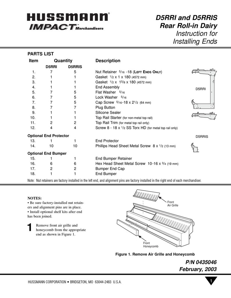
Hussmann IMPACT D5RRI Parts installation and removal guide


