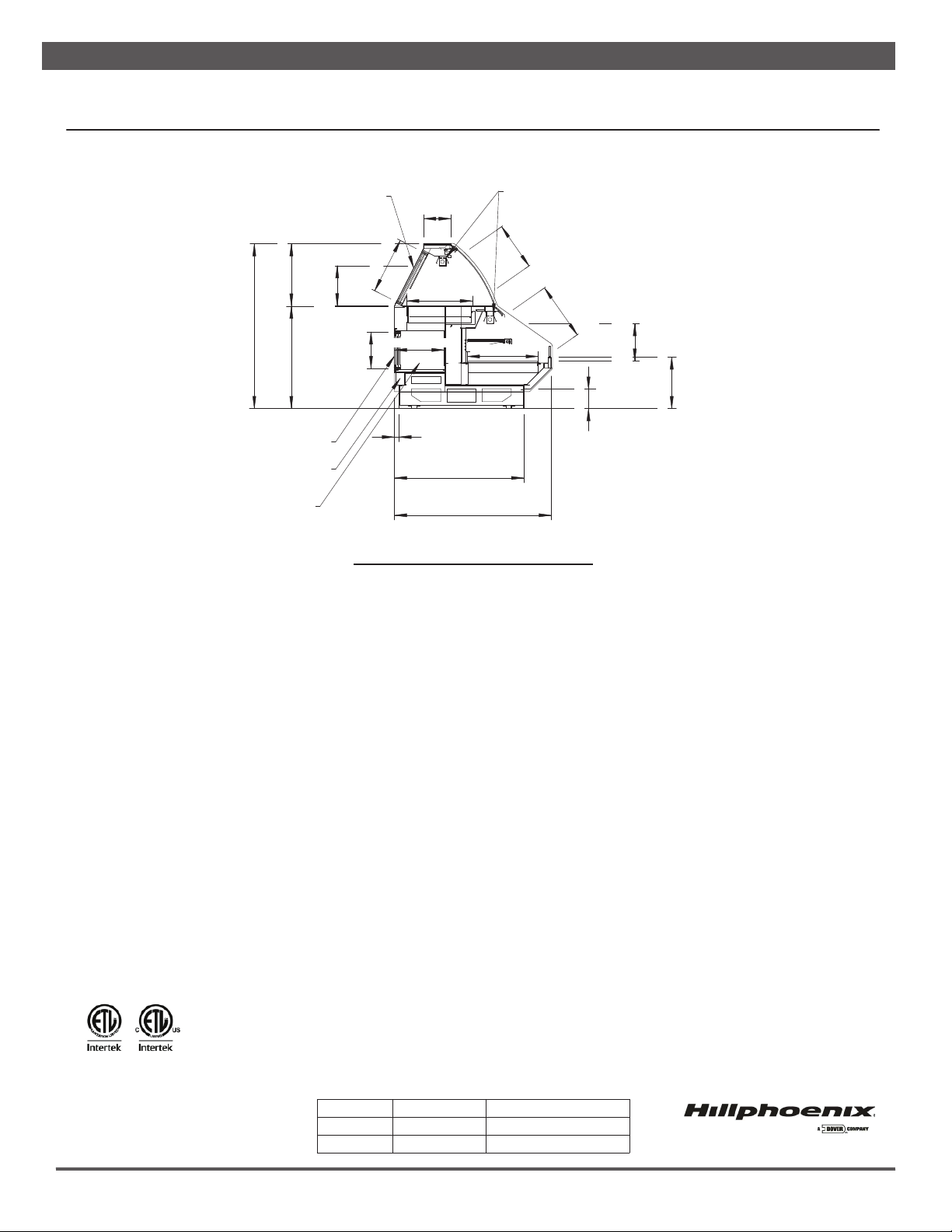
Hillphoenix DELI User manual

09/21
Technical Reference ...........................................2-6
General Information ............................................... 7
Installation ..........................................................8-9
Lighting, Heat & Power Supplies................... 10-11
Pre-Power Checklist ............................................12
Heat Controls & Settings .............................. 13-15
Case Cleaning ......................................................16
Touble Shooting Guide ........................................17
Parts Ordering ......................................................18
Appendices
Table of Contents
To ensure proper functionality and optimum performance, it is STRONGLY recommended that Hillphoenix specialty cases be installed/serviced by quali•ed tech-
nicians who have experience working with commercial refrigerated display merchandisers and storage cabinets. For a list of Hillphoenix-authorized installation/
service contractors, please visit our website at www.hillphoenix.com.
PTD-H-H/DELI
MULTI-DECK MERCHANDISER
I N S TA L L AT I O N & O P E R AT I O N S M A N U A L

ii

LIABILITY NOTICE
For Cases with Shelf Lighting Systems
Hillphoenix does NOT design any of its shelf lighting systems or any of its display cases with shelf lighting
systems for direct or indirect exposure to water or other liquids. The use of a misting system or water hose
on a display case with a shelf lighting system, resulting in the direct or indirect exposure of the lighting
system to water, can lead to a number of serious issues (including, without limitation, electrical failures,
•re, electric shock, and mold) in turn resulting in personal injury, death, sickness, and/or serious property
damage (including, without limitation, to the display itself, to the location where the display is situated
[e.g., store] and to any surrounding property). DO NOT use misting systems, water hoses or other devices
that spray liquids in Hillphoenix display cases with lighted shelves.
If a misting system or water hose is installed or used on a display case with a shelf lighting system, then
Hillphoenix shall not be subject to any obligations or liabilities (whether arising out of breach of contract,
warranty, tort [including negligence], strict liability or other theories of law) directly or indirectly resulting
from, arising out of or related to such installation or use, including, without limitation, any personal injury,
death or property damage resulting from an electrical failure, •re, electric shock, or mold.
P079211M, REVO
iii

Important
D A N G E R
▲
Indicates an immediate threat of death or seri-
ous injury if all instructions are not followed
carefully.
At Hillphoenix®, the safety of our customers and employees, as well as the ongo-
ing performance of our products, are top priorities. To that end, we include impor-
tant warning messages in all Hillphoenix installation and operations handbooks,
accompanied by an alert symbol paired with the word "DANGER", "WARNING", or
"CAUTION".
All warning messages will inform you of the potential hazard; how to reduce the
risk of case damage, personal injury or death; and what may happen if the in-
structions are not properly followed.
W A R N I N G
Indicates a potential threat of death or serious
injury if all instructions are not followed care-
fully.
▲
C A U T I O N
Indicates that failure to properly follow instruc-
tions may result in case damage.
▲
iv

Revision History
• new manual format_09/21
v

TECHNICAL REFERENCE
ENGINEERED FOR STORES WITH AMBIENT
CONDITIONS NOT TO EXCEED 75° AND 55%
RELATIVE HUMIDITY. DUE TO ENGINEERING
IMPROVEMENTS SPECIFICATIONS MAY CHANGE
WITHOUT NOTICE. ALL MEASUREMENTS ARE
TAKEN PER ASHRAE-72-2005 SPECIFICATIONS.
NUMBERS ARE BASED ON STANDARD CASE SIZES.
CONSULT ENGINEERING.
PTD-H-H
Self-Service Open Multi-Deck Merchandiser w/ Service Dome & DRS
4', 6', 8', 10' & 12' (Deli)
PTD-H-H
Rev. Date Rev. # Rev. Title
04-22-21 3 DATA UPDATE
03-11-21 2 LOGO UPDATE
SHIPPING WEIGHT
Case Weight
PTD-H-H ---
GENERAL NOTES:
• "---" Indicates that the feature is not an option on this case model and/or the data is not yet available at this time.
• (DRS) Dry Rear Storage
• Curved glass. (optional)
2

TECHNICAL REFERENCE
ENGINEERED FOR STORES WITH AMBIENT
CONDITIONS NOT TO EXCEED 75° AND 55%
RELATIVE HUMIDITY. DUE TO ENGINEERING
IMPROVEMENTS SPECIFICATIONS MAY CHANGE
WITHOUT NOTICE. ALL MEASUREMENTS ARE
TAKEN PER ASHRAE-72-2005 SPECIFICATIONS.
NUMBERS ARE BASED ON STANDARD CASE SIZES.
CONSULT ENGINEERING.
PTD-H-H
Self-Service Open Multi-Deck Merchandiser w/ Service Dome & DRS
4', 6', 8', 10' & 12' (Deli)
PTD-H-H
Rev. Date Rev. # Rev. Title
04-22-21 3 DATA UPDATE
03-11-21 2 LOGO UPDATE
NOTES:
• "---" Indicates that the feature is not an option on this case model and/or the data is not yet available at this time.
SERVICE DATA (DOME)
Case
Length
Top
Heaters
Bottom
Heaters Lights Shelves
Total Amps
(120/208-1-60)
Total Amps
(120/208-3-60)
Qnty
Watts
(Each) Qnty
Watts
(Each) Qnty
Watts
(Each) Qnty
Watts
(Each) L1 L2 L1 L2 L3
4' 3 400 3 400 2 40 --- --- 12.34 11.67 3.84 9.61 10.38
6' 4 400 4 400 3 40 --- --- 16.66 15.66 7.70 11.55 12.55
8' 6 400 5 400 6 40 --- --- 22.73 21.40 13.81 17.77 13.48
10' 7 400 6 400 5 40 --- --- 27.01 25.34 19.44 15.13 17.52
12' 8 400 7 400 6 40 --- --- 31.29 29.29 21.50 17.77 21.77
SELF-SERVICE (BASE)
Case
Length
Top
Heaters
Bottom
Heaters Lights Shelves
Total Amps
(120/208-1-60)
Total Amps
(120/208-3-60)
Qnty
Watts
(Each) Qnty
Watts
(Each) Qnty
Watts
(Each) Qnty
Watts
(Each) L1 L2 L1 L2 L3
4' 3 250 3 400 2 40 1 590 12.21 12.88 12.88 7.03 5.88
6' 4 250 4 400 3 40 2 426 16.61 17.61 13.16 9.40 8.60
8' 6 250 5 400 4 40 2 590 23.84 22.51 17.18 12.96 17.26
10' 7 250 6 400 5 40 2 720 26.87 28.54 17.18 21.37 17.40
12' 8 250 7 400 6 40 3 590 31.71 33.71 21.16 24.21 20.41
SERVICE/SELF-SERVICE
Case
Length
Total Amps
(120/208-1-60)
Total Amps
(120/208-3-60)
L1 L2 L1 L2 L3
4' 24.69 24.87 16.72 16.64 16.26
6' 31.48 31.48 20.86 20.95 21.15
8' 46.23 46.23 30.99 30.73 30.74
10' 54.02 54.02 36.62 36.50 34.92
12' 63.11 63.11 42.66 41.98 42.18
ELECTRICAL DATA
Case
Length
Fans
Per
Case
Control Fans
Dome Base
208 Volts 208 Volts
Amps Watts Amps Watts
4' 2 0.22 0.22 0.22 0.22
6' 3 0.22 0.22 0.22 0.22
8' 4 0.33 0.33 0.33 0.33
10' 4 0.44 0.44 0.44 0.44
12' 6 0.66 0.66 0.66 0.66
3

TECHNICAL REFERENCETECHNICAL REFERENCE
ENGINEERED FOR STORES WITH AMBIENT
CONDITIONS NOT TO EXCEED 75° AND 55%
RELATIVE HUMIDITY. DUE TO ENGINEERING
IMPROVEMENTS SPECIFICATIONS MAY CHANGE
WITHOUT NOTICE. ALL MEASUREMENTS ARE
TAKEN PER ASHRAE-72-2005 SPECIFICATIONS.
NUMBERS ARE BASED ON STANDARD CASE SIZES.
CONSULT ENGINEERING.
PTD-H-H
Self-Service Open Multi-Deck Merchandiser w/ Service Dome & DRS
4', 6', 8', 10' & 12' (Deli)
PTD-H-H
Rev. Date Rev. # Rev. Title
04-22-21 3 DATA UPDATE
03-11-21 2 LOGO UPDATE
LIGHTING DATA
Case
Length
Lights
Per
Row
Light
Length
Fluorescent Lighting
(Per Light Row)
Dome Base
Amps Watts Amps Watts
4' 1 3' --- --- 0.09 18.7
6' 2 2' --- --- 0.10 20.8
8' 2 3' --- --- 0.15 31.2
10' 2 4' --- --- 0.20 41.6
12' 3 3' --- --- 0.24 49.9
4

TECHNICAL REFERENCE
51" [129.5 cm]
6" [15.2 cm]
2 1/16" [5.2 cm]
145" [368.3 cm] 1" [2.5 cm]
42" [106.7 cm]
FRONT OF CASE
48 1/2" [123.2 cm] {4' case}
72 1/2" [184.2 cm] {6' case}
97" [246.4 cm] {8' case}
121" [307.3 cm] {10' case}
145 " [368.3 cm] {12' case}
POWER SUPPLY
TOEKICK
TOEKICK
8 15/16" [22.6 cm]
20 1/4" [51.5 cm]
33 5/16" [84.6 cm]
CASE HEIGHT
53 9/16" [136.1 cm]
21 3/8" [54.3 cm]
INTERIOR HEIGHT
13 1/16" [33.2 cm]
INTERIOR HEIGHT
12 3/16" [31.0 cm]
16 3/4" [42.5 cm]
6 5/16" [16.0 cm]
23 1/8" [58.7 cm]
1 1/2" [3.7 cm]
42" [106.7 cm]
51" [129.5 cm]
CERAMIC TOP HEAT
VISUALDISPLAY
191/2"[49.5cm]
VISUALDISPLAY
185/8"[47.3cm]
SLIDING
REAR LOAD DOORS
ELECTRICAL RACEWAY
12"
REAR SLIDING DOORS
(OPTIONAL)
LOWER REAR STORAGE
18 5/16"[46.6cm]
11 13/16" [30.0 cm]
FLAT GLASS
16 1/4" [41.1 cm]
ENGINEERED FOR STORES WITH AMBIENT
CONDITIONS NOT TO EXCEED 75° AND 55%
RELATIVE HUMIDITY. DUE TO ENGINEERING
IMPROVEMENTS SPECIFICATIONS MAY CHANGE
WITHOUT NOTICE. ALL MEASUREMENTS ARE
TAKEN PER ASHRAE-72-2005 SPECIFICATIONS.
NUMBERS ARE BASED ON STANDARD CASE SIZES.
CONSULT ENGINEERING.
PTD-H-H
Self-Service Open Multi-Deck Merchandiser w/ Service Dome & DRS
4', 6', 8', 10' & 12' (Deli)
PTD-H-H
Rev. Date Rev. # Rev. Title
04-22-21 3 DATA UPDATE
03-11-21 2 LOGO UPDATE
5

TECHNICAL REFERENCETECHNICAL REFERENCE
8 15/16" [22.6 cm]
20 1/4" [51.5 cm]
33 5/16" [84.6 cm]
CASE HEIGHT
53 9/16" [136.1 cm]
21 3/8" [54.3 cm]
16 3/4" [42.5 cm]
6 5/16" [16.0 cm]
1 1/2" [3.7 cm]
42" [106.7 cm]
51" [129.5 cm]
23 1/8" [58.7 cm]
12"
VISUALDISPLAY
159/16"[39.5cm]
VISUALDISPLAY
185/8"[47.3cm]
CERAMIC TOP HEAT
SLIDING
REAR LOAD DOORS
INTERIOR HEIGHT
12 3/16" [31.0 cm]
REAR SLIDING DOORS
(OPTIONAL)
ELECTRICAL RACEWAY
LOWER REAR STORAGE
INTERIOR HEIGHT
13 1/16" [33.2 cm]
11 13/16" [30.0 cm]
18 5/16"[46.6cm]
CURVED GLASS (OPTIONAL)
16 1/4" [41.1 cm]
ENGINEERED FOR STORES WITH AMBIENT
CONDITIONS NOT TO EXCEED 75° AND 55%
RELATIVE HUMIDITY. DUE TO ENGINEERING
IMPROVEMENTS SPECIFICATIONS MAY CHANGE
WITHOUT NOTICE. ALL MEASUREMENTS ARE
TAKEN PER ASHRAE-72-2005 SPECIFICATIONS.
NUMBERS ARE BASED ON STANDARD CASE SIZES.
CONSULT ENGINEERING.
PTD-H-H
Self-Service Open Multi-Deck Merchandiser w/ Service Dome & DRS
4', 6', 8', 10' & 12' (Deli)
PTD-H-H
Rev. Date Rev. # Rev. Title
04-22-21 3 DATA UPDATE
03-11-21 2 LOGO UPDATE
6

Thank you for choosing Hillphoenix for your food merchandising needs. This handbook contains important technical infor-
mation and will assist you with the installation and operation of your new Hillphoenix specialty cases. By closely following
the instructions, you can expect peak performance; attractive fit and finish; and long case life.
We are always interested in your suggestions for improvements (e.g. case design, technical documents, etc.). Please feel
free to contact our Marketing Services group at the number listed below. Thank you for choosing Hillphoenix, and we wish
you the very best in outstanding food merchandising.
CASE DESCRIPTION
This manual specifically covers the PTD-H-H deli application
self-service open multi-deck hot merchandiser with service
dome.
STORE CONDITIONS
Hillphoenix cases are designed to operate in an air-condi-
tioned store that maintains a 75°F (24°C) store temperature
and 55% (max) relative humidity (ASHRAE conditions). Case
operation will be adversely affected by exposure to excessively
high ambient temperatures and/or humidity.
SHIPPING CASES
Transportation companies assume all liability from the time a
shipment is received by them until the time it is delivered to
the consumer. Our liability ceases at the time of shipment.
RECEIVING CASES
Examine fixtures carefully and in the event of shipping dam-
age and/or shortages, please contact the Service Parts
Department at the number listed below.
CASE DAMAGE
Claims for obvious damage must be 1) noted on either the
freight bill or the express receipt and 2) signed by the carrier's
agent; otherwise, the carrier may refuse the claim. If damage
becomes apparent after the equipment is unpacked, retain all
packing materials and submit a written request to the carrier
for inspection within 14 days of receipt of the equipment.
Failure to follow this procedure will result in refusal by the
carrier to honor any claims with a consequent loss to the
consumer.
If a UPS shipment has been damaged, retain the damaged
material, the carton and notify us at once. We will file a claim.
LOST/MISSING ITEMS
Equipment has been carefully inspected to insure the highest
level of quality. Any claim for lost/missing items must be
made to Hillphoenix within 48 hours of receipt of the equip-
ment. When making a claim please use the number listed
below.
SERVICE PARTS & TECHNICAL SUPPORT
For service parts questions regarding our cases, please
contact our Service Parts Department at 1-844-HPX-PART
For technical questions regarding our cases, please contact
our Technical Support Department at 1-833-280-5714.
CONTACTING THE FACTORY
If you need to contact Hillphoenix regarding a specific fixture,
be certain that you have both the case model number and
serial number. (This information can be found on the data tag,
located at the top-left interior, rear exterior panel or interior
rear lower storage of the case. Location may vary based on
case design.)
Hillphoenix Specialty Products
703 Franklin Street, PO Box 478
Keosauqua, IA 52565
Website: www.hillphoenix.com
GENERAL INFORMATION
7

CASE INSTALLATION
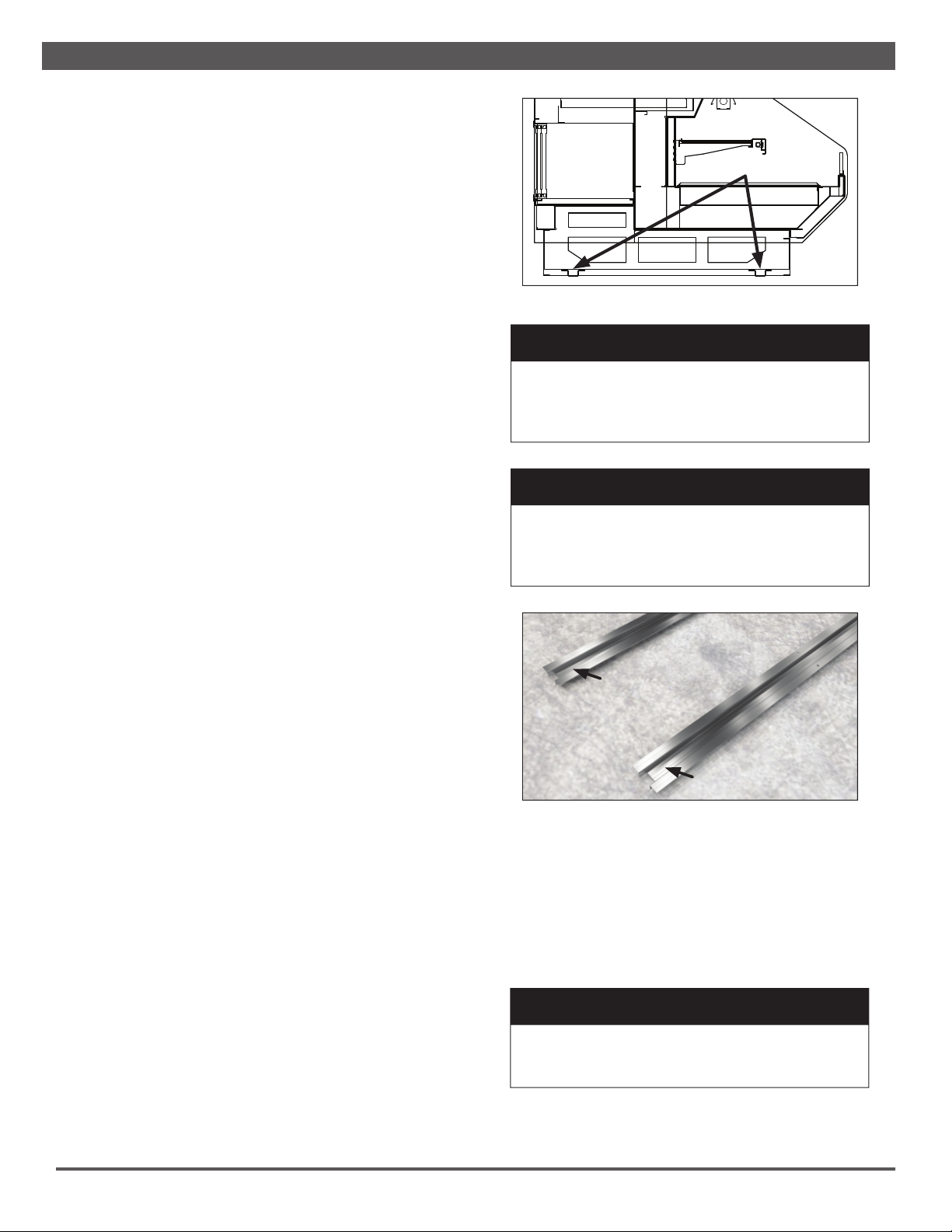
Fig. 1 Horizontal supports
SUPPORTS
FLOOR PREP
1. Ask the general contractor if your current copy of the build-
ing dimensions are the most recently issued. Also, ask for
the points of reference from which you should take dimen-
sions to locate the cases.
2. Using chalk lines or a laser transit, mark the floor where
the cases are to be located for the entire lineup. The lines
should coincide with the outside edges of the case feet.
3. Move case as close as possible to its permanent location.
Remove all crating and shipping braces above the ship-
ping pallet. Loosen the plastic dust cover from the pallet,
but leave cover over the case to protect it while removing
the case from the pallet.
4. Shipping braces with a sled runner construction can either
have metal brackets that can be removed with a screw
gun, or wood blocks that can be removed with a J-bar.
Note: Shipping braces are normally located at each
corner of the case. (Shipping braces used vary and are
based on case design for best transport.)
5. Carefully, if horizontal supports, lift case up and off the
pallet. Remove dust cover. Installation hardware ships in a
marked packet located inside the case.
6. Leveling is necessary to ensure proper operation. Locate
the highest point on the positioning lines as a reference
for determining the proper height of the shim-pack level-
ers. A laser transit is recommended for precision and
requires just one person. Level adjustable feet by twisting,
if applicable, or shim as necessary under horizontal sup-
ports as this will help ensure that the case is not settling
over time.
7. Locate horizontal support positions along the chalk line
(Fig. 1). Spot properly leveled shim packs at each support
location.
8. If necessary, drill a hole in each end of every horizontal
support (Fig. 2) and fasten to the floor with concrete
anchors. Note: The holes do not need to be in the exact
locations specified here. Be sure that the anchors are
close to the end of the horizontal supports and at each
corner of the case.
LOCATION
This hot display case has been designed for displaying and
storing perishable food product. It is engineered for air-con-
ditioned stores with a maximum ambient of 75°F and 55%
relative humidity.
When selecting the location for placement of this case, avoid
the following conditions:
Excessive Air Movement
1. Doors
2. Air-conditioned vents
3. Other air sources C A U T I O N
Locate the horizontal supports under unit before
removing from pallet. Failure to do so will dam-
age the finished metal if correct lift points are
not identified prior to removal.
▲
2. Once the case is properly placed on the shim packs, check
the horizontal level of the case by placing a bubble level
on the front sill. Add/remove shim packs as needed.
LINE-UP & INSTALLATION
Single Case
1. Move the case into position. Using a “J” bar, raise the end
of the case (under cross support), and lower the horizontal
support on to the shim packs. Repeat on the other end of
the case.
C A U T I O N
These cases are not designed for excessive
external weight. Do not walk on top or inside
of cases. Doing so may result in case damage
and/or personal injury.
▲
W A R N I N G
Be certain that your hands and feet are out of
the way before lowering the case. Failure to do
so may result in serious injury.
▲
Fig. 2 Seismic anchoring locations
8

CASE INSTALLATION
Fig. 3 Bolt locations
Multi-Case
1. Remove any shelves (discard the shelf clips) and/or loose
items from the cases that may interfere with case joining.
Keep all loose items as they will be used later in the instal-
lation process.
2. Follow the single-case installation instructions for the •rst
case,excluding #6, then position the next case in the line-
up approximately 3’ away.
3. Move the second case to a position that is approximately
6" from the •rst case, then position case on the shim
packs.
4. Push the cases tightly together, then lightly bolt them
together through the holes provided (Fig. 3). Tighten all the
joining bolts until all margins are equal. Be careful not to
over tighten.
C A U T I O N
Installation of 3rd-party materials may result in
diminished case performance.
▲
ELECTRICAL
Electrical hookups are made through the electrical raceway
that can be accessed by removing the rear raceway panel.
For case-to-case wiring, run conduit between the power supply
boxes or run wiring through the raceway. When connecting to
the power supply on the case, •eld wiring should exit box from
the side furthest away from case wiring to allow more room in-
side for wiring connections. Always check the data tag located
on left end exterior panel or top interior of the case. The case
must be grounded. For more detailed electrical wiring informa-
tion (see Appendix A1).
C A U T I O N
Be certain that all electrical connections are
compliant with local codes.
▲
5. Repeat steps 3 and 4 of this sequence for all remaining
cases. Be certain to properly level all cases.
6. Properly align the front panels as needed, then install, if
3. Install the bumper, if applicable, into pre-attached bumper
track and snap into place.
4. After suf•cient time has passed to allow for bumper
shrinkage, cut away the excess bumper for •nal •t and •n-
ish. Be certain to use an appropriate cutting tool (tubing-
or PVC-cutter) to ensure a smooth cut.
5. Install case shelves and reconnect lights with the white
power cord(s) and the heat with the black power cord(s).
Color matching white/black receptacles can be found at
opposite ends of the inside back of the case. Be aware
that differing shelf con•gurations will affect energy con-
sumption and case performance. Be sure that the T-8
light caps and holders are still positively engaged. Dur-
ing shipping it is possible for these to loosen.
6. Install toekick back onto the base of case.
applicable, front panel trim (supplied).
7. Install the bumper into pre-attached bumper track and
snap into place.
8. After suf•cient time has passed to allow for bumper
shrinkage, cut away the excess bumper for •nal •t and •n-
ish. Be certain to use an appropriate cutting tool (tubing-
or PVC-cutter) to ensure a smooth cut.
9. Install case shelves and reconnect lights. Be aware that
differing shelf con•gurations will affect energy consump-
tion and case performance. Be sure that the T-8 light
caps and holders are still positively engaged. During
shipping it is possible for these to loosen.
10. Install toekick back onto the base of case.
C A U T I O N
Be sure that the T-8 light caps and holders are
still positively engaged. During shipping it is pos-
sible for these to loosen. Prior to install check all
T-8 light connection points prior to installation
and supplying power.
▲
9

GENERAL LIGHTING INFORMATION
Hillphoenix hot cases are equipped with T-8 lights and feature
specially designed light reflectors in the cornice to improve the
illumination of products. The T-8 electronic ballasts operate
both the cornice and shelf lights, and are located above the
cornice reflectors.
The lighting system has an ON/OFF switch located in the race-
way, power box or at the inside back of the case. Once a case
has been properly positioned in the store and an electrician
has connected the lighting circuit, the lights may be turned on
to verify that they are connected and functioning properly.
To ensure peak performance, it is advisable to run the lighting
systems only when the store climate control is on and the case
heat is started. Note: It is highly recommended that the ambi-
ent store temperature not exceed 80°F
D A N G E R
▲
SHOCK HAZARD
Always disconnect power to case when cleaning,
servicing or con!guring components of the light-
ing system. Failure to do so may result in serious
injury or death.
Fig. 4 T-8 light power cord (WHITE)
W A R N I N G
▲
Using improper DC power supplies may damage
the luminaires, resulting in sub-standard opera-
tion and increased chances of safety issues/
injury.
Fig. 5 T-8 cap and lamp holder
LAMP HOLDER
CAP
SHELF LUMINAIRES
1. Unplug the white T-8 lamp power cords located at the
inside-back of the case below the lamp being replaced
(Fig. 4).
Fig. 6 Positive engagement
HEATED SHELVES
Unlike the shelf luminaries that are designated with a white re-
ceptacle and cord; the heat receptable and cord designation is
black (Fig. 7). The two, light and heat cords, are located at op-
2. Carefully seperate the cap from the lamp holder on both
ends of the T-8 lamp (Fig. 5). Simultaneously pull down at
both ends of the old T-8 lamp to remove.
3. Push and snap the new T-8 lamp into place on the lamp
holder. When the T-8 is properly seated, the lamp button
- which secures the T-8 to the lamp holder - will be clearly
visible through the lamp button hole. The cap should be
pushed all the way down (Fig. 6) for positive engagement
indicator. Be sure that the T-8 light caps and holders are
still positively engaged. During shipping it is possible
for these to loosen.
C A U T I O N
Be sure that the T-8 light caps and holders are
still positively engaged. During shipping it is pos-
sible for these to loosen. Prior to install check all
T-8 light connection points prior to installation
and supplying power.
▲
TECHNICAL REFERENCELIGHTING, HEAT & POWER SUPPLIES
10

SHELF LUMINAIRES
Removing shelf luminaires:
1. Unplug the luminaire.
2. Pinching the latching clips inward at the ends of the lumi-
naire, rotate luminaire up at each end until hooks are free,
then remove.
Re-installing shelf luminaires:
1. Place hook into shelf roll form at shelf front and rotate
rear of luminaire toward the shelf.
2. Depress the rear clip so that luminaire can !nish rotation
and until clip engages the shelf bracket.
NON-SHELF LUMINAIRES
Removing non-shelf luminaires:
1. Simultaniously squeeze the plastic clips at each end.
2. When the hooks are disengaged, pull the luminaire free.
Re-installing non-shelf luminaires:
1. Align the 4-pole jack with the 4-pole connector on the clip-
in luminaire.
2. Push into place - side clips will engage on the sheet metal
of the case.
3. Fasten anti-tamper bracket into sheet metal of case with
#8 screw at end opposite of the 4-pole in-line connector.
D A N G E R
▲
SHOCK HAZARD
Always disconnect power to case when cleaning,
servicing or con!guring components of the light-
ing system. Failure to do so may result in serious
injury or death.
Fig. 9 Clear view of the ballasts
BALLAST
Fig. 7 Heat power cord (BLACK)
BALLAST/POWER SUPPLY ACCESS
To gain access to the ballasts or power supplies remove the
panel located above the rear toe kick (Fig. 9)
W A R N I N G
INCANDESCENT BULBS
When replacing an overhead incandescent bulb
(Fig. 8) be sure to use only a shatterproof or
plastic bulb as a replacement. Use of any other
bulb, especially one made of glass, may lead to
death or serious injury if broken inside of the
case and/or near food product.
▲
Fig. 8 Incandescent bulb
posite ends of the same shelf and the color designated white/
black receptacles to match at their corresponding end of the
inside back of the case.
In order to supply heat to the shelves this black heat cord must
be plugged in to it's designated receptacle during use at all
times.
LIGHTING, HEAT & POWER SUPPLIES
11

Have you thoroughly examined the case for shipping damage? (see pg. 7)
Have you checked the horizontal level of the case?
(see pg. 8)
Have you applied the sealant to the end breakers of adjoining cases?
(see pg. 9)
Have you sealed the case-to-case joints by applying caulk and acrylic tape to
the end frame seam? (see pg. 9)
Have you installed the toekick? (see pg. 9)
Have you checked that all T-8 light caps and holders are positively engaged?
(see pg. 10)
After powering-up the case, be certain that all of the steps listed below have
been completed to ensure proper case functionality, safety and compliance with
warranty terms.
1. Check all lights and heating elements to ensure they are all functioning
properly.
2. Check case temperature and adjust controller as needed.
Before powering-up the case, be certain that all of the steps listed below have
been completed to ensure proper case functionality, safety and compliance with
warranty terms.
TECHNICAL REFERENCEPRE-POWER CHECKLIST
12

HEAT CONTROLS
Hillphoenix case hot wells are equipped with digital controls
(Fig. 10). To adjust press the appropriate arrow •rmly. There is
one control per well for individual functions.
The controls are normally grouped in clusters. Each case will
have Control #1 and one or more Control #2.
PREHEATING
Turn on power switch and set controls to level 9 for preheat-
ing. Place empty pans or tiles in all wells. Let unit operate with
empty pans or tiles for 60 minutes before loading with product.
Adjust controls to desired levels before loading case with prod-
uct. Putting hot food in a case this has not reached full tempera-
ture will cause product temperature to drop quickly. All product
must be preheated to 175oF. It is essential that product be fully
cooked and heated prior to stocking the case. Check product
temperature of larger pieces when cooking different size items.
It takes longer for larger pieces to reach desired temperature.
AB C
D
E
F
A Heat Active - The heating element turns ON and OFF, once every second. The heat active dot
blinks ON/OFF each time the element is switched ON/OFF. If the dot is not blinking check to
ensure that the heating element is running properly.
B Lights - The top light is for illumination only. It is not for control of the upper heat.
C Case Power - Turn power ON/OFF at the switch. Press buttons firmly to ensure proper ON/OFF.
D Main Power - When controls are OFF the main power light should remain lit.
E Heating Levels - Adjust levels UP or DOWN.
F Heating Levels (Range) 0 = OFF
1 = Lowest
9 = Highest
Control #1
This is the largest control. Once settings are determined, use
this control to turn power ON and OFF for the case. Reset when
ambient conditions change or product changes.
Fig. 10 Digital heat controls
HEAT CONTROLS & SETTINGS
13

W A R N I N G
Always keep product within the designated
heated areas. Failure to do so may result in
case malfunction and product losing proper
temperature, resulting in sub-standard opera-
tion and increased chances of food contamina-
tion.
▲
W A R N I N G
All product must be fully cooked prior to being
stocked in the case. Failure to do so may result
in serious illness or death.
▲
PRODUCT DISPLAY & SETTINGS
This merchandiser is designed to operate without water in the
well. Adding water will cause the case to expend many BTU's
in order to heat the water and not the product. This may cause
condensation to collect on the font glass (if applicable) of ser-
vice cases.
For best results product should be arranged by product type
with groupings of like product together.
Load Limits
1. Product must be 6" below the top heater in self-service
cases and contained in the tile or well area.
2. The well must be completely covered with tiles or pans
whether !lled with product or empty.
Control #2
At least one and possibly several of these controls will be on
each case depending on the number of wells. There will always
be one control per well.
Control #3
This control is only present in a combination service/self-ser-
vice case for the overhead heat.
Functions: Well Control
Range: (0-9)
0 = OFF
1 = Lowest Setting
9 = Highest Setting
Functions: Overhead Heat Control
Range: (0-9)
0 = OFF
1 = Lowest Setting
9 = Highest Setting
Common Settings
Product that is immersed in liquid is easier to keep hot. Prod-
ucts like fried foods are the hardest to maintain temperature.
Functions: Case Power ON/OFF
Lights ON/OFF
Top Fan ON/OFF
Overhead Heat
Range: (0-9)
0 = OFF
1 = Lowest Setting
9 = Highest Setting
TECHNICAL REFERENCEHEAT CONTROLS & SETTINGS
14

To adjust temperatures, change the heat setting one number at
a time by holding the UP or DOWN button 2-3 seconds to ensure
change made. Allow 1-2 hours for the case temperature to even
out before continuing. The settings will need to be adjusted to
your specific product and store conditions. Use these settings
as a starting point.
Once the correct setting is found, the controls may be left at
that setting, and turned ON and OFF using the power switch on
the main control. The case must be turned on 1 hour before
placing the product. Be sure that all wells are covered with pans
or tiles all times whether filled with product or empty.
Recommended: 5-6 = Overhead Controls
5-6 = Fried Foods
2-5 = Immersed Foods
CASE AIR TEMPERATURE
The case air temperature may not be as high as the desired
product temperature. This case is designed to produce long
wave radiant heat. This type of heat penetrates the food and
keeps it warm from the inside out. Therefore, the air tempera-
ture may not be the same as the product temperature. Measure
product interior temperature to determine the correct settings,
not the air temperature for the best results.
UNIT SHUTDOWN
Turn case power to OFF on Control #1. It is not necessary to
adjust well or overhead heat controls. Remove product, turn off
case lights and allow the case to cool completely before clean-
ing.
HEAT CONTROLS & SETTINGS
15

Fig. 11 Rear load door removal
Rear Load Doors
1. Remove the rear sliding doors on the back of the case
and clean. To remove: push up and pull out (Fig. 11).
Note: The same applies for optional rear lower storage
doors (RRS/DRS).
2. Use a spray bottle !lled with an approved mild detergent
and warm water.
3. Use a clean, disposable cloth (approved item) to thorough-
ly clean all areas of the case.
4. Wipe down doors with a clean, disposable cloth (approved
item).
5. Place the cleaned doors on a clean sanitized surface until
they are dry.
CASE CLEANING
A periodic cleaning schedule should be established to maintain
proper sanitation, insure maximum operating efficiency, and
avoid the corrosive action of food fluids on metal parts that are
left on for long periods of time. We recommend that all heat-
ed surfaces be kept clear of excess food daily and a complete
cleaning take place once a week. Further suggestions for case
cleaning include the following:
• To avoid shock hazard, be sure all electrical power is turned
off before cleaning. In some installations, more than one
disconnect switch may have to be turned off to completely
de-energize the case.
• Allow cases to be turned off long enough to cool before
starting the cleaning process.
• Clean from top to bottom when cleaning the display case to
avoid cross contamination.
• If any potentially harmful cleaners are used, be certain
to provide a temporary separator (e.g., cardboard, plastic
wrap, etc.) between those cases that are being cleaned
and those that may still contain product.
• Avoid spraying any cleaning liquids directly on the electrical
connections, steam cleaning or using excessive amounts
of water.
• If the case is equipped with doors be sure to leave them
open until the case is completely dry.
• Remove toekick and clean underneath the case with a
broom and a long-handled mop. Use warm water and a dis-
infecting cleaning solution when cleaning underneath the
cases.
D A N G E R
▲
SHOCK HAZARD
Always disconnect power to case when servicing
or cleaning. Failure to do so may result in serious
injury or death.
W A R N I N G
Always let the case cool before cleaning. Failure
to do so may result in sub-standard operation
and increased chances of safety issues/injury.
▲
TECHNICAL REFERENCECASE CLEANING
16
This manual suits for next models
1
Table of contents
Other Hillphoenix Merchandiser manuals