Hillphoenix 3NDML-NRG User manual
P089172B
V1.01
09/13
MULTI-DECK MERCHANDISER
INSTALLATION & OPERATIONS MANUAL
To ensure proper functionality and optimum performance, it is STRONGLY recommended that Hillphoenix display cases be installed/serviced
by qualied technicians who have experience working with commercial refrigerated display merchandisers and storage cabinets. For a list of
Hillphoenix-authorized installation/service contractors, please visit our Web site at www.hillphoenix.com.
3NDML-NRG
General Information ....................................... 2
Case Installation .......................................... 3-4
Case Connections .......................................... 5
Pre-Power Checklist ....................................... 6
Lighting and Power Supplies ......................... 7
Airow, Defrost & Temperature Control ....... 8
Fans & Case Maintenance .............................. 9
Appendix ....................................................... 10
Table of Contents
COMPONENT
C
L
A
S
S
I
F
I
E
D
EPH
COMPONENT

Copyright © 2013 by Hillphoenix
All rights reserved. No part of this document may reproduced or transmitted in any form or by any means - i.e., electronic
or mechanical, including photocopying, recording or any other information storage and retrieval system - without express
written permission from Hillphoenix.
VERSION 1 (07/13)
• New manual format
V1.01 (07/13)
• Updated Electrical Data (Appendix A)
REVISION HISTORY
ii

IMPORTANT NOTICES
LIABILITY NOTICE
For Cases with Shelf Lighting Systems
Hillphoenix does NOT design any of its shelf lighting sys-
tems or any of its display cases with shelf lighting systems
for direct or indirect exposure to water or other liquids. The
use of a misting system or water hose on a display case
with a shelf lighting system, resulting in the direct or indirect
exposure of the lighting system to water, can lead to a num-
ber of serious issues (including, without limitation, electri-
cal failures, re, electric shock, and mold) in turn resulting
in personal injury, death, sickness, and/or serious property
damage (including, without limitation, to the display itself,
to the location where the display is situated [e.g., store] and
to any surrounding property).
DO NOT use misting systems, water hoses or other devic-
es that spray liquids in Hillphoenix display cases with light-
ed shelves. If a misting system or water hose is installed
or used on a display case with a shelf lighting system, then
Hillphoenix shall not be subject to any obligations or liabili-
ties (whether arising out of breach of contract, warranty,
tort [including negligence], strict liability or other theories
of law) directly or indirectly resulting from, arising out of or
related to such installation or use, including, without limita-
tion, any personal injury, death or property damage result-
ing from an electrical failure, re, electric shock, or mold.
P079211M, REVO
DANGER!
Indicates an immediate threat of serious
injury or death if all instructions are not fol-
lowed carefully.
CAUTION!
Indicates the potential threat of injury if all
instructions are not followed carefully.
ATTENTION!
Indicates an important point of information
that is key to ensuring proper case func-
tionality.
SERVICE NOTICE
To ensure proper functionality and optimum performance,
it is strongly recommended that Hillphoenix display cases
be installed/serviced by qualied technicians who have ex-
perience working with commercial refrigerated display mer-
chandisers and storage cabinets. For a list of Hillphoenix-
authorized installation/service contractors, please visit our
Web site at www.hillphoenix.com.
PRECAUTIONARY NOTICES
At Hillphoenix®, the safety of our customers and employ-
ees, as well as the ongoing performance of our products,
are top priorities. To that end, we call out important mes-
sages in all Hillphoenix installation and operations hand-
books with an accompanying alert symbol. All of these
notices are meant to provide information about potential
dangers to personal health and safety—as well as risks of
case damage—if the instructions are not carefully followed.
R-744 (CO2) NOTICE
For Systems Utilizing R-744 (CO2) Refrigerant
For refrigeration units that utilize R-744 (CO2), pressure
relief and pressure-regulating relief valves may need to be
installed based on the system capacity. The valves need
to be located such that no stop valve is positioned between
the relief valves and the parts or section of the system be-
ing protected.
When de-energizing refrigeration units containing R-744
(CO2), venting of the R-744 (CO2) refrigerant may occur
through the pressure regulating relief valves. These valves
are located on the refrigeration system and not on the case
model. If venting does occur, the valve must not be de-
feated, capped, or altered by any means.
GLYCOL NOTICE
For Systems Utilizing Glycol Refrigerant
Use of glycol as a secondary refrigerant must be carried
out in accordance with the procedures set forth in the Sec-
ond Nature Medium Temperature Secondary Refrigeration
Installation Manual, which is available for download at the
Hillphoenix website here: http://goo.gl/JIWd77
Additionally, Hillphoenix uses and recommends Dow gly-
col-based coolants, which contain specially formulated in-
dustrial inhibitors that help to prevent corrosion in display
cases. Over time, the effectiveness of these inhibitors de-
teriorates, increasing the chance for corrosion. We rec-
ommend testing of glycol solutions annually through the
Dow lab. The service is free for systems containing over
250 gallons of glycol coolants, while the cost is approxi-
mately $100 for smaller systems. For more information,
see Dow’s DOWFROST and DOWFROST HD Guide here:
http://goo.gl/v6i1iQ
CAUTION!
Under no circumstance should any com-
ponent be replaced or added without
consulting Hillphoenix Field Service En-
gineering. Utilizing improper components
may result in serious injury to persons or
damage to the refrigeration system.
iii

GENERAL INFORMATION
Thank you for choosing Hillphoenix for your food merchandising needs. This handbook contains important technical infor-
mation and will assist you with the installation and operation of your new Hillphoenix display cases. By closely following
the instructions, you can expect peak performance; attractive fit and finish; and long case life.
We are always interested in your suggestions for improvements (e.g. case design, technical documents, etc.). Please feel
free to contact our Marketing Services group at the toll-free number listed below. Thank you for choosing Hillphoenix, and
we wish you the very best in outstanding food merchandising.
CASE DESCRIPTION
This manual covers the 3NDML-NRG multi-deck merchan-
diser. For electrical data and case dimensions, see
Appendix A.
STORE CONDITIONS
Hillphoenix cases are designed to operate in an air-condi-
tioned store that maintains a 75°F (24°C) store tempera-
ture and 55% (max) relative humidity (CRMA conditions).
Case operation will be adversely affected by exposure to
excessively high ambient temperatures and/or humidity.
REFRIGERATION SYSTEM OPERATION
Air-cooled condensing units require adequate ventilation
for efficient performance. Machine-room temperatures
must be maintained at a minimum of 65°F in winter and a
maximum of 95°F in summer. Minimum condensing tem-
peratures should be no less than 70°F.
RECEIVING CASES
Examine fixtures carefully and in the event of shipping
damage and/or shortages, please contact the Service
Parts Department at 1-800-283-1109.
CASE DAMAGE
Claims for obvious damage must be 1) noted on either the
freight bill or the express receipt and 2) signed by the car-
rier's agent; otherwise, the carrier may refuse the claim. If
damage becomes apparent after the equipment is
unpacked, retain all packing materials and submit a written
request to the carrier for inspection within 14 days of
receipt of the equipment.
LOST/MISSING ITEMS
Equipment has been carefully inspected to insure the high-
est level of quality. Any claim for lost/missing items must
be made to Hillphoenix within 48 hours of receipt of the
equipment.
SERVICE & TECHNICAL SUPPORT
For service or technical questions regarding display cases,
please contact our Case Division Customer Service
Department at the toll-free number listed below. For ques-
tions regarding our refrigeration systems or electrical distri-
bution centers, please contact our Systems Division
Customer Service Department at 1-770-388-0706.
PARTS ORDERING
If you need to contact Hillphoenix regarding specific fix-
tures/parts, call 1-800-283-1109 and ask for a Service
Parts Representative. Provide the following information
about the part you are ordering:
• Model number and serial number* of the case for which
the part is intended.
• Length of the part (if applicable).
• Color of part (if painted) or color of polymer part.
• Whether part is for left- or right-hand application.
• Quantity
*Serial plate is located inside the case on the top-left side.
If the parts are to be returned for credit, ask the Parts
Department to furnish you with a Return Material
Authorization Number.
Hillphoenix
1925 Ruffin Mill Rd.
Colonial Heights, VA 23834
Mon.-Fri. (8 a.m to 5 p.m EST)
Tel: 1-800-283-1109
Fax: 804-526-7450
Web site: www.hillphoenix.com
2

FLOOR PREP
1. Ask the general contractor if your current copy of the
building dimensions are the most recently issued.
Also, ask for the points of reference from which you
should take dimensions to locate the cases.
2. Using chalk lines or a laser transit, mark the oor
where the cases are to be located for the entire lineup.
The lines should coincide with the outside edges of the
case feet.
3. Leveling is necessary to ensure proper case alignment
and to avoid potential case damage. Locate the high-
est point on the positioning lines as a reference for
determining the proper height of the shim-pack level-
ers. A laser transit is recommended for precision and
requires just one person.
4. Locate basehorse positions along the chalk line. Spot
properly leveled shim packs at each basehorse loca-
tion.
LINE-UP & INSTALLATION
Single Case
1. Roll the case into position, leaving a minimum of 2"
between the back of the case and the wall. Using a
“J” bar, raise the end of the case (under cross sup-
port), remove the caster assembly (Fig. 1), and lower
the basehorse on to the shim packs. Repeat on the
other end of the case.
2. Once the basehorse is properly placed on the shim
packs, check the vertical plumb of the case by plac-
ing a bubble level on the rear wall. Add/remove shim
packs as needed. For the horizontal level, repeat this
process after placing the bubble level on the front sill.
Multi-Case
1. Remove the shelves (discard the shelf clips) and any
loose items from the cases that may interfere with case
joining (e.g. shipping braces, mirror assemblies, etc).
Keep all loose items as they will be used later in
the installation process.
2. Remove the return air grill at the case joint. The grill
lifts out without fasteners and may be easily removed
to gain clear access to the case-to-case joining bolts.
3. Follow the single-case installation instructions for the
rst case, then position the next case in the line-up ap-
proximately 3’ away. Remove the casters on the end
that is closest to the rst case.
4. Apply the foam tape gasket (supplied) and a bead of
butyl or silicone sealant to the end of the rst case (Fig.
2). From the opposite end, push the second case to
a position that is approximately 6" from the rst case,
then remove the remaining casters and position case
on the shim packs.
= bolt holes
X = foam tape gasket
O = butyl or silicone sealant
NOTE: It is recommended that cases
be bolted together in the numbered
order indicated in the diagram.
X
X
X
X
X
X
XXXXXXXXXXXXXXXXXXXXXXXXXXXXXXXXXXXXXXXXXXXXXXXXX
X
XXXXXX
XXX
XXXXXX
XX
X
X
X
XXX
XXXX
XX
X
X
X
XX
XX
XXXXXX
X
XX
X
XX
XX
XXXXXXXXXXXXXXX
X
XXXXXXXX
X
XXX
X
XX
XX
X
X
XX
X
XXX
X
XXXXXXXXX
X
XXXX
XXX
X
X
X
X
XXXX
X
X
XX
X
XXX
X
XXX
XX
XXXXXXXXXXXXXX
X
XXXX
XX
XX
X
XXXXXXXX
X
X
X
XXX
X
XXX
XX
XXX
XXXXXXXXXXXX
OOOOOOOOOOOOOOOOOOOOOOOOOOOOOOOOOOOO
OOOOOOOOOOOOOOOOOOOOOOOOOOOOOOOOOOOOOOOOOOOOOOOOOOOOOOOOOOOOOOOOOOOOOOOOOOOOOOOOOOOOOOOOOOOO
O
O
OOOOOOOOOOOOOOOOOOOOOOOOOOOOOOOOOOOOOOO
O
OOOOOO
O
OOOOOOOOOOOOOOOOOOOOOOOOOOOOOOOOOOOO
OOO
O
O
O
O
O
O
O
O
O
O
O
O
O
O
O
O
O
O
O
O
O
O
1
3 5
4
Fig. 2 Bolt holes, foam tape gasket and sealant
2
CASE INSTALLATION
CAUTION!
Be certain that your hands and feet are
out of the way before lowering the case
after the removal of the casters. Failure
to do so may result in serious injury.
Fig. 1 Removing the casters is an easy process. Simply flatten and
remove the cotter pins that are holding the casters in place. Then
lift the case with a “J” bar and slide the caster assemblies out. The
dismantled casters can now be discarded.
COTTER
PIN
CASTER
3

TRIM OUT
1. Seal the case-to-case joints with caulk (supplied), then
apply acrylic tape (supplied) over the pipe-chase seam
(Fig. 3). The tape acts as a watershed preventing wa-
ter from settling in the case joint.
5. Loosen the cornice joint at case end (cornice screws
are located on top of the case). Be certain that cornice
joints and pins are properly aligned. Cases are now
ready to be joined.
6. Push the cases tightly together, then lightly bolt them
together through the holes that are provided (Fig. 2).
Tighten all the joining bolts until all margins are equal.
Be careful not to over tighten.
7. Repeat steps 2-6 of this sequence for all remaining
cases. Be certain to properly level all cases.
8. If seismic brackets are included, see Appendix D for
detailed installation instructions.
CASE INSTALLATION
2. Re-install shelves. Be aware that differing shelf con-
gurations will affect energy consumption and case
performance.
3. Tighten all cornice joints as needed (Fig. 4). Working
outward from the center of the line-up, loosen the fas-
teners on the top and slide the cornices in one direction
so that each joint aligns tightly together. Tighten the
fasteners on top and apply an external joint band on
the extreme ends of the lineup if a gap exists.
4. Properly align the front panels as needed, then install
the front panel trim (supplied).
5. Attach the one-piece kick plate to the factory installed
kickplate retainers with the screws provided.
Fig. 3 Sealing the pipe chase
ACRYLIC
TAPE
PIPE
CHASE
ATTENTION!
Installation of 3rd-party materials may
result in diminished case performance.
Fig. 4 Cornice joints
CORNICE
ALIGNMENT
PIN
CORNICE
JOINT
4
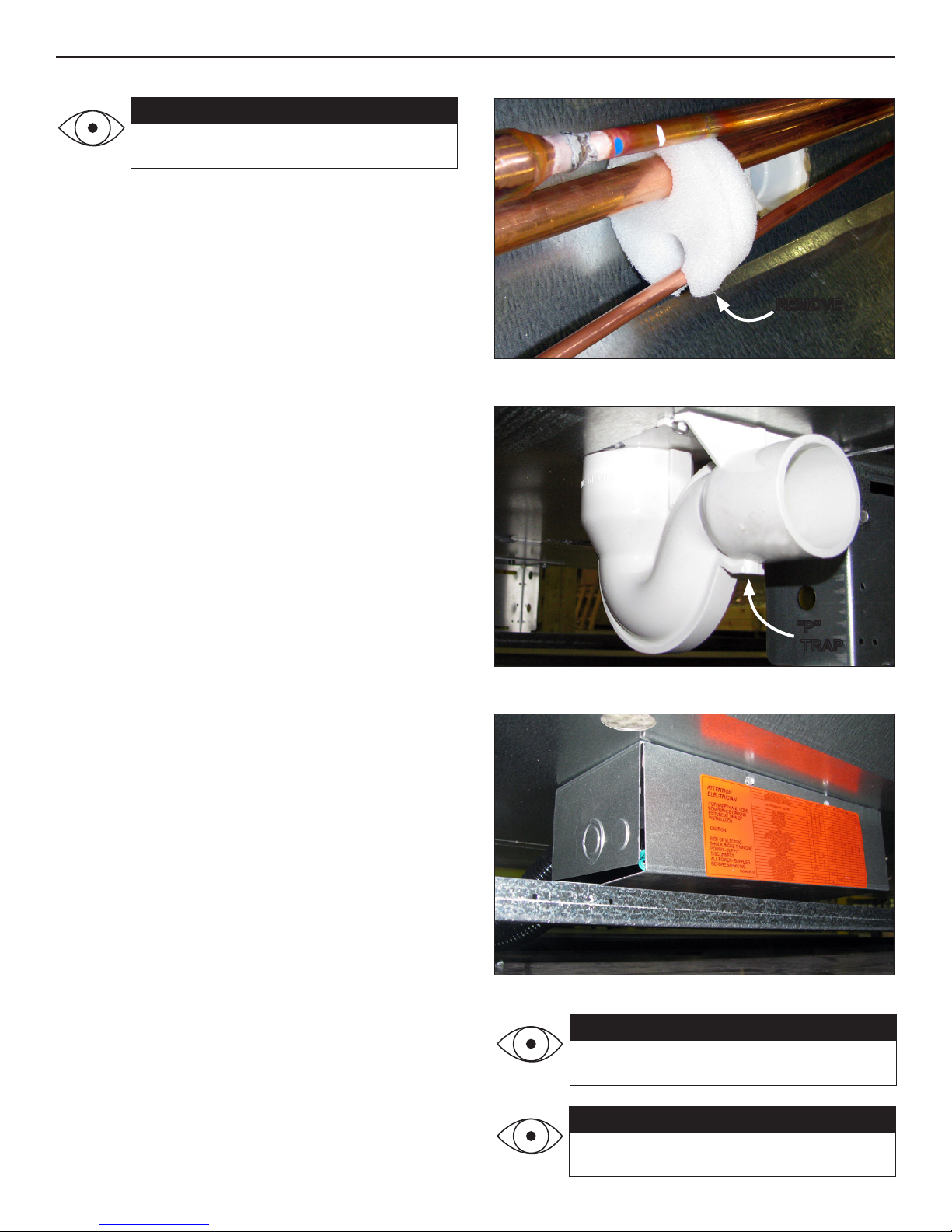
Fig. 5 Remove the shipping blocks
REMOVE
REFRIGERATION
Refrigeration piping connections for the 3NDML-NRG case
are made at the front-right area of the case, fully visible in
front of the fan plenum.
If hot gas defrost is utilized, suction lines to each case in
the circuit should be of equal distance from the main suc-
tion line. The expansion valve and other controls - located
on the left-hand side of the case - are accessible by lifting
the two left-hand deck pans (lifting the fan plenum is not
required).
Before operating the case, be certain to remove the ship-
ping blocks (Fig. 5) that protect the refrigeration lines dur-
ing shipping. If it becomes necessary to penetrate the case
tank in any area, be certain to seal any open gaps after-
wards with canned-foam sealant and white RTV.
CASE CONNECTIONS
ATTENTION!
If brazing is necessary, place wet rags
around the area to avoid tank damage.
ATTENTION!
Be certain that all piping and electrical
connections comply with local codes.
Fig. 7 Junction box beneath case
PLUMBING
The drain outlet is specially molded out of PVC material
and is located in the front-center of the case for convenient
access. The “P” trap, furnished with the case, is construct-
ed of schedule 40 PVC pipe (Fig. 6). Care should be given
to ensure that all connections are water-tight and sealed
with the appropriate PVC or ABS cement.
The drain lines can be run left or right of the tee with the
proper pitch to satisfy local drainage requirements. Since
the kickplate is shipped loose with the case, you should
have open access to the drain line area during installation.
If the kickplate has been installed, you will nd it very easy
to remove. Simply remove the screws and pull the kick-
plate away from the case (see Trim Out section).
ELECTRICAL
Electrical hookups are made to a junction box located at
the bottom-front-left of the case (Fig. 7).
For case-to-case wiring, run conduit between the junction
boxes or run wiring through the raceway. When connecting
to the junction box on the bottom-left side of the case, eld
wiring should exit box from the right side (furthest away
from case wiring) to allow more room inside for wiring con-
nections. For more detailed electrical wiring information,
see Appendix B.
Fig. 6 "P" trap
"P"
TRAP
ATTENTION!
Connections are illustrated in dimensional
drawings found in Appendix A.
5

Before powering-up the case, be certain that all of the steps listed below
have been completed to ensure proper case functionality, safety and compli-
ance with warranty terms.
Have you thoroughly examined the case for shipping damage? (see
pg. 2)
Have you removed and discarded the casters? (see pg. 3)
Have you checked the vertical plumb of the case? The horizontal
level? (see pg. 3)
Have you applied the foam tape gasket and sealant between adjoining
cases? (see pg. 3)
Have you sealed the case-to-case joints by applying caulk and acrylic
tape to the pipe-chase seam? (see pg. 4)
Have you removed the shipping blocks from the refrigeration lines?
(see pg. 5)
Have you sealed any tank penetrations? (see pg. 5)
Have you cleared the case of any loose packaging or case materials?
(see pg. 6)
PRE-POWER CHECKLIST
ATTENTION!
Be certain to clear the case of any loose
packaging or case materials before ener-
gizing the case. Failure to do so may re-
sult in case damage or malfunction.
6
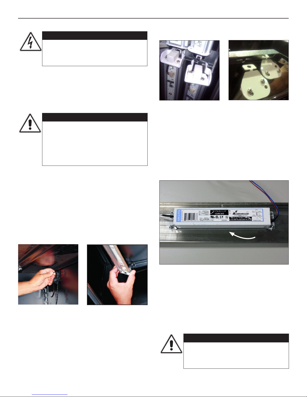
1. Remove the LED luminaires from the reflector.
2. Remove screws along length of the reflector and care-
fully remove the reflector. Power supplies will now be
visible (Fig. 12).
3. To replace reflector, reverse the procedure. Insert
reflector in front channel, lift into place, then replace
the screws in the reflector.
POWER SUPPLY ACCESS
Hillphoenix cases are equipped with LED luminaires. LED
power supplies operate both the canopy lights and shelf
lights and are located in the electrical junction box beneath
the case. An ON/OFF switch is located in the upper left-
hand corner of the lighting assembly.
Once cases have been properly positioned in the store and
an electrician has connected the lighting circuit, the lights
may be turned on to verify that they are connected and
functioning properly.
To ensure peak performance, run the lighting systems only
when the store climate control is on and case refrigeration
is started. NOTE: it is highly recommended that the
ambient store temperature not exceed 80°F.
LIGHTING & POWER SUPPLIES
CAUTION!
Never replace a 24V DC power supply
with a T-8 or T-5 ballast, since ballasts
use alternating current (AC) and operate
at a much higher voltage than is used by
this LED system. Doing so will damage
the LED system and increases the chance
of safety issues/injury.
CAUTION!
Using improper DC power supplies may
damage the luminaires, resulting in sub-
standard operation and increased chanc-
es of safety issues/injury.
DANGER!
SHOCK HAZARD
Always disconnect power to case when
servicing or cleaning. Failure to do so
may result in serious injury or death.
Fig. 12 Clear view of the power supply once the light reflector is
removed.
POWER
SUPPLY
1. Unplug the LED luminaire (Fig. 8).
2. Pinching the latching clips inward at the ends of the lu-
minaire, rotate luminaire down at each end until hooks
are free, then remove (Fig. 9).
3. To install the new luminaire, place hook into shelf roll at
shelf front and rotate rear of luminaire toward the shelf.
4. Depress the rear clip so that luminaire can finish rota-
tion and until clip engages the shelf bracket.
REPLACING SHELF LED LUMINAIRES
REPLACING NON-SHELF LED LUMINAIRES
Fig. 9 Remove the old LED
luminaire.
Fig. 8 Unplug the LED lumi-
naire.
Fig. 11 Slide the other end to
the opening in the sheet metal
and disengage.
Fig. 10 Squeeze the latching
clips and pull the luminaire
free.
1. Squeeze plastic clips on the 4-pin connector at the end
of the luminaire, then pull free of the receptacle (Fig.
10).
2. At the other end, slide the luminaire to the opening and
disengage from the metal housing slot (Fig. 11).
3. Reverse the previous steps to install the new luminaire.
7

Fig. 13 Airflow
RETURN
AIR
DISCHARGE
AIR
LOAD
LIMIT
Fig. 14 Obtain pressure and temperature readings
SUCTION
LINE TEMP
READING
TXV
BULB
SUCTION
PRESSURE
READING
AIR FLOW & PRODUCT LOAD
It is important that you do not overload the food product dis-
play so that it impinges on the air ow pattern - overloading
will cause malfunction and the loss of proper temperature
levels, particularly when discharge and return air sections
are covered. Please keep products within the load limit line
shown on the diagram below (Fig. 13).
DEFROST & TEMPERATURE CONTROLS
Hillphoenix cases utilize electric, hot gas, or timed-off
defrost. The primary components used for the defrost
cycle are the various defrost termination sensors, which
work to terminate the defrost cycle in the case. These
controls may include 1) a Klixon® thermostat, 2) a sensor
probe, or 3) a dial-type thermostat with sensor bulb (the
thermostat will always be mounted with the electrical con-
trols of the case - i.e., in the electrical junction box, in the
electrical raceway, etc.).
If electric defrost is used, the defrost termination sensor
will be located either behind the rear baffle or mounted to
the coil. If hot gas defrost is used, the defrost termination
sensor will be mounted to the dump line - the sensor
should always be mounted on the coil-side of the check
valve or solenoid valve. Finally, if timed-off defrost is used,
the refrigeration cycle is simply turned off by the case con-
trols for a specified amount of time; therefore, there are
generally no active defrost components utilized.
The discharge air probe monitors the temperature of the
discharge air and may be used as the defrost termination
sensor. The probe can generally be found behind the rear
baffle, in the upper baffle, or in front of the honeycomb.
NOTE: if the discharge air probe is used for defrost
termination, none of the termination sensors listed
earlier will be installed in the case.
For more detailed information on suggested defrost times
and settings, see Appendix A. Further adjustments may
be required depending on store conditions.
DETERMINING SUPERHEAT
To identify proper superheat settings, complete the follow-
ing:
1. Obtain suction pressure from access port; obtain suc-
tion line temperature from area near TXV bulb at the
outlet of evaporator coil (Fig. 14).
2. Using the suction pressure reading, convert pressure
to temperature using temperature pressure chart (see
Appendix C).
3. Finally, subtract the converted temperature reading
from the actual temperature reading for superheat set-
ting.
AIRFLOW, DEFROST & TEMPERATURE CONTROLS
AIR FLOW
8

CASE CLEANING
A periodic cleaning schedule should be established to
maintain proper sanitation, insure maximum operating ef-
ficiency, and avoid the corrosive action of food fluids on
metal parts that are left on for long periods of time. We
recommend cleaning once a week. Further suggestions
for case cleaning include the following:
• To avoid shock hazard, be sure all electrical power is
turned off before cleaning. In some installations, more
than one disconnect switch may have to be turned off
to completely de-energize the case.
• All surfaces pitch downward to a deep-drawn drain
trough, funneling liquids to the front of the case where
the waste outlet is located for easy access. Check the
waste outlet to insure it is not clogged before starting
the cleaning process and avoid introducing water fast-
er than the case drain can carry it away.
• To clean the LED luminaires, shut off the lights in the
case, then wipe the luminaires down with a soft, damp
cloth. Avoid using harsh or abrasive cleaners as they
may damage the lights. Be certain that the luminaires
are completely dry before re-energizing.
• If any potentially harmful cleaners are used, be cer-
tain to provide a temporary separator (e.g., cardboard,
plastic wrap, etc.) between those cases that are being
cleaned and those that may still contain product.
• Avoid spraying any cleaning liquids directly on the
electrical connections.
• Allow cases to be turned off long enough to clean any
frost or ice from coil and pans.
• Remove kickplate and clean underneath the case with
a broom and a long-handled mop. Use warm water
and a disinfecting cleaning solution when cleaning un-
derneath the cases.
Fig. 16 Single-piece fan plenum and coil cover
SINGLE PIECE FAN
PLENUM SWINGS
UP FOR EASY
CLEANING
FAN
PLENUM
COIL
FANS & CASE MAINTENANCE
FANS
The evaporator fans are equipped with 16-watt fan motors.
Motors have a counter-clockwise rotation when viewed
from the shaft end.
The fan blades are 8” in diameter and the fan blade pitch
is set during the assembly process. It is important that the
blade pitch be maintained as specified. Do not attempt a
field modification by altering the blades.
Fan motors may be changed with an easy two-step pro-
cess (Fig. 15) without lifting up the plenum, thereby avoid-
ing the necessity to unload the entire product display to
make a change:
1. Unplug the fan motor, easily accessible outside the
plenum. Push cord back through plenum opening.
2. Remove fasteners, then lift out the entire fan basket.
Reverse procedure when re-installing fan basket.
2
Fig. 15 Fan basket
1
CAUTION!
Exercise extreme caution when working in
a case with the coil cover removed. The
coil contains many sharp edges that can
cause severe cuts to the hands and arms.
ATTENTION!
Power cord must be pushed back through
the plenum opening before removing the
fan basket. Failure to do so may result in
damage to the power cord.
DANGER!
SHOCK HAZARD
Always disconnect power to case when
servicing or cleaning. Failure to do so
may result in serious injury or death.
9

A1 - A2 .......................................................................................................... 3NDML-NRG ELECTRICAL DATA & CASE DIMENSIONS
B1 - B2 ................................................................................................................................................................... ELECTRICAL WIRING
C1 ................................................................................................................................ SPORLAN PRESSURE-TEMPERATURE CHART
D1 - D5 ............................................................................................................................................ SEISMIC BRACKET INSTALLATION
APPENDIX 11
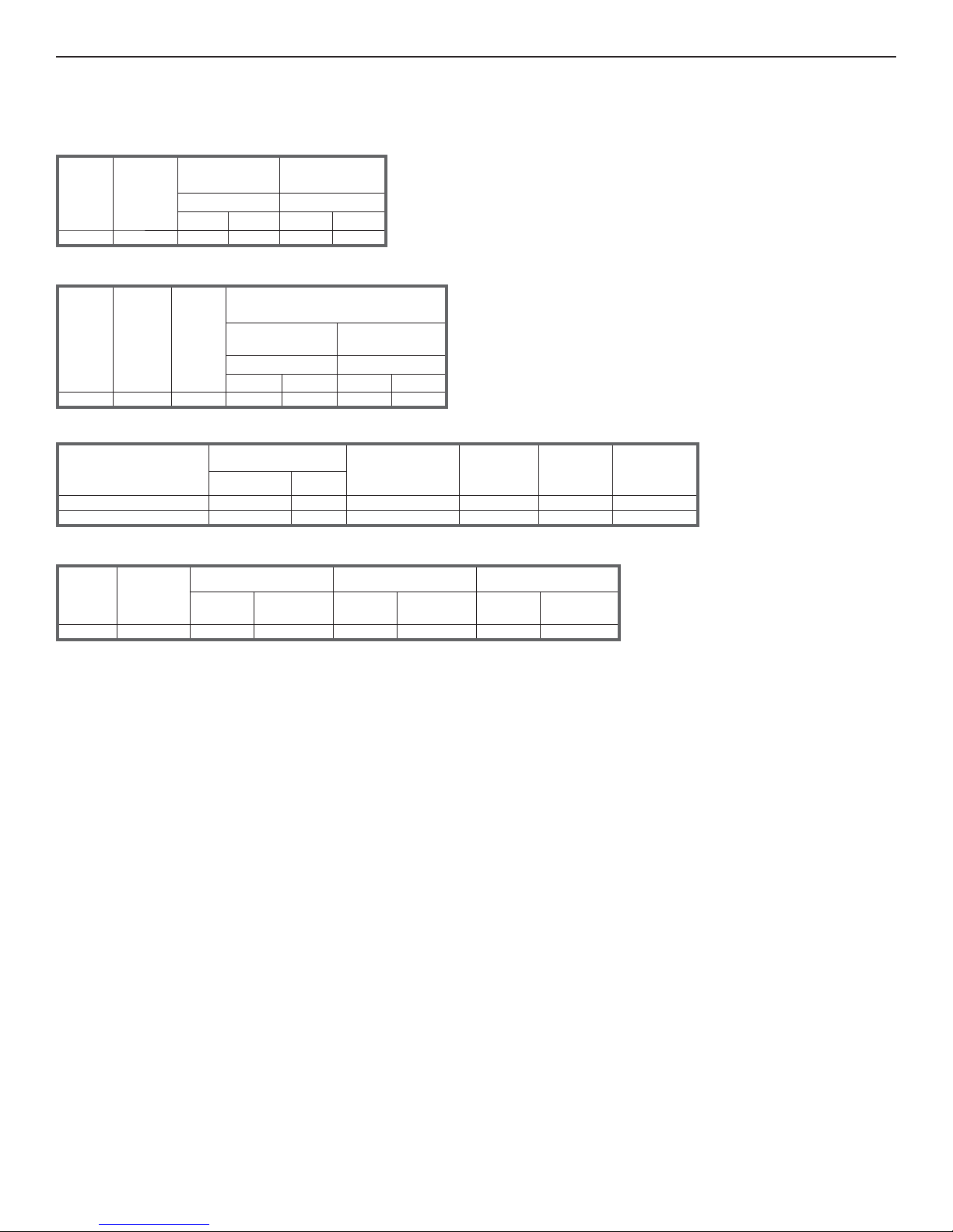
3NDML-NRG
ELECTRICAL DATA
09/13
Lighting Data
Case
Length
Lights
Per Row
Light
Length
Clearvoyant LED Lighting
(Per Light Row)
Standard Power
(Cornice or Shelf)
High Power
(Cornice)
120 Volts 120 Volts
Amps Watts Amps Watts
6' 2 3' 0.14 16.6 0.25 29.8
Electrical Data
Case
Length
Fans
Per Case
High Effi ciency
Fans
Anti-Condensate
Heaters
120 Volts 120 Volts
Amps Watts Amps Watts
6' 2 0.38 43 - - -1- - -
Defrost Controls
Defrosts
Per Day
Run-Off
Time (min)
Electric Defrost Timed-Off Defrost Hot Gas Defrost
Fail-Safe
(min)
Termination
Temp (°F)
Fail-Safe
(min)
Termination
Temp (°F)
Fail-Safe
(min)
Termination
Temp (°F)
6 6 - 8 - - - - - - 42 42 - - - - - -
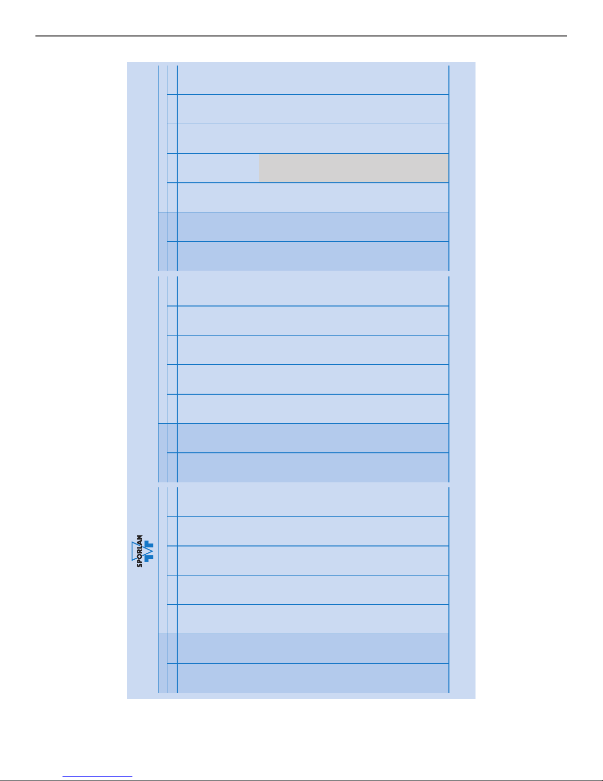
Guidelines & Control Settings
Multi-Deck Merchandiser with Synerg-E
™
4', 6', 8' & 12' (Beverage / Dairy / Deli / Produce)
3NDML-NR
G
Application
2BTUH/ft Superheat
Set Point @ Bulb
(°F)
Evaporator3
(°F)
Discharge4
Air
(°F)
Discharge5
Air Velocity
(FPM)Conventional Parallel
Dairy / Deli / Cut Produce 1177 1232 6 - 8 28 34 350
Produce / Beverage 1059 1091 6 - 8 32 37 350
1 NOTE: "- - -" indicates that feature is not an option on this case model.
2 BTUH/ft notes:
- Listed BTUH/ft indicate unlighted shelves. For LED lighting, add 36 BTUH per 4' lighted shelf and 27 BTUH per 3' lighted shelf to determine Total Lighting BTUH Load, then divide the
Total Lighting BTUH Load by the length of the case. For T8 lighted shelves (see Appendix D) and 3rd row lighting, add 92 BTUH per 4' lighted shelf and 69 BTUH per 3' lighted shelf to
determine Total Lighting BTUH Load, then divide the Total Lighting BTUH Load by the length of the case.
- Add 132 BTUH/ft when aftermarket merchandising accessories are utilized to determine the total BTUH load.
3 Listed evaporator temperature indicates unlighted shelves. For lighted shelves and/or aftermarket merchandising accessories, reduce the listed evaporator temperature by 2°F.
4 Conventional Discharge Air Control – Recommended Settings: Cut-In Temp = Discharge Air + 2°F; Cut-Out Temp = Discharge Air - 2°F
5 Average discharge air velocity at peak of defrost.
A1

CASE DIMENSIONS
09/13
NOTES:
* : STUB-UP AREA
** : RECOMMENDED STUP-UP CENTERLINE FOR ELECTRICAL AND HUB DRAINS
ENDS ADD APPROXIMATELY 1" TO CASE HEIGHT
WIRING TO THE TOP ADDS APPROXIMATELY 4" TO CASE HEIGHT
A 2" MINIMUM AIR GAP IS REQUIRED BETWEEN THE REAR OF THE CASE AND A WALL
BACK PANELS ADD APPROXIMATELY 1" TO THE REAR OF THE CASE
SUCTION LINE 7/8",
LIQUID LINE WITH HOT GAS DEFROST 1/2"
AVAILABLE SHELF SIZES: 10", 12", 14", 16", 18", 20", 22" & 24"
DASHED LINES SIGNIFY AREA INSIDE THE BASE RAIL BEHIND KICK PLATE
8 3/4 in
[22.2 cm]
72 in [182.9 cm]
A
B
C
FRONT OF CASE
1 1/2" PVC DRAIN
CONNECTION KICK PLATE
LOCATION
4' CASE
ONLY
62 in
[157.5 cm]
14 3/4 in
[37.5 cm]
40 1/4 in
[102.3 cm]
(Dh)
25 5/8 in [65.1 cm]
9 3/8 in [23.9 cm]
35 7/8 in [91.0 cm]
24 1/4 in [61.5 cm]
33 5/8 in [85.4 cm]
LOAD LIMIT
LINE
4 1/8 in
[10.5 cm]
COIL PLENUM
CLASSIC 2
STANDARD FRONT
L
C
72 in [182.9 cm] (6' CASE)
44 1/2 in
[112.9 cm]
BASE FRAME
ELECTRICAL
JUNCTION BOX
(WIRING PER
LOCAL CODES)
REFRIGERATION
31 in
[78.8 cm]
23 1/2 in
[59.5 cm]
30 1/8 in
[76.6 cm] **
23 1/8 in
[58.9 cm]
26 3/4 in
[67.9 cm]
35 7/8 in
[91.0 cm] 36 3/4 in
[93.4 cm]
7/8 in [2.4 cm]
26 3/4 in [67.9 cm] 6 7/8 in [17.4 cm]
35 in [89.0 cm]
36 3/4 in [93.4 cm]
3NDML Base Frame Structure
Case Length
72" 3/8" 34* 67 5/8"
A B C
* Riser Location
Multi-Deck Merchandiser with Synerg-E™
4', 6', 8' & 12' (Beverage / Dairy / Deli / Produce)
3NDML-NRG
A2
ATTENTION
ELECTRICIAN
:FOR SAFETY AND CODE
COMPLIANCE GROUND
FIXTURE AT TIME OF
INSTALLATION
:CAUTION
RISK OF ELECTRIC
SHOCK. MORE THAN ONE
POWER-SUPPLY.
DISCONNECT
ALL POWER-SUPPLIES
BEFORE SERVICING.
P901598E - R4
BLACK WHITE BLUE RED YELLOW PURPLE ORANGE
WIRE IDENTIFICATION
DEFROST HEATERS (1-PHASE)
DEFROST HEATERS (3-PHASE)
ANTI-CONDENSATE HEATERS
AISLE WARMER
DRAIN HEATER
PRIMARY FANS
SECONDARY FANS
AMBIENT FANS
LIGHTS
BELL
TEMPERATURE CONTROL
DEFROST TERMINATION CONTROL
DEFROST SAFETY CUT-OUT CONTROL
LIQUID LINE SOLENOID
SUCTION LINE SOLENOID
CASE/CONTROLLER POWER
TRANSFORMER
CAPACITOR
RECEPTACLE
SYSTEM NEUTRAL (3-PHASE)
POWER CORD (SELF-CONTAINED)
SERVICE LIGHT (HI-PRESSURE)
HIGH PRESSURE SWITCH
DUAL PRESSURE SWITCH
CONDENSING UNIT POWER
CONDENSING UNIT FAN
1,2
L1 L3 L2
1314
16 15
18 17
10 9
36 37
4 3 40
56
78
12 11
60,62
19,20
22 21 23
28 27 29
3130
3938
4142
24 25
34 35
3332
N
58 57
53,54
49,50
51,52
4748
45 46
44 220V
IG RECEPTACLE
GFI RECEPTACLE
HUMIDIFIER
26 43
56 55
70 71
GREEN
REFRIGERATED PAN SOLENOID
REFRIGERATED PAN BYPASS SOLENOID
AIR HEATER DEFROST SOLENOID
AIR DEFROST FAN
MAIN SECONDARY FLUID SOLENOID
SECONDARY COOLANT PUMP
GROUND TO EXTERIOR/FRAME
GROUND TO INTERIOR LINER
GROUND TO JUNCTION BOX
75
77
79
81
83
85
6465
6667
6869
72
73
74 59
76 61
65 220V
73 220V
GROUND TO LIGHTS 97
67 220V
69 220V
TANK FLUSH SOLENOID
MISTING SOLENOID
DRIP DOWN TIMER
REAR STORAGE BOX FANS
87 220V
89 220V
94
90
88
86
87
89
95
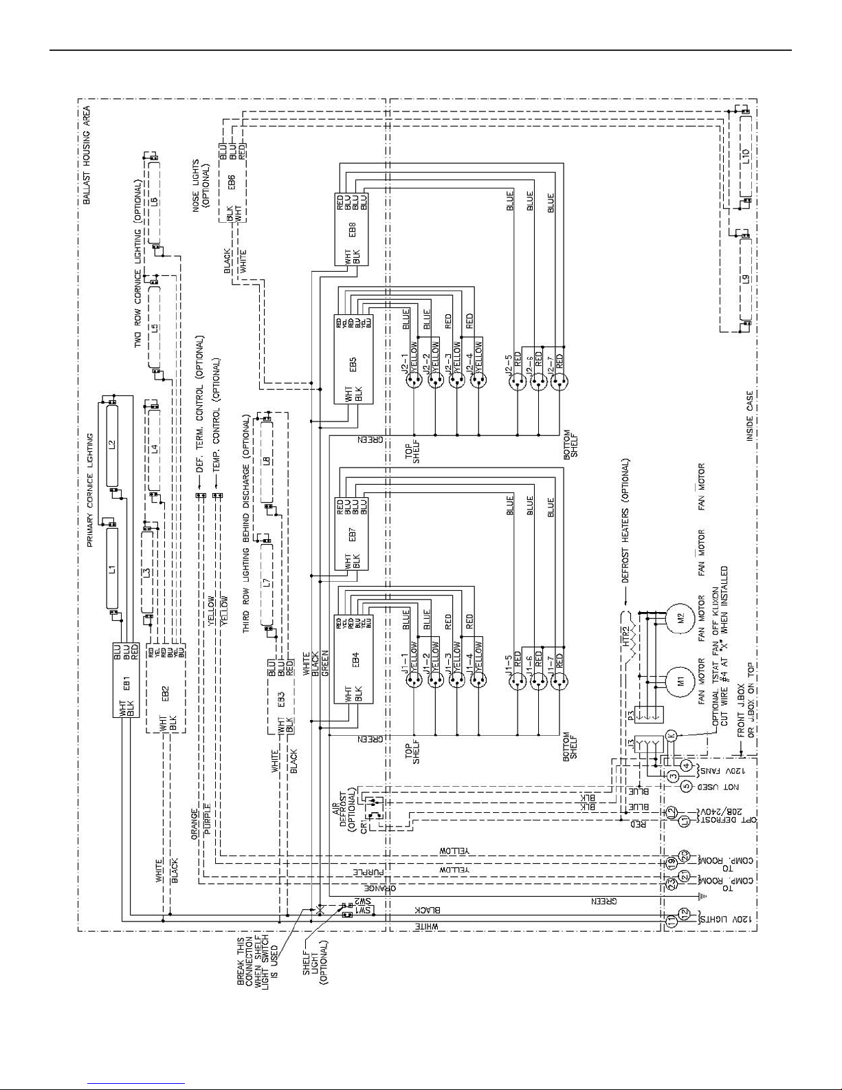
WIRE ID
WIRING IDENTIFICATION
B1
BLUE
WHITE
BLACK
3NDML
WIRING DIAGRAM B2
TEMPERATURE PRESSURE CHART - at sea level
To determine subcooling for R-404A use BUBBLE POINT values (Temperatures above 50°F — Gray Background); to determine superheat for R-404A, use DEW POINT values (Temperatures 50°F and below).
** = exceeds critical temperature
Vacuum-Inches of Mercury
Bold Italic Figures
Pressure-Pounds Per
Square Inch Gauge
FORM IC-11-09 COPYRIGHT 2009 BY SPORLAN VALVE COMPANY, WASHINGTON, MO 63090 Printed in U.S.A.
TEMPERATURE REFRIGERANT (SPORLAN CODE)
(°F) (°C) 134a (J) 404A (S) 507 (P) 717 (A) 744 - CO2
-60 -51.1 21.8 7.3 5.8 18.6 79.9
-55 -48.3 20.3 3.9 2.2 16.6 91.1
-50 -45.6 18.7 0.1 0.9 14.3 103.4
-45 -42.8 16.9 2.0 3.0 11.7 116.6
-40 -40.0 14.8 4.3 5.4 8.8 131.0
-35 -37.2 12.5 6.8 8.1 5.4 146.5
-30 -34.4 9.8 9.6 11.0 1.6 163.1
-25 -31.7 6.9 12.7 14.1 1.3 181.0
-20 -28.9 3.7 16.0 17.6 3.6 200.2
-18 -27.8 2.3 17.4 19.1 4.6 208.3
-16 -26.7 0.8 18.9 20.6 5.6 216.5
-14 -25.6 0.4 20.4 22.2 6.7 225.0
-12 -24.4 1.1 22.0 23.8 7.8 233.8
-10 -23.3 1.9 23.6 25.5 9.0 242.7
-8 -22.2 2.8 25.3 27.3 10.3 251.9
-6 -21.1 3.6 27.0 29.1 11.5 261.3
-4 -20.0 4.6 28.8 30.9 12.9 271.0
-2 -18.9 5.5 30.7 32.8 14.3 280.9
0 -17.8 6.5 32.6 34.8 15.7 291.0
1 -17.2 7.0 33.6 35.8 16.4 296.2
2 -16.7 7.5 34.6 36.9 17.2 301.5
3 -16.1 8.0 35.6 37.9 18.0 306.8
4 -15.6 8.5 36.6 39.0 18.8 312.1
5 -15.0 9.1 37.7 40.1 19.6 317.6
6 -14.4 9.6 38.7 41.1 20.4 323.1
7 -13.9 10.2 39.8 42.3 21.2 328.6
8 -13.3 10.8 40.9 43.4 22.1 334.2
9 -12.8 11.3 42.0 44.5 22.9 339.9
10 -12.2 11.9 43.1 45.7 23.8 345.7
11 -11.7 12.5 44.3 46.9 24.7 351.5
TEMPERATURE REFRIGERANT (SPORLAN CODE)
(°F) (°C) 134a (J) 404A (S) 507 (P) 717 (A) 744 - CO2
12 -11.1 13.1 45.4 48.1 25.6 357.4
13 -10.6 13.8 46.6 49.3 26.5 363.4
14 -10.0 14.4 47.8 50.5 27.5 369.5
15 -9.4 15.0 49.0 51.8 28.4 375.6
16 -8.9 15.7 50.2 53.0 29.4 381.8
17 -8.3 16.4 51.5 54.3 30.4 388.0
18 -7.8 17.0 52.7 55.6 31.4 394.3
19 -7.2 17.7 54.0 56.9 32.4 400.7
20 -6.7 18.4 55.3 58.3 33.5 407.2
21 -6.1 19.1 56.6 59.6 34.6 413.8
22 -5.6 19.9 58.0 61.0 35.7 420.4
23 -5.0 20.6 59.3 62.4 36.8 427.1
24 -4.4 21.3 60.7 63.8 37.9 433.8
25 -3.9 22.1 62.1 65.3 39.0 440.7
26 -3.3 22.9 63.5 66.7 40.2 447.6
27 -2.8 23.7 64.9 68.2 41.4 454.6
28 -2.2 24.5 66.4 69.7 42.6 461.7
29 -1.7 25.3 67.8 71.2 43.8 468.8
30 -1.1 26.1 69.3 72.7 45.0 476.1
31 -0.6 26.9 70.8 74.3 46.3 483.4
32 0.0 27.8 72.4 75.9 47.6 490.8
33 0.6 28.6 73.9 77.5 48.9 498.3
34 1.1 29.5 75.5 79.1 50.2 505.8
35 1.7 30.4 77.1 80.7 51.6 513.4
36 2.2 31.3 78.7 82.4 52.9 521.2
37 2.8 32.2 80.3 84.1 54.3 529.0
38 3.3 33.1 82.0 85.8 55.7 536.9
39 3.9 34.1 83.7 87.5 57.2 544.8
40 4.4 35.0 85.4 89.2 58.6 552.9
41 5.0 36.0 87.1 91.0 60.1 561.0
TEMPERATURE REFRIGERANT (SPORLAN CODE)
(°F) (°C) 134a (J) 404A (S) 507 (P) 717 (A) 744 - CO2
42 5.6 37.0 88.8 92.8 61.6 569.3
43 6.1 38.0 90.6 94.6 63.1 577.6
44 6.7 39.0 92.4 96.5 64.7 586.0
45 7.2 40.1 94.2 98.3 66.3 594.5
46 7.8 41.1 96.0 100.2 67.9 603.1
47 8.3 42.2 97.9 102.1 69.5 611.7
48 8.9 43.2 99.8 104.1 71.1 620.5
49 9.4 44.3 101.7 106.0 72.8 629.3
50 10.0 45.4 103.6 108.0 74.5 638.3
55 12.8 51.2 115.3 118.3 83.4 684.4
60 15.6 57.4 126.0 129.2 92.9 733.1
65 18.3 64.0 137.3 140.7 103.2 784.2
70 21.1 71.1 149.3 153.0 114.2 838.1
75 23.9 78.7 162.0 165.9 125.9 894.9
80 26.7 86.7 175.4 179.6 138.4 954.9
85 29.4 95.2 189.5 194.1 151.8 1018
90 32.2 104.3 204.5 209.3 166.1 **
95 35.0 113.9 220.2 225.4 181.2 **
100 37.8 124.2 236.8 242.3 197.3 **
105 40.6 135.0 254.2 260.1 214.4 **
110 43.3 146.4 272.5 278.8 232.5 **
115 46.1 158.4 291.8 298.5 251.6 **
120 48.9 171.2 312.1 319.2 271.9 **
125 51.7 184.6 333.3 340.9 293.3 **
130 54.4 198.7 355.6 363.8 315.8 **
135 57.2 213.6 379.1 387.8 339.6 **
140 60.0 229.2 403.7 413.0 364.7 **
145 62.8 245.7 429.6 439.5 391.0 **
150 65.6 262.9 456.8 467.4 418.7 **
155 68.3 281.0 485.5 497.0 447.8 **
SPORLAN PRESSURE–TEMPERATURE CHART
C1
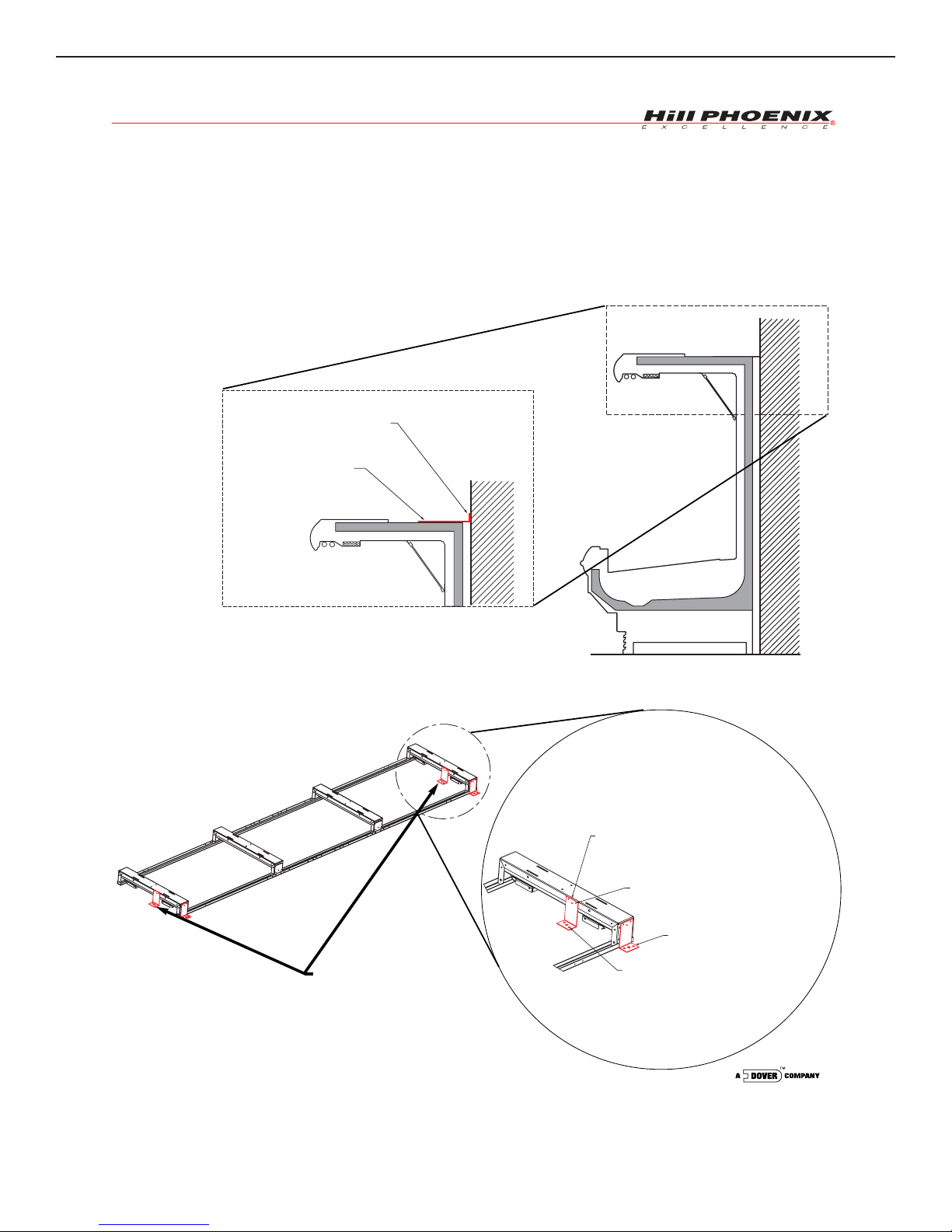
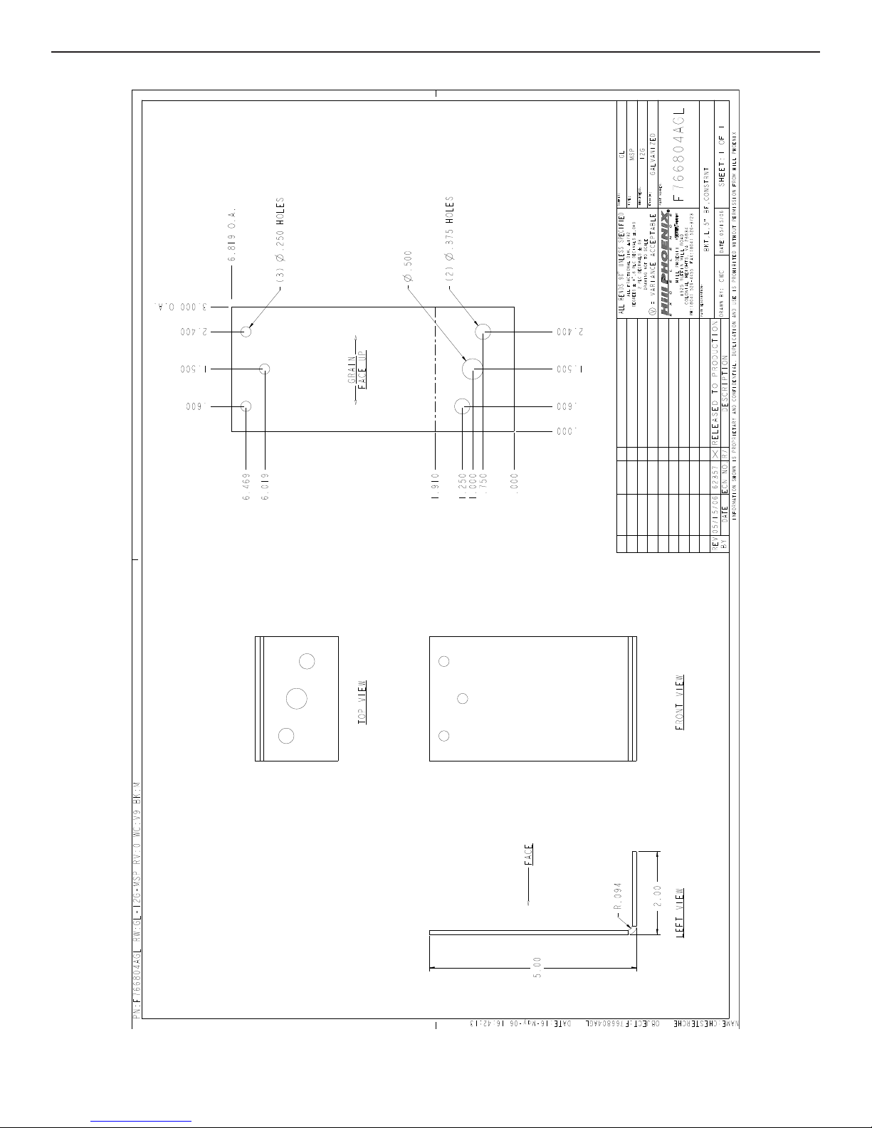
CONSTRAINT BRACKET INSTALLATION
11/05
The case constraint brackets can be installed
in 2 ways. Option 1 can be used on multi-deck cases
and uses an “L” bracket to attach the case to a vertical
wall, as shown below. Option 2 can be used on multi-
deck cases or on cases that do not have a canopy.
Attach the “L” brackets to the base frames in either of
the locations shown below. Brackets are available for
all base frame heights.
CONSTRAINT BRACKET
ATTACH TO TOP OF CASE
USE (3) #10 SELF TAPPING
SCREWS
ATTACK BRACKET TO WALL
USE (1) 0.5"
OR (2) 0.375" ANCHORS
BASE FRAME CONSTRAINT BRACKET - 2 PER CASE
(BRACKET SHOWN HERE IS FOR A 5" TALL BASE FRAME,
CONSTRAINT BRACKETS ARE ALSO AVAILABLE
FOR ALL BASE FRAME HEIGHTS
USE (3) #10 SELF DRILLING / SELF TAPPING SCREWS
FOR ATTACHMENT TO THE BASE FRAME
ALTERNATE LOCATION
(BACK OF CASE)
USE (1) 0.5" OR (2) 0.375"
ANCHOR(S) FOR ATTACHMENT
TO THE STORE FLOOR
OPTION 1
OPTION 2
BRACKET CAN BE POSITIONED
ON EITHER SIDE OF THE
BASE FRAME
SEISMIC BRACKET INSTALLATION D1
SEISMIC BRACKET - 5”
D2

SEISMIC BRACKET - 7” D3
Table of contents
Other Hillphoenix Merchandiser manuals


Popular Merchandiser manuals by other brands


Hussmann
Hussmann RGSSFP Installation & operation guide

Hussmann
Hussmann IMPACT CW2U-XGE Technical data sheet

Hussmann
Hussmann FL4NX-EP Technical data sheet

Hussmann
Hussmann Impact C2-XGEP Technical data sheet

Vollrath
Vollrath RDC9136 Operator's manual

Lincat
Lincat Seal C6A/75B Installation, operating and servicing instructions


