Hillstone HAC415-120PX User manual

OMHAC415-120PX
OPERATING MANUAL
for
AC LOAD BANK
type
HAC415-120PX
issue 1
Serial No. M37091
1

OMHAC415-120PX
CONTENTS
INTRODUCTION 3
SAFETY CONSIDERATIONS 4
CONNECTION PROCEDURE 5
OPERATING INSTRUCTIONS 7
CONTROLLING THE LOAD BANK WITH THE HHC 8
SPECIFICATION 9
RATING TABLE 9
MAINTENANCE PROCEDURE 10
FAULT FINDING PROCEDURE 10
CERTIFICATE OF CONFORMITY 11
The information contained in this document is considered correct at the time of
printing and given in good faith. Hillstone Products bears no responsibility for the
accuracy of the data given or any responsibility resulting from the use of the
equipment.
Administration Address & Manufacturing Address
Unit 1&2,
Freetown Business Park,
Hudcar Lane,
Bury,
Lancashire,
BL9 6HD,
U.K.
Tel: +44(0)161 763 3100
Fax: +44(0)161 763 3158
Email: [email protected]
Web : www.hillstone.co.u
2

OMHAC415-120PX
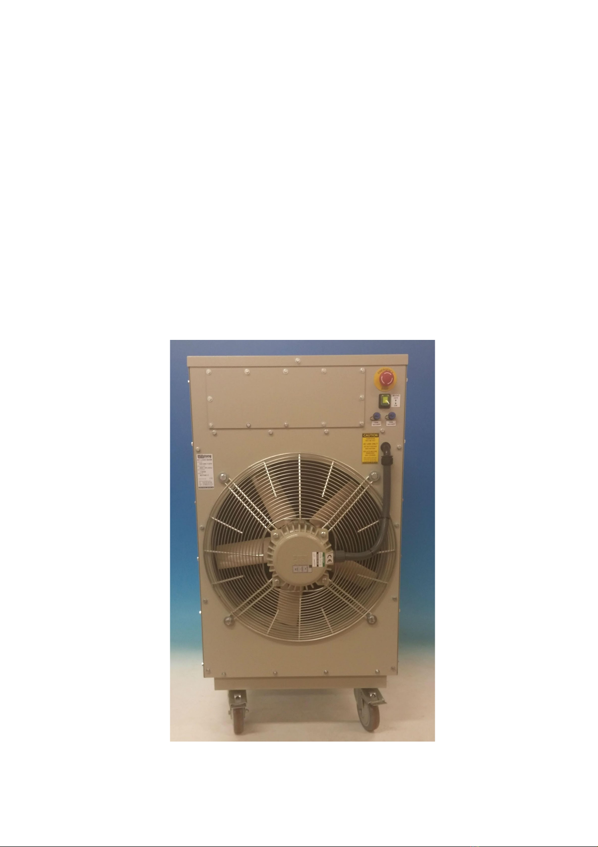
INTRODUCTION
The load bank HAC415-120PX (see fig 1) is designed for testing 415 volt, three phase,
50 Hz UPS or generators on a 4 wire, star, connection, plus earth.
The unit comprises of pre-set, force cooled, high powered resistor channels which
allows manual adjustment of the load current via a handheld controller.
The load bank is force cooled by a three phase powered cooling fan which together
with the controls are supplied from the test source.
Safety features include internal fuse protection, fan motor overload protection, control
circuit protection and auto shutoff in the event of a mains interruption.
The case is designed for indoor and outdoor use (in a well ventilated area).
Up to 8 units can be linked together and controlled from 1 handheld controller.
fig 1: photo shows a typical HAC-PX series load bank
3
OMHAC415-120PX
SAFETY CONSIDERATIONS
1. The unit should only be operated by competent electrical engineers who are
completely familiar with the operation and specification of the load bank.
2. The equipment is designed for AC operation only and therefore must not be
used on DC loads such as batteries.
3. Operators must ensure that interconnecting cables are correctly rated to carry
the required load current and adequately insulated to prevent the possibility of
electric shock.
4. When in use the load bank should be cordoned off using safety barriers.
5. The load bank should only be operated in an area with adequate ventilation.
6. Care should be taken as the exhaust air outlet will be hot.
7. Cables must be positioned away from the air exhaust
8. During operation the load bank should not be covered or positioned to restrict
air flow
9. Caution – some metal surfaces will be hot during operation
10.At the end of any test the fan should be kept running for 10 minutes on no load
to remove the residual heat from the load bank case.
fig 2: photo shows the front of a typical HAC-PX series load bank
4
OMHAC415-120PX
CONNECTION PROCEDURE
A. Ensure the power source to be tested is compatible with the load bank operating
voltage and frequency.
B. Ensure the power source is de-energised.
C. Do not attempt to operate the load bank above the maximum operating voltage.
D. Check all panel mounted ON/OFF switches are in the OFF position.
E. Connect the handheld controller to the load bank via the CAN socket.
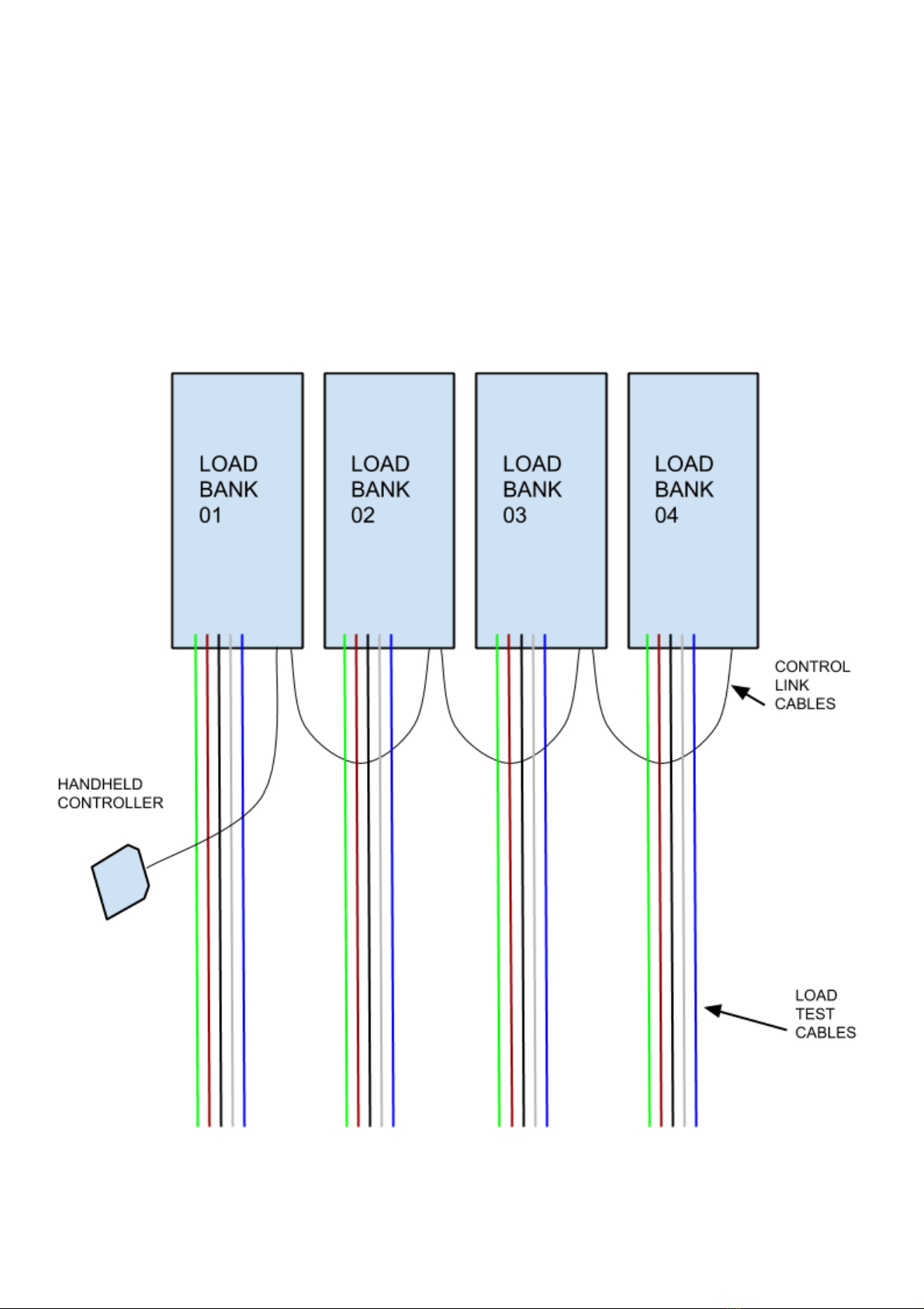
F. If multiple load banks are to be used then a control link cable is to be connected
between each additional load bank up to a maximum of 8 load banks (see fig 3).
fig 3: drawing shows 4 load banks linked together, up to 8 load banks
can be connected to 1 hand held controller
5

OMHAC415-120PX
G. Ensure the power cables are correctly connected to the power source (see fig 4)
observing correct phase rotation.
Phase Conductor - Line 1 Phase Conductor - Line 2 Phase Conductor - Line 3
Neutral Conductor Protective Conductor - Earth
fig 4: colour coding required for load bank connections
H. An undrilled gland plate is provided at the front of the load bank for cable entry.
I. Connect all test cables to the load bank (see fig 5).
J. The load connections L1, L2 & L3 are to be tightened to a torque of 32Nm and
the Neutral to a torque of 6Nm.
K. Ensure the small fan cables are still in place and secure when the connections
are completed.
fig 5: photo shows the connection points inside load bank
6

OMHAC415-120PX
OPERATING INSTRUCTIONS
Operators should read the
SAFETY CONSIDERATIONS and CONNECTION PROCEDURE
before carrying out the following operating instructions
1. Ensure all panels are in place on the load bank.
2. Ensure all panel mounted switches are in the OFF position.
3. Energise the power source from the UPS or generator to be tested.
4. Switch on the green panel mounted rocker switch (see fig 6).
5. Ensure the fan rotates in the correct direction with exhaust air being expelled
from the exhaust grill (there is also an indication arrow positioned above the fan
which shows the direction the blades should move). If the phase sequence is
incorrect causing the fan to run in the wrong direction the following procedures
should be carried out to change the phase rotation:
a) isolate the power source.
b) change over any two phase connections
c) continue the operating procedure from 1 above
fig 6: photo shows the Emergency Stop pushbutton, the Mains ON/OFF switch and
2 x CAN sockets on the front of the load bank
7
OMHAC415-120PX
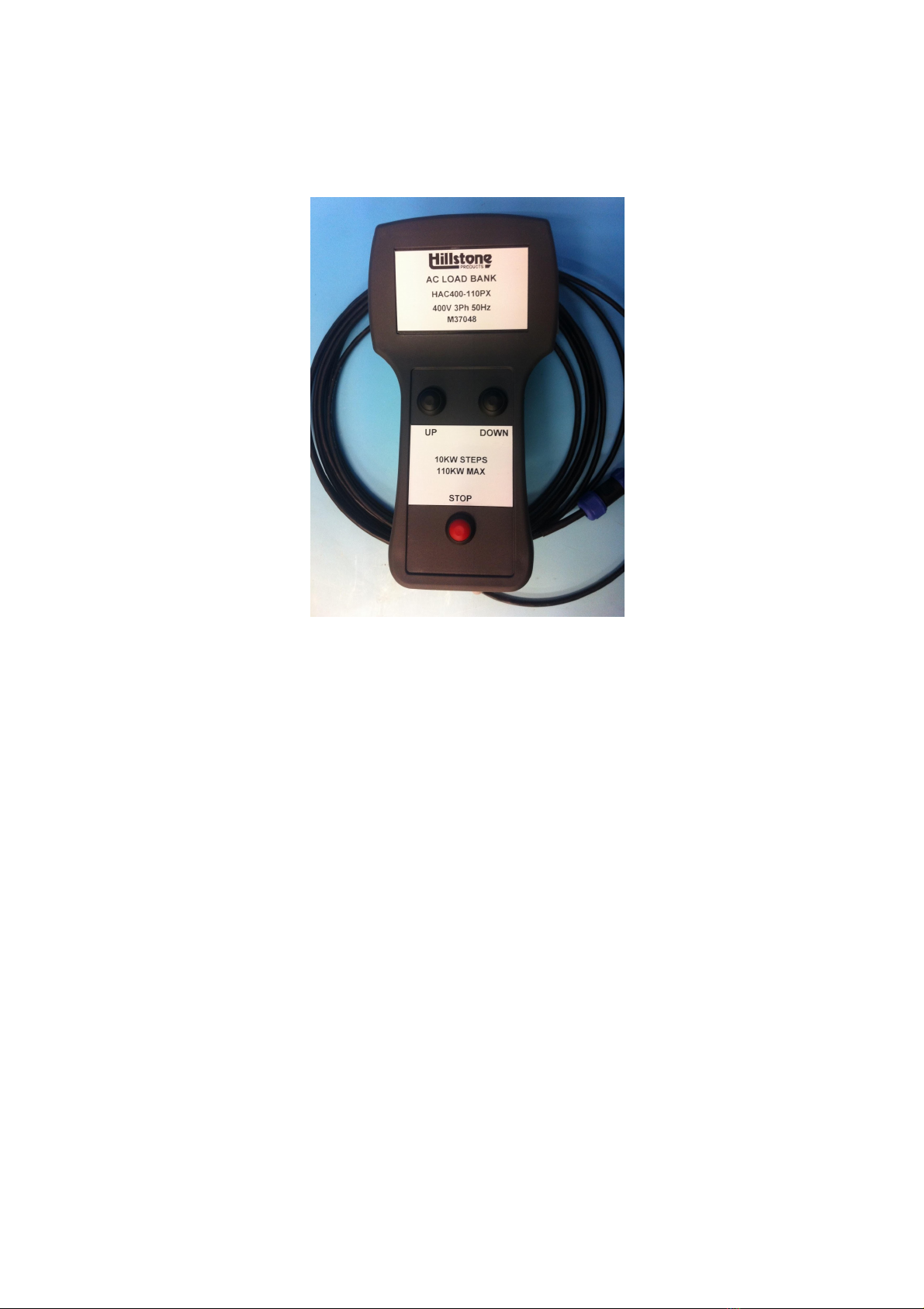
CONTROLLING THE LOAD BANK WITH THE HHC
To control the load bank the HHC hand held controller (see fig 7) is used. The HHC
incorporates 3 control buttons; UP, DOWN and STOP.
fig 7: photo shows the HHC handheld controller
Select the appropriate load using the HHC hand held controller as follows;
1. Once all load banks are powered up and connected wait 10 seconds for the
controls to stabalise before pressing any buttons.
2. By pressing the UP button the load will increase on each load bank by
approximately 12kW. Each press of the UP button will increase the load of each
load bank by approximately 12kW up to a maximum of 120kW.
3. By pressing the DOWN button the load will decrease on each load bank by
approximately 12kW. Each press of the DOWN button will decrease the load of
each load bank by approximately 12kW until 0kW is achieved.
4. By pressing the STOP button all load will be removed from each load bank. The
fan(s) will remain running until the green ON/OFF switch is turned OFF. The
fan(s) should remain running for 10 minutes to allow the elements to cool.
The red EMERGENCY STOP button on the load bank can be used as an Emergency
Disconnect at any time during a load test to disconnect all load circuits and the fan
supply.
8

OMHAC415-120PX
SPECIFICATION
Type ref HAC415-120PX
Max operating voltage 415V three phase
Max current rating 171A per phase
Max power rating 123 KW three phase
Operating Frequency 50 Hertz
Connection star 4 wire, balanced load
Controller HHC
Resistor tolerance +/-7.5%
Operating ambient temperature 0 to +35 deg C
Storage ambient temperature -10 to +45 deg C
Master PCB n/a
Relay PCB HP-FETDRV-2-ISS2
PSU PCB n/a
Data Log PCB n/a
Operating ambient temperature 0 to +40 deg C
Storage ambient temperature 0 to +80 deg C
Lifting Fork Lift Pockets
Load bank dimensions Length 1140mm
Width 580mm
Height 1130mm
Weight 145kgs
RATING TABLE
HAC415-120PX Approximate Available current & power at 415V 50Hz
Channel
Approx amps @
400V 3ph
Approx watts @
400V 3ph
Fan
1.6A
600W
1
16.7A
12000W
2
29.2A
21000W
3
62.5A
45000W
4
62.5A
45000W
Total
171A
123000W
9

OMHAC415-120PX
MAINTENANCE PROCEDURES
The load bank should not require any special maintenance, however as with any
electrical equipment periodic checks should be carried out to ensure the equipment is
in a safe and satisfactory condition.
The following periodic checks are recommended on the load bank;
1. Check the inlet and outlet grills are free from obstruction.
2. Check the controls and terminals are undamaged.
3. Check the fan rotates freely without obstruction.
4. Check control and load cables are undamaged.
5. Check the castors are secure and none of the fasteners are loose.
FAULT FINDING PROCEDURES
The following fault finding procedure is intended to identify simple operational errors
and has been categorised into two possible problem areas as follows;
FAN COOLING NOT OPERATIONAL
Check the power source is available.
Check the interconnecting cable connections.
Check the fan is running in the correct direction
Check the fan motor operates.
Check for air blockage.
Check fan blades are secure to motor shaft.
LOAD BANK DOES NOT PROVIDE SUFFICIENT LOAD CURRENT
Check the power source is at the required voltage.
Has a wait period of 10 seconds elapsed from final connection and power up to
the pressing of any control buttons on the HHC.
Any faults not corrected by carrying out the above procedures may require the internal
wiring or components of the load bank to be inspected for damage.
Important Note:
Isolate the load bank from any power source before removing any covers.
Testing the load bank with the covers removed should not be carried out
as it presents a risk of injury or death by electric shock.
Repair or replacement should be carried out by the manufacturer.
10

OMHAC415-120PX
Units 1 & 2 Freetown Business Park
Hudcar Lane, Bury, Lancs.
BL9 6HD. UK
Tel:+44(0) 161 763 3100
Fax:+44(0) 161 763 3158
Certificate of Conformity
Customer Hillstone Products Ltd
Customer order number 37091
Hillstone Manufacturing ref M37091
Equipment type ref HAC415-120PX
Equipment description Load banks
Quantity supplied 1
Date of manufacture 7th / July
Note:-
This document certifies that the whole of the items detailed above have been manufactured,
tested and inspected and unless otherwise stated conform in all respects with the requirements
of the contract or order and in accordance with the following.
●Low Voltage Directive 2006/95/EC
●EMC directive 2004/108/EC:
○ BSEN61000-6-3 2007 amendments for 2011
○ BSEN61000-6-1 2007
○ BSEN61000-6-4 2007 amendments for 2011
●Hillstone Products Quality Assurance procedures ISO9001:2008
11
This manual suits for next models
1
Table of contents
Other Hillstone Test Equipment manuals


