MAHA TPS I User manual

D1 1004BA1-GB03
TPS I and III for Eurosystem
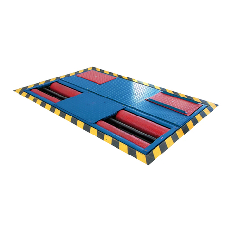
Speedometer Tester
for passenger cars, transporters and motorcycles
Original Operating Instructions

TPS I and III for Eurosystem
II D1 1004BA1-GB03
EDITION
3rd edition 09.11.2005
©MAHA GMBH&CO.KG
All rights reserved. Any reproductions of this document, partial or complete, are only allowed
with prior consent of MAHA GmbH & Co. KG.
All rights reserved in cases of patent granting or registration of design.
The contents of this version have been checked with great care. However, errors cannot be fully
excluded. Please contact MAHA should you find errors of any kind.
Subject to technical change without notice.
These instructions are intended for users with previous technical knowledge in the field of
vehicle testing technology.
MANUFACTURER
MAHA Maschinenbau Haldenwang GmbH & Co. KG.
Hoyen 20
D-87490 Haldenwang/Allgäu
Telephone: +49 (0)08374 / 5850
Telefax: +49 (0)08374 / 585499
Internet: http://www.maha.de
SERVICE
MAHA Maschinenbau Haldenwang GmbH & Co. KG.
- Service Dept. -
Hoyen 20
D-87490 Haldenwang/Allgäu
Hotline: +49 (0) 1806 624260 for brake testers, test lanes
+49 (0) 1806 624280 for lifting technology
+49 (0) 1806 624290 for dynamometers, emission testers
Service: +49 (0) 1806 624250
Telefax: +49 (0) 1806 624255

TPS I and III for Eurosystem
D1 1004BA1-GB03 III
TABLE OF CONTENTS
1Safety..........................................................................................................................1
1.1Introduction ....................................................................................................................................1
1.2Safety Regulations for Commissioning..........................................................................................1
1.3Safety Regulations during Operation.............................................................................................2
1.4Safety Regulations for Service Work.............................................................................................2
1.5Attention.........................................................................................................................................2
1.6Further Information.........................................................................................................................2
2Description.................................................................................................................3
2.1Usage, Range of Application .........................................................................................................3
2.2Installation......................................................................................................................................3
2.3Noise Emission ..............................................................................................................................3
2.4Equipment Overview......................................................................................................................4
2.5Technical Specifications ................................................................................................................4
2.5.1TPS I...............................................................................................................................4
2.5.2TPS III (Motorcycle)........................................................................................................5
3Operations .................................................................................................................7
3.1Introduction ....................................................................................................................................7
3.2Testing Procedure..........................................................................................................................7
3.2.1Speedometer Test..........................................................................................................8
3.2.2Travel Distance Test.....................................................................................................10
3.2.3Storage of Test Values.................................................................................................12
3.2.4Reviewing of Measurements........................................................................................12
3.2.5Prepare New Test.........................................................................................................12
3.3TPS I with Self-Contained Drive (optional) ..................................................................................13
3.3.1Equipment Overview.....................................................................................................13
3.3.2Manual Control Device .................................................................................................13
3.3.3Speedometer Test with Self-Contained Drive..............................................................14
3.4TPS III (Motorcycle) .....................................................................................................................15
3.4.1Speedometer Test with Self-Contained Drive..............................................................15
3.4.2Speedometer Test with Separate Drive .......................................................................16
4Maintenance & Troubleshooting............................................................................17
4.1Maintenance.................................................................................................................................17
4.2Troubleshooting ...........................................................................................................................18
TPS I and III for Eurosystem
IV D1 1004BA1-GB03

TPS I and III for Eurosystem
D1 1004BA1-GB03 1
1 Safety
1.1 Introduction
Please read the standard operating procedures and user’s manual thoroughly and carefully
before commissioning the machinery and comply with the instructions. The operating manual
should always be conveniently stored to be readily available at all times.
This operating manual is an addition to the operating manual for the testing lane Eurosystem.
All safety instructions provided in chapter 1 of these operating instructions must be complied
with.
Injury to persons incurred due to non-compliance with these operating instructions are not
covered by the product liability regulations.
MAHA is not liable for damage to the test stand and/or vehicles incurred due to non-compliance
with these operating instructions.
A warning means that instructions that are not complied with or incompletely complied with can
endanger persons.
Attention means that instructions that are not complied with or incompletely complied with can
lead to equipment damage.
Notes provide additional information.
Safety information is provided to warn about dangerous situations and help prevent damage to
equipment and injury to persons. For your own safety it is imperative that all safety regulations
included in these instructions be carefully observed.
The operating manual for the speedometer tester must be read thoroughly and completely by
the operator before commissioning.
Carefully observe all federal and international safety guidelines for work place protection.
Every user is responsible for observing all regulations which apply to his workplace and is
obliged to integrate any new regulations that may be initiated.
1.2 Safety Regulations for Commissioning
The speedometer tester may only be commissioned by MAHA Service technicians or those
authorized by MAHA as service partners.
All electrical parts of the testing machinery must be protected from moisture and humidity.
The speedometer tester may not be installed and operated in explosion endangered rooms
or wash halls.

Safety TPS I and III for Eurosystem
2D1 1004BA1-GB03
1.3 Safety Regulations during Operation
The speedometer tester may only be used and operated for its intended purpose and within
its stated performance limits.
The speedometer tester may only be operated by trained, authorized personnel.
Sudden or strong braking actions and jerky accelerations are forbidden.
Secure the vehicle with restraining straps onto the roller set!
Drive test vehicle straight onto the rollers. Front-wheel drive vehicles must maintain a
straight driving direction during the test.
The speedometer tester and the surrounding work area must be kept clean.
The test stand must be switched off when not in use and the main switch secured against
tampering with a padlock.
No persons are allowed in the speedometer danger zone. Rotating or moving parts are
dangerous. (e.g. test stand rollers).
In case of emergency turn the main switch (the EMERGENCY OFF switch) to 0.
Running vehicle engines represent potential carbon monoxide poisoning. The
operator/owner is responsible for providing for sufficient air ventilation.
1.4 Safety Regulations for Service Work
Service work such as installation, maintenance or repair work on the test stand may only be
done by MAHA service technicians or authorized service partner technicians.
All work done on electrical parts of the equipment is to be carried out by trained, qualified
electricians.
Before doing any repair- / maintenance- / set up turn off the main switch and secure against
tampering.
1.5 Attention
Never start a vehicle engine using the speedometer tester. This can lead to damage on the
test stand.
No vehicle with 4 wheel drive or automatic transmission may be tested on the speedometer
tester. This can lead to damage on both the vehicle and the test lane. Should questions arise
inquire at the responsible service representative.
No persons are allowed in the immediate vicinity of the tester while a vehicle test is in
progress.
1.6 Further Information
Avoid unnecessary strain on vehicle and test stand.
Drive the vehicle slowly onto the test stand.
Pay attention that the vehicle has sufficient ground clearance.

TPS I and III for Eurosystem
D1 1004BA1-GB03 3
2 Description
2.1 Usage, Range of Application
The speedometer tester is a roller tester for the inspection of the speedometer function of
vehicles. The speedometer tester permits the measurement of speed deviation as well as the
deviation of the mileage meter.
Passenger cars and transporters up to a total axle load of 4 t can be tested (2 t with TPS III for
motorcycles).
The recorded measuring values are transmitted to the Eurosystem communication desk and
then displayed on the screen. The storing and the reviewing of measurements is described in
the operating manual for the testing lane Eurosystem.
2.2 Installation
The test stand may only be installed and commissioned by the manufacturer's trained
authorized personnel or other qualified technicians of MAHA dealers or representatives. MAHA
instructions must be followed when installing or expanding the testing device.
The manufacturers CE conformity declaration becomes invalid when the installation is done by
qualified service technicians. MAHA is not liable for damage caused by unqualified,
unauthorized installation. Further, the manufacturers warranty also becomes invalid.
2.3 Noise Emission
The noise emission test was conducted during the speedometer test, at the highest test speed
of 150 km/h.
Test results
A-evaluated sound pressure level: 105,0 dB(A) (averaged with all measuring points, see
measuring protocol)
A-evaluated acoustic power level: 103,4 dB(A) (calculation based on DIN 45635 Part 1)
Due to the high noise in the test room, ear protection should be worn.

Description TPS I and III for Eurosystem
4D1 1004BA1-GB03
2.4 Equipment Overview
2.5 Technical Specifications
2.5.1 TPS I
TPS I TPS I with self-contained drive
Max. axle load 4 t
Testing speed 30 to 150 km/h
Weight 400 kg
Tracking width 780 to 2200 mm
Roller diameter 202 mm
Roller length 720 mm
Roller axle separation 300 mm
Dimensions roller set
(HxWxL) 220 x 580 x 2320 mm
Exit support blocking system on rear rollers
or
lifting device
Engine performance - 22 kW
Voltage 230 V / 50 Hz 400 V AC, 3/N/PE, 50 Hz
Fuse protection - 50 A
Nominal current - 40 A

TPS I and III for Eurosystem Description
D1 1004BA1-GB03 5
2.5.2 TPS III (Motorcycle)
TPS III TPS III with self-contained
drive
Max. axle load 2 t
Testing speed 30 to 150 km/h 30 to 150 km/h (*)
Cable length of
manual control device 7 m
Roller length 200 mm
Roller circumference 635 mm
Roller diameter 202 mm
Optional:
Clamping device with
side restraining rollers
mechanical (with crank handle)
pneumatic
Exit support none
Engine performance - 5,5 kW (*)
Voltage 230 V / 50 Hz 400 V AC, 3/N/PE, 50 Hz
(*) Standard version: 5,5 kW.
The speedometer tester is available with different engine performances. The maximum testing
speed depends on the engine performance.

Description TPS I and III for Eurosystem
6D1 1004BA1-GB03

TPS I and III for Eurosystem
D1 1004BA1-GB03 7
3 Operations
3.1 Introduction
Please also read chapter 4, Eurosystem PC-Program, in the operating manual for the testing
lane Eurosystem.
The second part of this chapter describes the testing procedure of a speedometer test and
distance test. The screen pictures on the right-hand side show the screens which appear during
operation. The steps listed on the left provide the user with clear explanations of procedure.
The third part provide information about the operation of a TPS I test stand with self-contained
drive (Option). The fourth part describes the operation of the TPS III (motorcycle).
The storing and the reviewing of measurements is described in the operating manual for the
testing lane Eurosystem.
3.2 Testing Procedure
In order to start the testing procedure, the
monitor must show the main menu.
The instruction line must show the following
message:
New test can begin ...
If this message does not appear press
<F8 NEW VEHICLE>.
Now the test lane is ready for a vehicle to be
driven on. When the vehicle drives onto the
individual equipment the corresponding test
screen is blended in.
Always pay attention to the messages and instructions on the instruction line during testing.
(in the description this is indicated by Instruction text).
The recorded measurement values are automatically taken over in the temporary memory and
remain there until they are stored in connection with customer/vehicle or until they are
overwritten when a new test is conducted.
The following guides the user through the automatic testing procedure step by step. Usage of
the individual screen elements and the keyboard has already been clearly explained. See the
following sections in the operating manual for the testing lane Eurosystem to refresh your
memory:
=> 4.1.3 Screen Design
=> 4.1.4 Keyboard Usage

Operations TPS I and III for Eurosystem
8D1 1004BA1-GB03
3.2.1 Speedometer Test
No vehicle with 4 wheel drive or automatic transmission may be tested on the speedometer
tester. This can lead to damage on both the vehicle and the test lane. Should questions arise
inquire at the responsible service representative.
The speedometer test can be conducted by using the keyboard or the remote control. If a
remote control is not available, a second person will be needed to perform the test.
The speedometer tester permits the measurement of the difference between the actual vehicle
speed and the speed displayed on the tachometer of the vehicle.
1 Drive onto the test stand
a. Drive the driven axle of the vehicle
slowly onto the roller set.
The vehicle must be positioned
straight and centered on the roller
set.
b. Apply the parking brake.
2 Preparations
Secure the vehicle with tightening belts
(see chapter 2).
3 Start the testing program
Accelerate the vehicle up to 5 km/h to
start the testing program.
Rotating test stand rollers are potentially dangerous! Risk of injury!
=> The following screen appears:
Accelerate the vehicle to the target value
The peak of the green arrow indicates the
target speed, the bottom indicates the
tolerance range (5 km/h). The black arrow
shows the actual speed of the vehicle.
4 Conduct the test
Accelerate the vehicle up to the indicated
target value as per vehicle speedometer.
The recorded test values will be
displayed. If the actual speed is within the
tolerance range for 3 sec., the test values
will automatically be stored.
The next target speed will be indicated.

TPS I and III for Eurosystem Operations
D1 1004BA1-GB03 9
The measuring value can also be stored by pressing the <F5> key, in order to display the next
target speed. If a remote control is not available, a second person is needed to store the value
by using the keyboard.
5 Repeat test
The test must be repeated for every
target speed as described in step 4.
The test can be aborted by pressing the
<ESC>-key.
6 Exit the test stand without lift beam
Remove the restraining straps.
Slowly exit the roller set in backward direction. The roller blocking system will be activated
and the test stand can be exitted.
Exit the test stand with lift beam
Before raising the lifting device, the restraining straps must be removed!
Press <F4> on the keyboard or on the remote control. After the vehicle is lifted, slowly exit
the roller set in forward direction.
Remove the restraining straps.
Press <F4> on the keyboard or remote control.
After the vehicle is lifted slowly exit the roller set in forward direction.
The recorded measurement values are automatically taken over in the temporary memory.
It is possible to intervene in the automatic test procedure by pressing <F5>. The measuring
values will be stored and the test procedure continues. If the test is repeated, the measuring
values in the temporary memory will be overwritten.

Operations TPS I and III for Eurosystem
10 D1 1004BA1-GB03
3.2.2 Travel Distance Test
No vehicle with 4 wheel drive or automatic transmission may be tested on the speedometer
tester. This can lead to damage on both the vehicle and the test lane. Should questions arise
inquire at the responsible service representative.
The speedometer test can be conducted by using the keyboard or the remote control. If a
remote control is not available, a second person will be needed to perform the test.
1 Drive onto the test stand
a. Drive the driven axle of the vehicle
onto the roller set.
The vehicle must be positioned
straight and centered on the roller
set.
b. Apply the parking brake.
2 Preparations
Secure the vehicle with tightening belts.
(see chapter 2).
3 Start the testing program
Accelerate the vehicle up to 5 km/h to
start the testing program.
The screen opposite appears.
Accelerate the vehicle to the target
value
Rotating test stand rollers are potentially dangerous! Risk of injury!
4 Activate the travel distance test
Press <F8> travel distance to switch to
the corresponding test mode. The screen
opposite appears.
Enter correction factor
The standard setting for the correction
factor is 100%. The correction factor
defines the relation of the tire
circumference on the road to the tire
circumference on the test stand rollers.

TPS I and III for Eurosystem Operations
D1 1004BA1-GB03 11
5 Conduct the test
a. Enter the mileage of the vehicle via
the number keys of the keyboard
or remote control.
b. Confirm with <RETURN>.
c. Accelerate the vehicle to approx. 20
km/h
Pay attention to the vehicle’s tachometer.
After a distance of 100 m is travelled
press <F5>. Repeat this process ten
times.
The recorded test values and the
average travel distance will be displayed.
6 Terminate the test
The recorded measuring values can be
called up using <F6>.
If desired, the test can be aborted with
the <F8> key.
The adjacent screen appears:
Press <ESC> to leave this screen.
7 Exit the test stand without lift beam
Remove the restraining straps.
Slowly exit the roller set in backward direction. The roller blocking system will be activated
and the test stand can be exitted.
Exit the test stand with lift beam
Before raising the lifting device, the restraining straps must be removed!
Press <F4> on the keyboard or on the remote control. After the vehicle is lifted, slowly exit
the roller set in forward direction.
Remove the restraining straps.
Press <F4> on the keyboard or remote control.
After the vehicle is lifted slowly exit the roller set in forward direction.
The recorded measurement values are automatically taken over in the temporary memory. If
the test is repeated, the measuring values in the temporary memory will be overwritten.

Operations TPS I and III for Eurosystem
12 D1 1004BA1-GB03
3.2.3 Storage of Test Values
The storage of test values is described in the operating manual for the testing lane Eurosystem
(Dok.-No. D1 E101BA1 D04):
=> Section 4.2.6 „Storage of Test Values“.
3.2.4 Reviewing of Measurements
The reviewing of test values is described in the operating manual for the testing lane
Eurosystem (Dok.-No. D1 E101BA1 D04):
=> Section 4.4 „Reviewing of Measurements“.
3.2.5 Prepare New Test
Make sure that the temporary storage is empty for beginning a new test procedure and the main
menu appears with the message:
New test can begin ...
After properly storing the test values the main menu appears automatically in test readiness. It
is also possible that the instruction line shows a different ready message or that a test has been
aborted and is to be started again from the very beginning.
Activate the following box in the main menu:
A message about test readiness appears in
the instruction line:
New test can begin ...

TPS I and III for Eurosystem Operations
D1 1004BA1-GB03 13
3.3 TPS I with Self-Contained Drive (optional)
3.3.1 Equipment Overview
ASwitch cabinet
BEmergency-off button
CMain switch
DOFF-key
EON-key
FConnection to manual control device
GManual control device
3.3.2 Manual Control Device
The manual control device is used to set the speed of the speedometer tester from 0 to 150
km/h.

Operations TPS I and III for Eurosystem
14 D1 1004BA1-GB03
3.3.3 Speedometer Test with Self-Contained Drive
No vehicle with 4 wheel drive or automatic transmission may be tested on the speedometer
tester. This can lead to damage on both the vehicle and the test lane. Should questions arise
inquire at the responsible service representative.
The speedometer test can be conducted by using the keyboard or the remote control. If a
remote control is not available, a second person will be needed to perform the test.
Switch-on / Preparations
1 Switch on main switch on switch cabinet.
2 Press ON-key. After a 30-sec. self- check, the test stand is ready for operation.
3 Drive the vehicle axle on which the speedometer is connected onto the roller set. Use
restraining straps to tie down the test vehicle at the sides.
Conducting the test
Rotating test stand rollers are potentially dangerous! Risk of injury!
1 Start the electric motor of the speedometer tester using the potentiometer of the manual
control device. Use the manual control device to adjust the speed from 0 - 150 km/.
e.g.: turn the setting regulator until the speedometer of the vehicle shows 50 km/h and press
the 50 km/h key on the manual control device.
See section 3.2.1 for the speedometer test or section 3.2.2 for the distance test.
Switch-off
1 After the test is completed, turn the setting regulator on the manual control device to 0 km/h.
2 Press OFF-key to disable the electric motor.
3 Open the clamping device completely and exit the test stand.

TPS I and III for Eurosystem Operations
D1 1004BA1-GB03 15
3.4 TPS III (Motorcycle)
3.4.1 Speedometer Test with Self-Contained Drive
The speedometer test can be conducted by using the keyboard or the remote control. If a
remote control is not available, a second person will be needed to perform the test.
Switch-on / Preparations
1 Switch on main switch on switch cabinet.
2 Press ON-key. After a 30-sec. self- check, the test stand is ready for operation.
3 Drive the front wheel of the motorcycle onto the roller set. Use restraining straps to tie down
the motorcycle at the sides.
Conducting the test
Rotating test stand rollers are potentially dangerous! Risk of injury!
1 Start the electric motor of the speedometer tester using the potentiometer of the manual
control device. Use the manual control device to adjust the speed from 0 - 150 km/.
e.g.: turn the setting regulator until the speedometer of the motorcycle shows 50 km/h and
press the 50 km/h key on the manual control device.
See section 3.2.1 for the speedometer test or section 3.2.2 for the distance test.
Switch-off
1 After the test is completed, turn the setting regulator on the manual control device to 0 km/h.
2 Press OFF-key to disable the electric motor.
3 Open the clamping device completely and exit the test stand.

Operations TPS I and III for Eurosystem
16 D1 1004BA1-GB03
3.4.2 Speedometer Test with Separate Drive
The speedometer test can be conducted by using the keyboard or the remote control. If a
remote control is not available, a second person will be needed to perform the test.
Switch-on / Preparations
1 Switch on main switch on switch cabinet.
2 Press ON-key. After a 30-sec. self- check, the test stand is ready for operation.
3 Drive the rear wheel of the motorcycle onto the roller set. Use restraining straps to tie down
the motorcycle at the sides.
Conducting the test
Rotating test stand rollers are potentially dangerous! Risk of injury!
1 Start the motor of the motorcycle. Accelerate the motorcycle until the desired test speed has
been reached and press the corresponding key on the remote control or keyboard for
storage.
See section 3.2.1 for the speedometer test or section 3.2.2 for the distance test.
Switch-off
1 If the speed falls below 5 km/h, the tester is automatically off and the testing process is
finished.
2 Wait until the rollers have come to a standstill.
3 Open the clamping device completely and exit the test stand.
This manual suits for next models
1
Table of contents
Other MAHA Test Equipment manuals