Hilltip SnowStriker 1800-VP Operating instructions

STRIKERTM
1800-VP • 2100-VP • 2250-VP
OWNER’S MANUAL AND
INSTALLATION INSTRUCTIONS
Read this manual before installing or operating the plow
CAUTION
!

SnowStriker SnowStriker
2 3
Safety instructions .....................................................3
Technical specications.................................................4
Warning and caution labels ..............................................5
Quick hitch instructions .................................................6
Joystick .............................................................7
Error codes ..........................................................8
Plow details and installation instructions ....................................9
Vehicle harness .......................................................10
Parts ...............................................................11
Plow valve electrical functions............................................12
Hydraulic schematics. . . . . . . . . . . . . . . . . . . . . . . . . . . . . . . . . . . . . . . . . . . . . . . . . . . 13
Parts - Hydraulic power pack. . . . . . . . . . . . . . . . . . . . . . . . . . . . . . . . . . . . . . . . . . . . . 14
Parts list - Hydraulic power pack ..........................................15
TABLE OF CONTENTS

SnowStriker
2 3
Observe these safety precautions
before, during and after operating the
snowplow. You can prevent injury to
persons and damage to the plow by
following these precautions.
SAFETY INSTRUCTIONS
Incorrect installation and operation can lead to serious personal injury and/or damage your
equipment and property. Note and ensure that you understand this manual and all the labels
before installing, operating or making adjustments to the snowplow.
!WARNING
Before operating snowplow:
• Read this manual before operating the
snowplow.
• Make sure that your vehicle total
weight is not exceeded beyond payload
limits.
• Inspect hydraulic components and
hoses
• Replace any damaged or worn parts,
a snowplow in need of repairs or main-
tenance should not be operated.
• Make sure the equipment is securely
and correctly mounted.
While operating snowplow:
• Make sure that bystanders keep a
safe distance (3 m) when the blade
is being operated, raised, lowered or
angled. Don’t stand between vehicle
and blade, a moving or falling blade
can cause personal injury.
• Transport speed should not exceed
70km/h
• Plowing speed should not exceed
15 km/h
Maintenance of the snowplow:
• Before removing or replacing any
electrical components, always dis-
connect the battery.
• Use a piece of cardboard or wood to
detect a suspected hose leak. Do NOT
use your hand to locate it, hydraulic
uid can damage your skin.
After operating snowplow:
• Lower the plow when vehicle is
parked.The hydraulic pressure can
change if temperature changes, caus-
ing an unexpected plow drop which
can lead to plow damage or personal
injury.
Personal safety
• To prevent accidents, secure long hair
and do not wear jewelry or necktie, only
wear tight-tting clothes while working
on your plow or vehicle.
• Protect your eyes with safety goggles to
avoid damage from battery acid, gaso-
line, dirt and dust.
!WARNING !WARNING
!WARNING !WARNING
SnowStriker SnowStriker
4 5
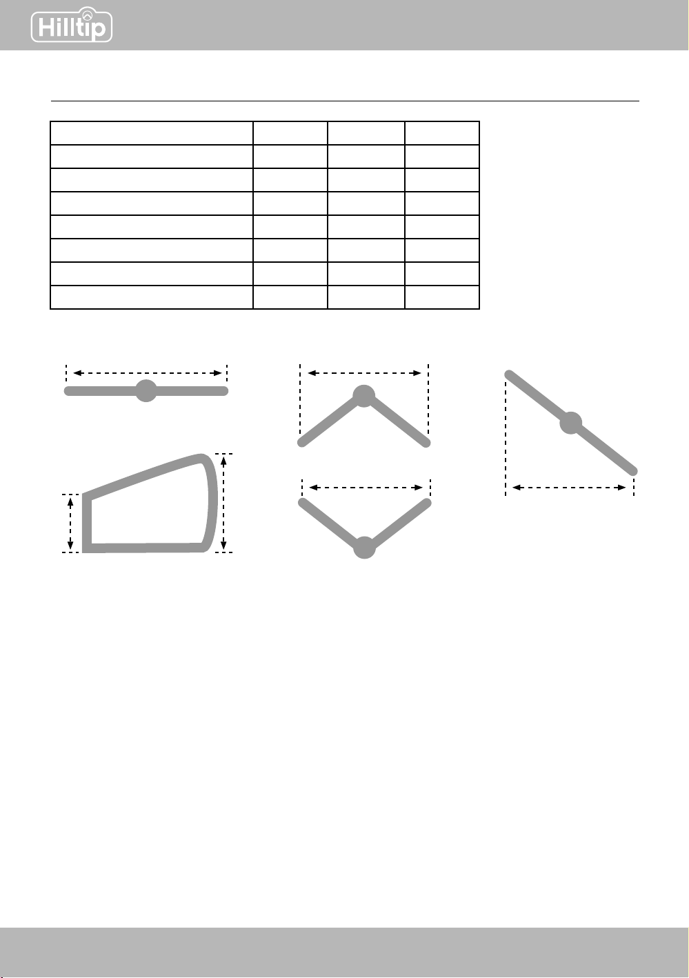
b.
c.
e.
a. d.
f.
Description 1850-VP 2100-VP 2250-VP
Width (a.) 1850 2100 2250
Height, center (b.) 550 550 550
Height, outer edge (c.) 655 670 680
Width, v-position (d.) 1600 1850 2000
Width, scoop position (e.) 1600 1850 2000
Width, windrow position (f.) 1600 1850 2000
Weight 142 kg 149 kg 155 kg
TECHNICAL SPECIFICATIONS
SnowStriker
4 5
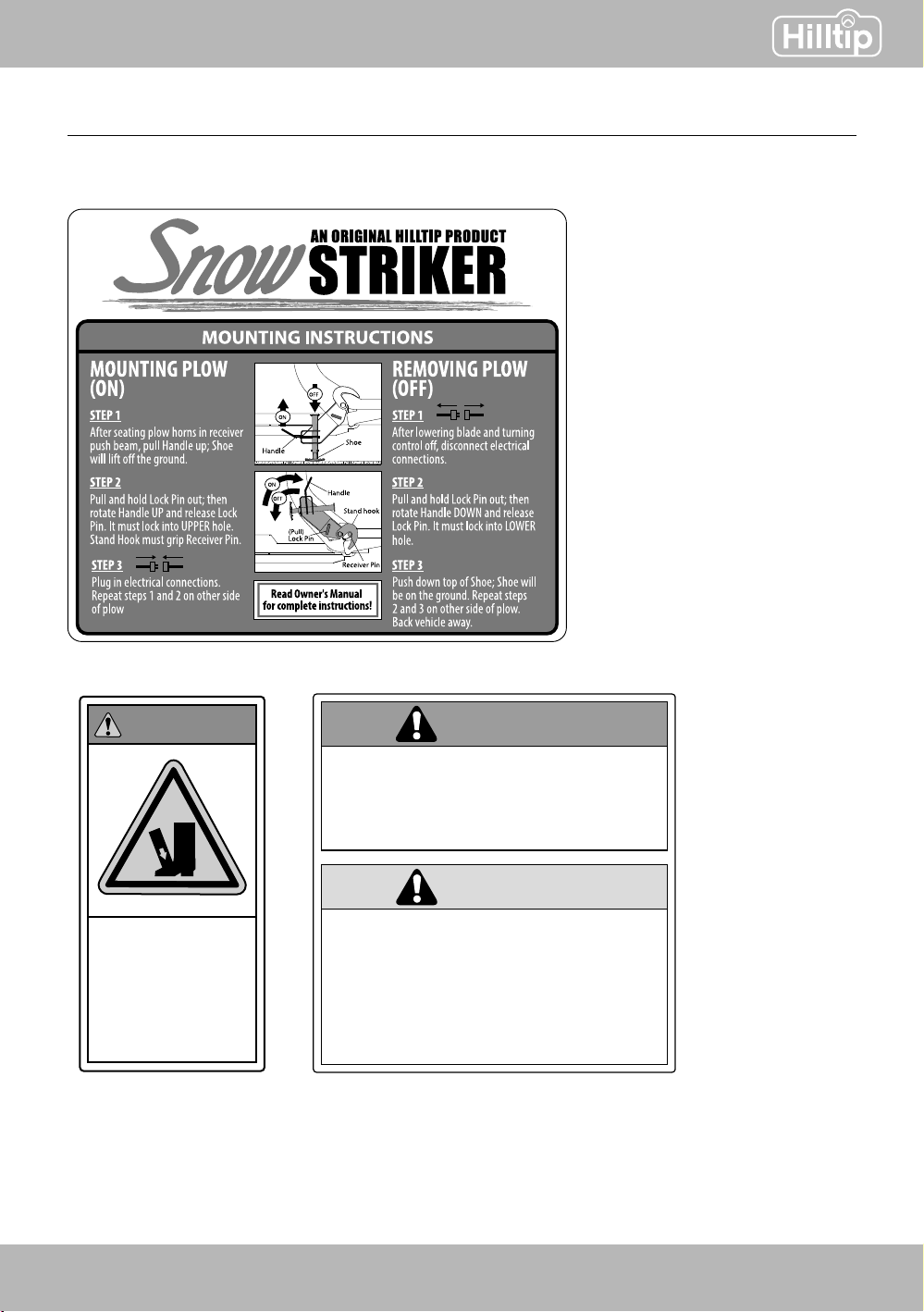
WARNING AND CAUTION LABELS
Please become familiar with these warning and caution labels on the plow.
Crush
hazard.
Keep feet
clear.
WARNING
LOWER BLADE WHEN VEHICLE IS PARKED.
DO NOT EXCEED GVWR OR GAWR INCLUDING BLADE
AND BALLAST.
REMOVE BLADE ASSEMBLY BEFORE PLACING
VEHICLE ON HOIST.
READ OWNER'S MANUAL BEFORE OPERATING OR
SERVICING SNOWPLOW.
TRANSPORT SPEED SHOULD NOT EXCEED 70 KM/H.
FURTHER REDUCE SPEED UNDER ADVERSE TRAVEL
CONDITIONS.
PLOWING SPEED SHOULD NOT EXCEED 15 KM/H.
SEE YOUR SALES OUTLET/WEB SITE FOR SPECIFIC
VEHICLE APPLICATION RECOMMENDATIONS.
WARNING
CAUTION
SnowStriker SnowStriker
6 7
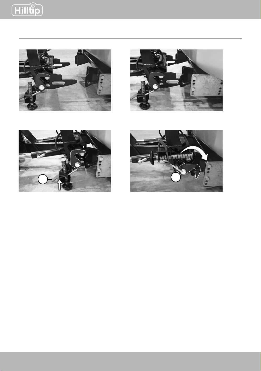
12
QUICK HITCH INSTRUCTIONS
Plow must be standing steady on the
ground, with plow shoes lowered
Align car and snowplow, slowly drive
car forward
Fit the plow horns in receiver push
beam, pull handle (1) up, the shoe
will lift off the ground
Pull and hold the lock pin out (2),
rotate handle up and release lock pin
12
34

SnowStriker
6 7
Down pressure function
Push the joystick knob upwards (lower
plow-position) for more than 3 seconds to
apply down pressure. This function presses
the snowplow down to the ground to give you
a cleaner scrape when plowing.
The downpressure-function will automatically
be deacitvated 30 seconds after it has been
applied.
*Automatic shut-down
The joystick/IO module and snowplow will
automatically shut down after being inactive for
5 minutes. To reactivate, move joystick knob or
turn it off and on again.
Lower plow
Angle rightAngle left
Lift plow
On/Off and
error indicator
Down pressure
indicator*
Scoop
position V-position
Windrow-right
position
Windrow-left
position
JOYSTICK
On/Off button

SnowStriker SnowStriker
8 9
ERROR CODES
Type/number
of ashes
Problem
Green light No errors detected
Constant red light Communication problem between IO box and joystick
1 ash Valve #1 or #2 not connected, or broken cable/coil
2 ashes Valve #3 or #4 not connected, or broken cable/coil
3 ashes Valve #5 or #6 not connected, or broken cable/coil
4 ashes Valve #7 or #8 not connected, or broken cable/coil
5 ashes Valve #9 or #10 not connected, or broken cable/coil
6 ashes Valve #11 or #12 not connected, or broken cable/coil
The on/off and error indicator LED located in the upper left corner of the joystick will show a green
light when turned on and if no errors are detected. If a problem is detected, the LED will ash with
a red light a number of times, pause, and then repeat.
SnowStriker
8 9
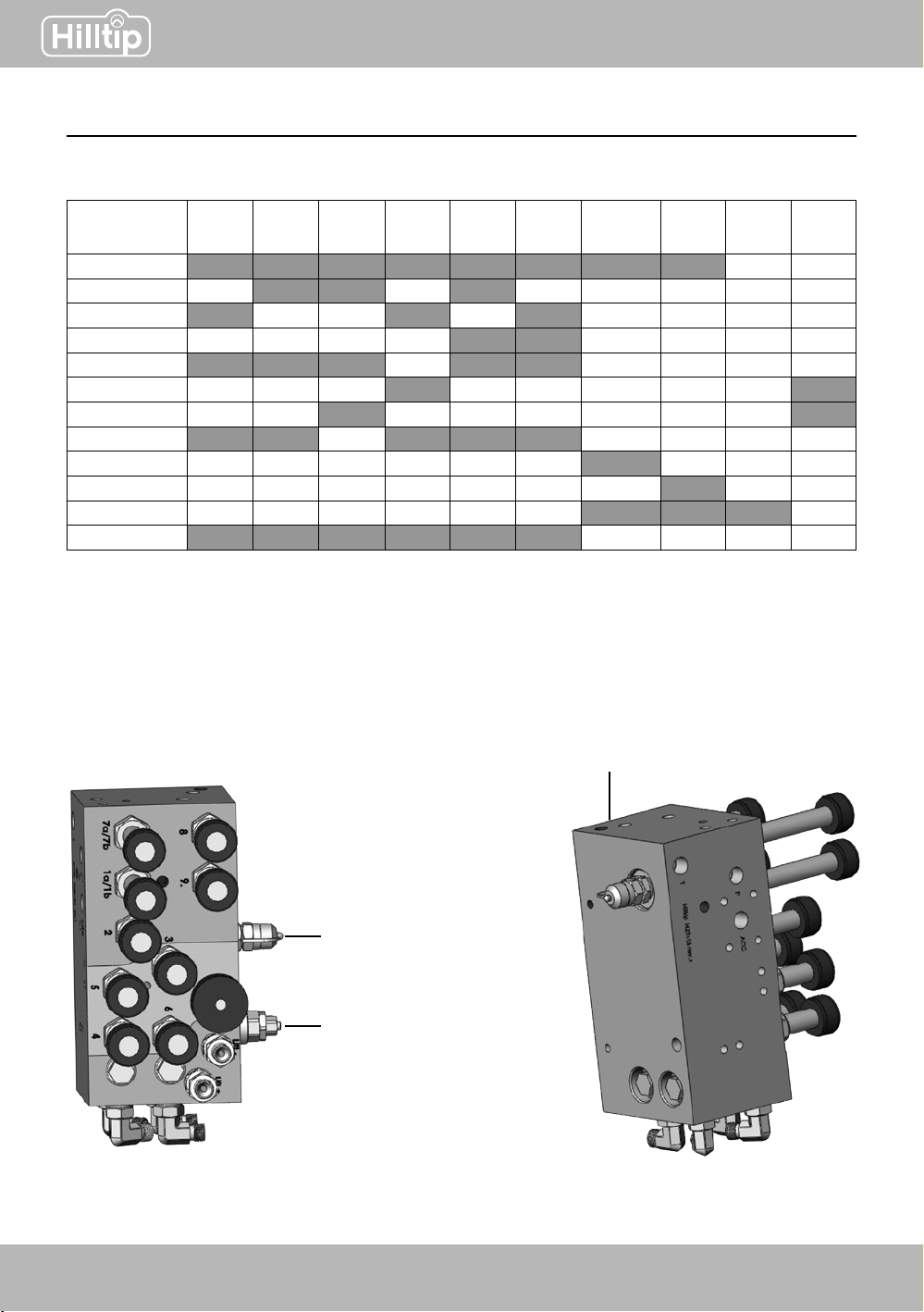
1
2 3
4
1. Main pressure
2. Adjust drop speed
3. Down pressure
gauge port
4. Down pressure
adjustment
Adjust cutting edge attack angle
PLOW DETAILS AND INSTALLATION INSTRUCTIONS
Wing-speed syncronizing valve
Grease ttings (x 3)
SnowStriker SnowStriker
10 11
4a.
b.
c.
2a.
b.
c.
d.
1
a.
b. c. d.
12
3
4
5
5
a.
b.
c.
d.
3
6
6a1
a2
b1
b2
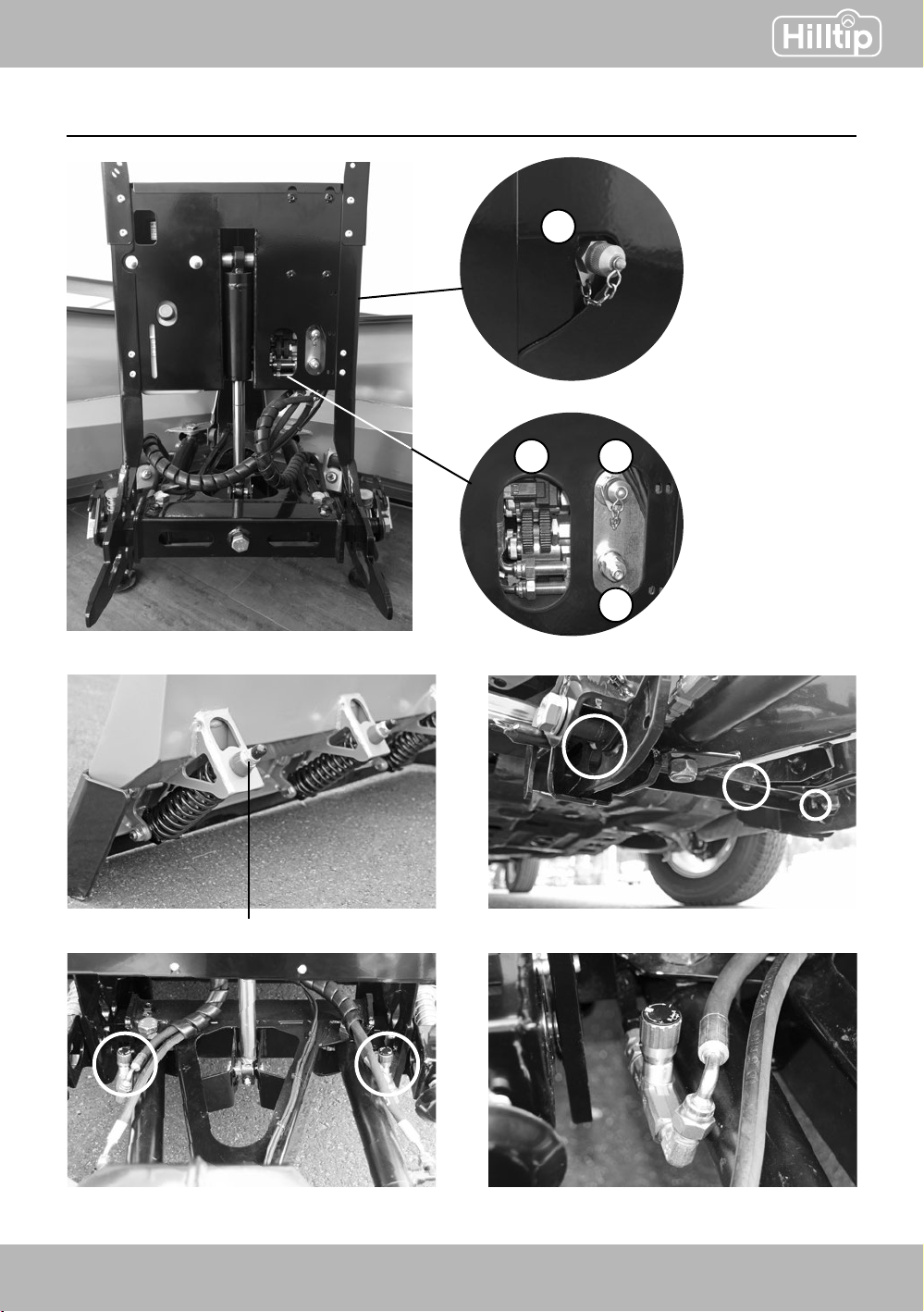
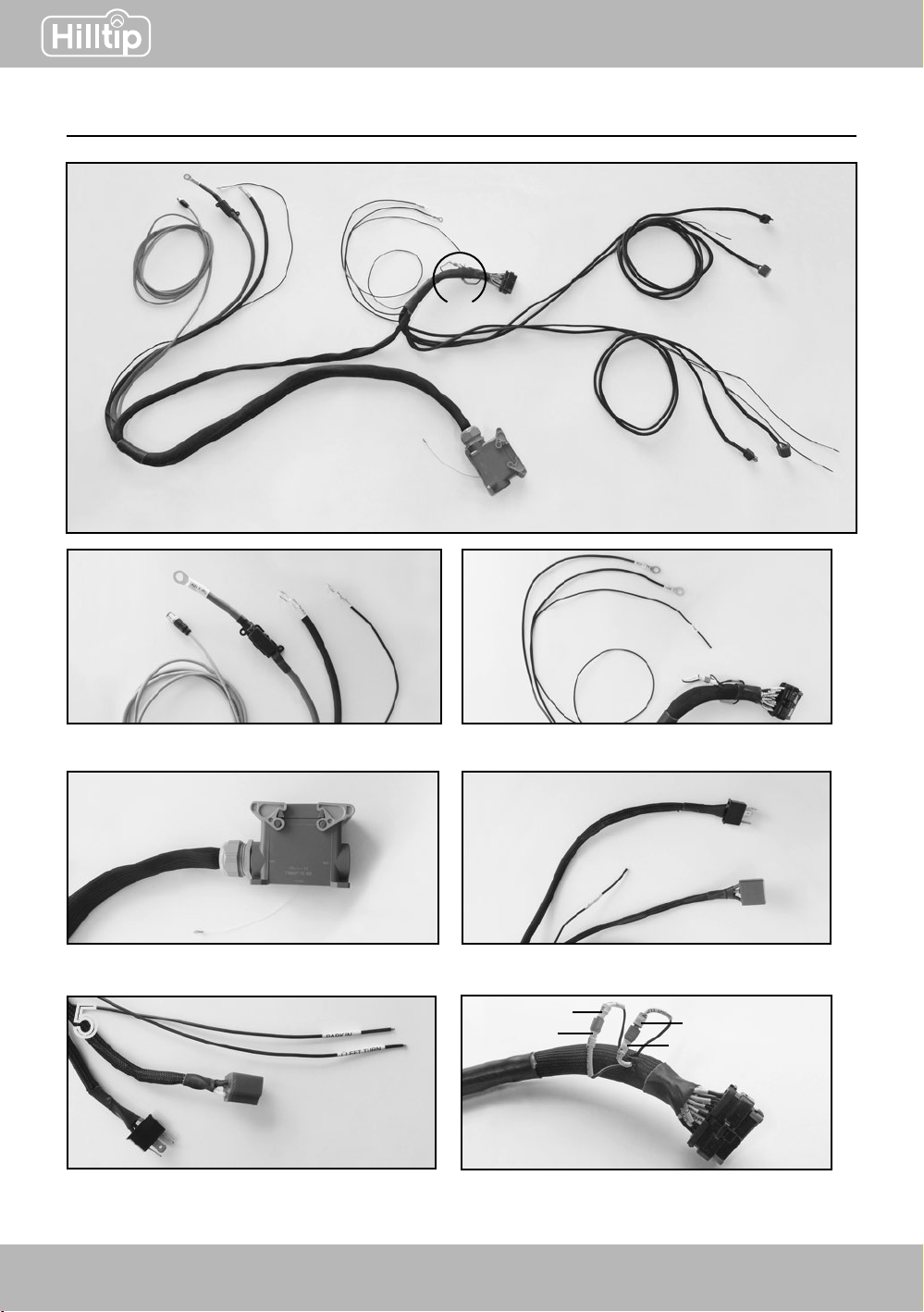
VEHICLE HARNESS
5a. Light connector (vehicle harness)
5b. Light connector (bulb)
5c. Left turn 5d. Park
4a. Light connector (vehicle harness)
4b. Vehicle light bulb 4c. Right turn
2a. Car +12V (VCC +12V) 2c. Switched power (IGN)
2b. Car ground (GND) 2d. Light module
1a. Joystick cable 1c. Car ground
1b. Car + 12V (red) 1d. Car ground (GND ATT IN)
Plow connector
Connect these harness cables according to pictures below:
6a1= 6a2= turn LEFT 6b1= 6b2= turn RIGHT
Switch these cables if the turn lights are ashing
on the opposite/wrong side

SnowStriker
10 11
PARTS
Blade assembly
Lift frame assembly
SnowStriker SnowStriker
12 13
Main pressure
PLOW VALVE ELECTRICAL FUNCTIONS
Pressure gauge port
Downpressure adjustment
0 - (max)50 bar
Factory setting: 30bar
Blade
movement
Angle
right
Angle
left
Right
extend
Left
extend Scoop Vee Down
pressure Raise Lower Idle
MOTOR
#1a
#1b
#2
#3
#4 1*
#5 1*
#6
#7a
#7b
#8
#9
1* = Goes low after 10 sec.

SnowStriker
12 13

SnowStriker SnowStriker
14 15
6d
10-12Nm
6e
25-28Nm
1
1a
2
2a
3
4
3a
3b
3c
5
5a
5b
5c
5d
6
6a
6b
6c
7-9Nm
7-9Nm
7-9Nm
25-28Nm
6f
25-28Nm
7
PARTS - HYDRAULIC POWER PACK

SnowStriker
14 15
Item Qty Part number Description
11H24515 Motor
1a 1H24516 Coupling
21H24517 Start Switch
2a 1H24518 Hose clamp
31H24519 Adapter block
3a 1H24520 Check valve
3b 1H24521 Plug
3c 1H24522 O-ring
41H24523 Relief valve
51H24524 Pump
5a 2H24525 Screw
5b 2H24526 Spring washer
5c 1H24527 Suction hose
5d 1H24528 Suction lter
61H24529 Tank
6a 1H24530 Hose clamp
6b 4H24531 Bolt
6c 4H24532 Spring washer
6d 4H24533 Triangle washer
6e 1H24534 Tank breather
6f 2H24535 Return hose
71H23942 Power unit “assembled”
PARTSLIST - HYDRAULIC POWER PACK

DECLARATION OF CONFORMITY
Manufacturer’s & Assambler’s Name: Oy Hilltip Ab
Manufacturer’s & Assambler’s Address: Pukkisaarentie 6, FIN-68600 Pietarsaari, Finland
Equipment Description: Hilltip Snowplow Applications
Equipment Model Designation: Hilltip SnowStriker 1850-VP, 2100-VP, 2250-VP
Equipment applications: Pickup/Truck
The equipments specied above are manufactured, where applicable, in conformity with provisions of
the normative document according to the following directives and standards, in addition to relevant
Road Trafc Regulations in European countries:
- 2006/42/EC
- EN 15432-1
- 2009/433/EG
I, the undersigned, hereby declare that the equipments specied above, that have been assambled by
Oy Hilltip Ab, conforms to the above directives and standards
Pietarsaari August 3rd, 2015 Signature:
Printed Name: Tom Mäenpää
Title: CEO
Installer’s Name:
Installer’s Address:
Type:
Serial number:
Year of installation:
I, the undersigned, hereby declare that the equipment installation to the vehicle specied above
conforms to the directive 2006/42/EC and relevant Road Trafc Regulations.
DATE: Signature:
Printed:
Title:

Oy HillTip Ab
Pukkisaarentie 6
68600 Pietarsaari
Finland
www.hilltip.com
+358 50 5983 026
+358 50 3659 415
This manual suits for next models
2
Table of contents
Popular Automobile Accessories manuals by other brands


BrandMotion
BrandMotion FLEETWORKS FLTW-7631 installation instructions

Herd
Herd PB11C4-02 installation guide

dirna Bergstrom
dirna Bergstrom Bycool Green Line Compact 3.0 Mounting instructions

InnotechRV
InnotechRV JET-M-400C operating instructions

Bosch
Bosch 1987 432 277 Installation instruction

Nav TV
Nav TV RGB-PCM3.1N manual


