Hilma 2174-160 User manual

02/2002 1
Operating instructions
Swing Clamp
Double acting Type 2174-160 / 2174-200
2175-160 / 2175-200
2176-160 / 2176-200
Special types
8.217x.8xxx
Carr Lane Roemheld Mfg. Co.
16345 Westwoods Business Park Drive
Ellisville, MO 63021
Phone: (800)-827-2526
Fax: (636)-386-8034
www.clrh.com

O p e r a t i n g i n s t r u c t i o n s
2
Please read the operating manual before installing the swing clamping cylinders and
putting them into operation for the first time!
1 Safety information
1.1 General
The safety of Hilma-Roemheld swing clamping cylinders has been thoroughly checked. They are designed for
use as specified in the technical data. If the technical data is not observed, there may be a danger to the
operator and proper functioning of the machine may be put at risk. Unauthorised modification or alteration of
Hilma-Römheld pull clamping cylinders is prohibited for reasons of safety. If this instruction is not observed, our
guarantee will be invalid.
1.2 Field of application
Hilma-Römhelld swing clamping elements are designed for a large number of clamping applications, in
connection with screw or tie rods or T-bolt supports. Swing clamping cylinders type 2170 are particularly suited
for the clamping of dies on presses when standardised dies with clamping slots or Hilma- clamping flanges are
used.
1.3 Operating characteristics
The load values specified for Hilma Römheld swing clamping cylinders must not be exceeded (see data sheets
in the appendix).
Attention: Overloading the swing clamping cylinders may lead to failure of the elements or to their
destruction.
1.4 Temperatures
The maximum operating temperature for the standard design is 70 °C. In case of higher temperatures special
designs with high-temperature sealing must be used (special designs for max. temperatures of 230°C without
proximity switches)
1.5 Important safety information
-Depending on the installation, there may be pinch hazard between the swing clamping element and the
clamping point
-Keep hands and tools away from the clamping range when operating the hollow piston cylinders.
Attention:
Before putting the swing clamping cylinders into operation, the operator must be fully trained.
Young people less than 16 years old are not allowed to operate the clamps. Staff aged over 16 years are
allowed to operate the clamps under supervision as part of their apprenticeship. The operating instructions must
be readily accessible. The operator must inform third parties of any danger in the working area.
1.6 Manufacturer's declaration
Hilma- Römheld swing clamping cylinders have been developed, designed and manufactured in accordance
with the EC Directive 'Machinery' ML89/392/EWG. The complete text of the manufacturer's declaration will be
made available on request.
O p e r a t i n g i n s t r u c t i o n s
3
2 Design and function
2.1 Design
The swing sink clamping elements consist of the housing, which accommodates the swing mechanism for the
piston, inductive proximity switches for monitoring the unclamping, and clamping position and the piston with
the tie rod.
The swing mechanism consists of a guide pin which guides the piston in such a manner that it rotates during
part of the stroke. The rotating movement is carried out just before reaching or after leaving the extended
position (unclamping position).
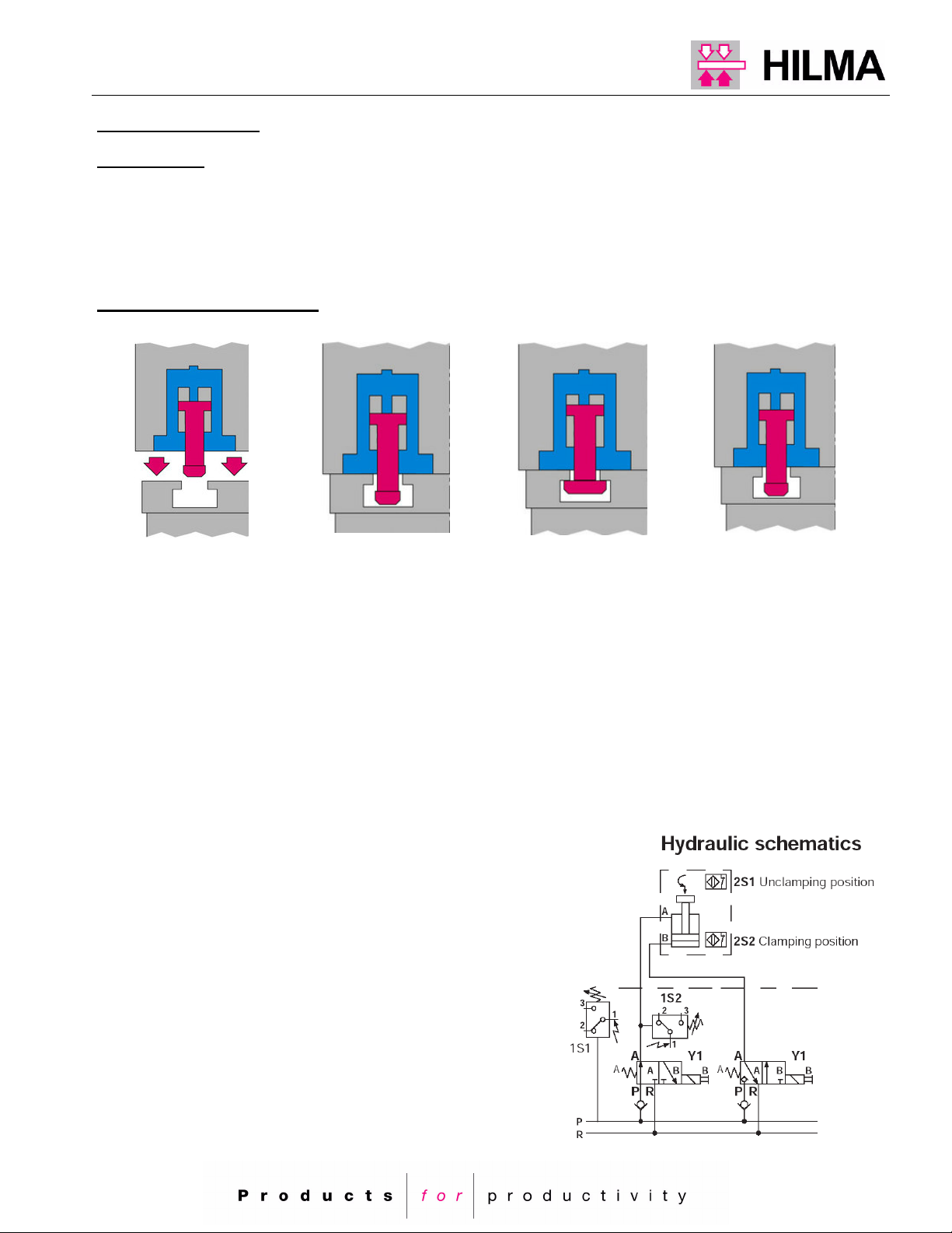
2.2 Functional description
1 2 3 4
Clamping
1. Push the die into the press with the swing clamping elements in the extended (unclamping) Position.
2. Lower the press ram onto the upper part of the die. The tie rods of the swing clamping elements will
pass through the clamping slots of the upper die.
3. The swing clamping elements are operated by means of a power unit. The tie rod rotates 90°and
is then in a transverse position to the clamping point. The upper die is hydraulically clamped. Once the
clamping pressure has been reached the power unit will be switched off by the pressure switch 1S2
Unclamping
4. Move the die together and return the swing clamping
elements into the unclamping position by means off
energising the valves Y1 and Y2.
The tie rod moves out and rotates 90°and can
pass trough the clamping slot of the upper die.
Move the press ram upwards and take the die out.
O p e r a t i n g i n s t r u c t i o n s
4
2.2.1 Monitoring of tie rod position
In order to ensure safe functioning of the swing clamping elements it is necessary to monitor the unclamping,
change-over and clamping position, so that signals for die change and machine operation are available and any
malfunction is indicated immediately. For this purpose, inductive proximity switches are integrated in the
cylinder housing. They react to switching positions of the piston rod. The signals for the clamping, change-over
and unclamping positions can also be displayed on the control panel, in order to facilitate trouble shooting in the
event of a failure. In the control system, the signals are required together with the signals emitted by the power
unit pressure switches in order to ensure a trouble free cycle of the swing sink clamping elements.
When using distribution block 5700-015, failures are indicated by LEDs and can be localized.
(For a description of the distribution block, see chapter 4.3 'Electrical installation'.
For functional dimensions for the tie rod position, see chapter 3.0 'Technical data, main dimensions'.)
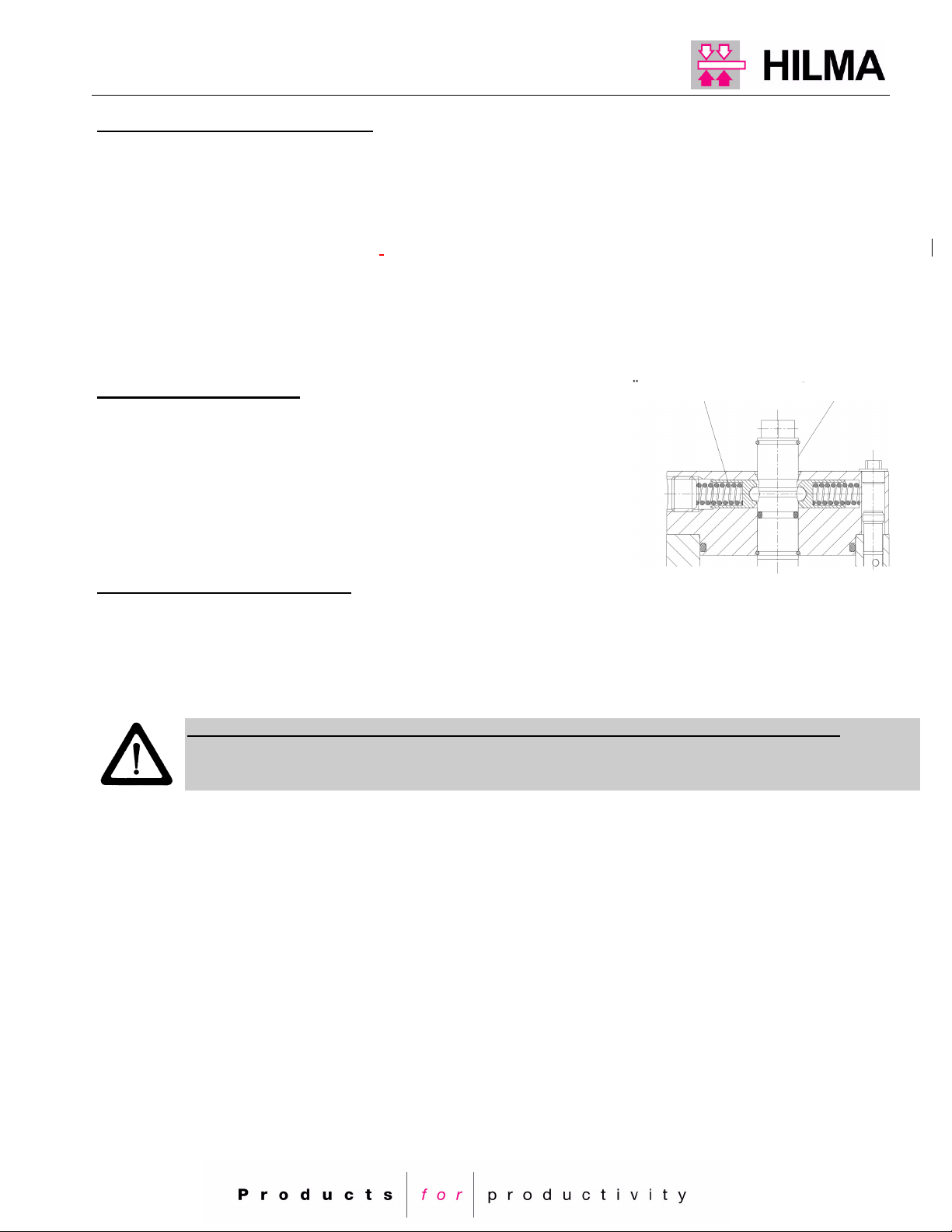
2.2.2 Overload protection
Free-swinging movement of the tie rod must be ensured.
If there is nevertheless an obstacle in the swinging range of the tie
rod, the swing mechanism is protected by overload protection. In
the case of a failure, the guide pin that is kept in position by spring-
loaded balls will disengage.
(For repositioning the guide pin, see chapter 2.2.3, emergency hand
control and chapter 5.0 'Trouble shooting')
2.2.3 Emergency manual control
When the overload protection has tripped or the swing sink clamping elements have fallen out of step, the guide
pin can be repositioned and the tie rods can be reset to allow uniform movement by manually rotating the guide
pin.
An external hexagon on the guide pin at the rear of the clamping element and an internal hexagon on the
clamping head of the tie rod provides for manual resetting.
Free access to one of the two hexagons for emergency manual control must be ensured!
Access may be achieved by a firmly installed extension to the external hexagon on the guide pin (e.g. by a
rod assembly with reversal of the direction or by a universal joint)
Only apply emergency manual control in a depressurized condition!
Overload protection guide pin

O p e r a t i n g i n s t r u c t i o n s
5
3. Technical data, main dimensions
Swing clamping element

O p e r a t i n g i n s t r u c t i o n s
6
4 Installation, connection and putting into operation
4.1 Storage and transport
During transportation, clamping elements must be protected against mechanical damage. For medium term
storage, they should be kept in a closed dry space. Even for short-time storage in the open air they should be
protected against harmful environmental influences.
4.2 Installation
- Installation work must only be carried out when the system is in an unpressurised condition.
- Prepare the bore pattern according to the drawing / data sheet in the catalog.
4.2.1 Hydraulic installation
Connect the swing clamping elements using DIN 2353 screw fittings (heavy design) (for connections, see
chapter 3 'Technical data, main dimensions').
The hydraulic tubing on the machine side must be of sufficient size (type 2174: 8x2 DIN 2391-St35 NBK or
larger; types 2175, 2176, : 12x2.5 DIN 2391-St35 NBK or larger) must be installed in accordance with the
specifications (DIN EN 982) and must conform to up-to-date practice for high-pressure hydraulics.
- Pipes should be as short as possible; pipe bends should have a large radius.
- Neat installation is essential for trouble-free operation of the system.
- Make sure that the pipe ends are free from burrs and that pipes, high-pressure hoses and screw fittings
are cleaned and blown through.
- Protective plugs should only be removed immediately before connecting the hydraulic system.
- Swing clamps that belong together should be connected to manifold blocks, series connection should
be avoided.
- Tubing leading to the power unit should be of sufficient diameter to avoid backpressure.
- Area ratio A : B = 1 : 1.,5 ; max. back pressure to connection B = 50 bar
- Provide each hydraulic port with a pressure gauge connection to enable check and adjustment of
operational data. This allows the locality of functional errors to be established quickly
- Pipes should be fastened using pipe clamps.
- When using hoses, keep the minimum bending radius
4.3 Electrical installation, plug assignment
Each swing clamp is provided with 2 proximity switches for monitoring the clamping, and un-clamping position.
Clear, easy-to-maintain installation is achieved when the connecting cables are connected to a distributor block
on the bed or on the ram. From here, the cables of all connected swing sink clamping elements are bundled and
connected to the control cubicle in the form of 16-wire cables.
O p e r a t i n g i n s t r u c t i o n s
7
4.4 Controls
4.4.1 Hydraulic and electrical controls
The swing clamping elements are controlled by a power unit which, for reasons of safety, is completely
separated from the hydraulic system of the machine.
As oil is only required for clamping and unclamping, the power unit operates intermittently. A pressure relief
valve protects the hydraulic systems against overpressure. When the operating pressure (max. 400 bar) is
reached, a pressure switch switches the motor off. If pressure drops 10% below the set value same pressure
switch causes the motor to start again.
The valves are of the seat valve type. The 24V solenoids are designed for 100% duty and deenergized when
the swing clamping elements are clamped. This ensures a long service life and furthermore, the clamping force
is maintained even in the event of power failure.
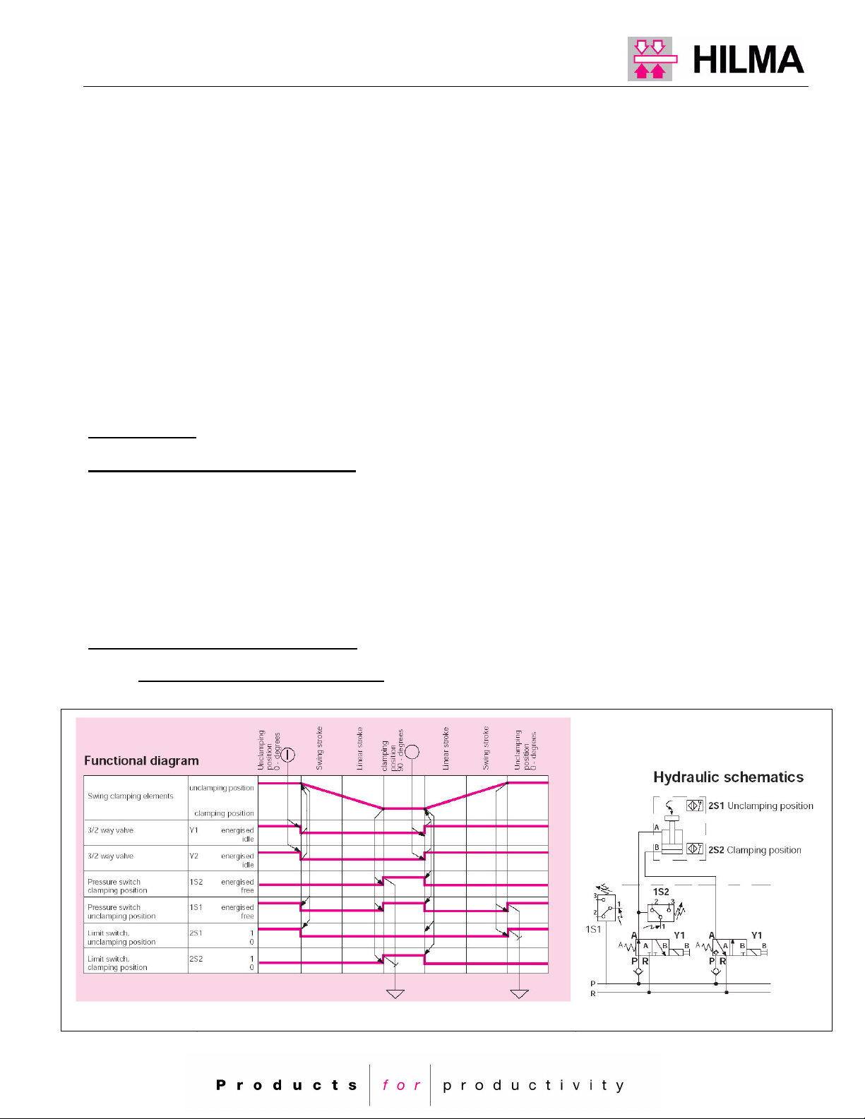
4.4.2 Hydraulic schematics, flow chart
Swing sink clamping element type 215x
4.4.3 Clamping and unclamping time
When changing dies, the time required for hydraulic clamping and unclamping is rather short. The capacity of
the power unit must be designed so that the clamping and unclamping cycle takes between 10 and 30 seconds.
Shorter cycles are not recommended for the reason of functional safety.

O p e r a t i n g i n s t r u c t i o n s
8
4.4.3 Safety levels
Although malfunctions seldom occur on hydraulic quick clamping systems, failure of a component cannot be
completely excluded.
In order to avoid the consequences of such a failure having an impact on the clamping safety, three safety
levels are provided, and at least two of them should be installed.
Clamping and unclamping cycle:
Qp = (V * z * 60) / (t * 1000) in sec
t = Clamping / unclamping cycle (s)
V = Oil consumption / swing sink clamp (cm3)
z = Number of swing sink clamps
Qp = Pump capacity (l/min)
4.4.4 Position monitoring, die and ram

O p e r a t i n g i n s t r u c t i o n s
9
In order to protect the dies and the swing clamping elements, the correct die position must be monitored by a
proximity switch.
Only once the die is correctly centred can clamping be carried out.
The ram, too, must be provided with a proximity switch which permits clamping after the ram is in contact with
the die surface.
4.5 Putting into operation
Read the operating manual before putting the system into operation!
When all hydraulic and electrical connections have been checked the system can be put into operation.
Make a test run with or without a die. If you make the test run without the die, the proximity switches will not
monitor the clamping position.
In the test run / manual operation the position monitoring of die and ram must be circumvented (selector
switch).
In the operating position of the selector switch (no test run) clamping and unclamping is initiated by a push-
button and will then take place automatically.
ATTENTION: When the die is clamped, the pump unit must not be switched off. This
also applies to week-ends. Exception: the die is closed, or the upper half of the die is
mechanically locked!
4.5.1 Filling with oil
Only use clean, new hydraulic oil HLP 32 DIN 51524, viscosity 150 VG 32 as per DIN 51519.
4.5.2 Starting and bleeding
Bleed the complete system with the pump running at low pressure (=20 bar, in the case of back pressure
possibly higher) at the highest point. In order to achieve this, slightly open a screw fitting until the oil emerging is
free from bubbles.
Operate all swing sink clamping elements several times until all movements are free from jerks and are
completed in the calculated time.
Check the hydraulic installation for tightness. Visually check all pressurized pipes, hoses, screw fittings and
clamping elements.
Check the oil level when the swing sink clamps are in an unclamped position. Refill with hydraulic oil, if
necessary.
ATTENTION: When clamping and unclamping operations are carried out, keep your
hands well away from the moving range of the swing sink elements.
DANGER OF INJURY!
4.5.3 Setting the operating pressure
− Set the pressure switch for pump control to the highest value.
− Switch on the pump.
− Set the operating pressure on the pressure relief valve approx. 10% above the desired operating
pressure.
− Reset the pressure switch for pump until the pump switches off. Switch the pump on and off several times,
thereby setting the pressure switch to the desired operating pressure.

O p e r a t i n g i n s t r u c t i o n s
10
ATTENTION: In order to prevent continuous running of the pump which might cause
damage, the pressure relief valve must be set to a value which is approx. 10% above
the tripping point of the pressure switch!
− Set the pressure switch for the machine controls approx. 15% below the operating pressure.
5 Trouble shooting
The swing sink clamping elements have left our premises in perfect condition. All functions have been tested, and
necessary adjustments have been made.
If any malfunction should occur even though the conditions stipulated in chapter 4.0 (Installation and putting into
operation) have been duly observed, please try to establish the cause using the table below.
ATTENTION: Only carry out repairs on the hydraulic system when no die is in the
machine, the system is switched off and all circuits have been depressurized by
manually operating the directional valves. Install the dies once all functions have
been tested and they perform impeccably!
Failure 1 The clamping pressure is not maintained. The pump is running frequently.
Cause Loose hydraulic fitting.
Remedial action Find leakage. Tighten the screw fitting in a depressurized condition.
Cause Loose, dirty directional valve. Leakage from P to R.
Remedial action Check in which circuit pressure falls. Dismantle the directional seat valve and clean or
replace it.
Cause Seals in the swing sink element, in the pressure switch or the directional seat valve are worn
out.
Remedial action Have seals replaced by qualified personnel or send clamping element for repair.
Cause Check valve in the valve block is loose.
Remedial action Flush the check valve. To do this, manually actuate the directional seat valve (clamping
circuit P) while the pump is switched on. If still loose, replace the check valve.
Failure 2 Tie rod position monitoring with permanent signal or without a signal.
ATTENTION: In the case of malfunction of the tie rod position check the function of the proximity switches using
an initiator testing device on the terminal box (see chapter 4.3 'Electrical installation'). Then check the
evaluation electronics.
Cause for a permanent signal Short circuit in the control line, proximity switch defective or switching
interval too long.
Cause for no signal Control line interrupted, proximity switch defective or guide pin disengaged.
Remedial action Check the electrical installation and the swing sink clamping element, have
it repaired by HILMA experts, if necessary
If the guide pin has disengaged, take a hexagon tool to turn it in the
correct position. (see chapter 2.2.2)

O p e r a t i n g i n s t r u c t i o n s
11
6. Maintenance and repair
Under normal conditions, hollow piston cylinders do not need special maintenance. However, a visual check of
the hollow piston cylinders and any hoses used should be carried out once a week.
In the case of frequent clamping cycles or in a dirty environment along with high temperatures, the
checking frequency should be increased.
Hydraulic valves are very sensitive to dirt. Make sure that no impurities get into the hydraulic fluid. We
recommend that the oil is changed once a year.
When carrying out routine maintenance work on the press:
- inspect the hydraulic system
- check the hydraulic system for tightness.
Note: The hydraulic system is designed to DIN EN 982 "Safety-related requirements on hydraulic systems and their
components".
For the list of spare parts and installation drawings, please refer to chapter 7 (Technical appendix) and note the
general information of the Hilma Catalog and the details of the swing clamping element data sheet.
After replacing a clamping element, move the new element several times in order to bleed the system through
the pump unit (the same applies if hydraulic connections have been disconnected).
For putting the system into operation, see chapter 4.0 (Installation, connection and putting into
operation).
7 Technical appendix, list of spare parts
When ordering spare parts, please indicate the type number engraved on the cylinder, the number and the
designation of the component, which are specified in the spare parts lists.
This manual suits for next models
5
Table of contents


