manuals.online logo
Brands
  1. Home
  2. •
  3. Brands
  4. •
  5. Siemens
  6. •
  7. Industrial Equipment
  8. •
  9. Siemens UP 117C12 User manual

Siemens UP 117C12 User manual

P.T.O.
Technical Manual
Bus Coupling Unit (BTM)
UP
117C12
5WG1117
–2CB12
April 2020
/ Page 1
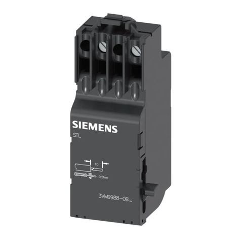
Product and Applications Description
Bus Coupling Units (BTM) provide the connection to the bus
for DELTA switches and wall box mounted control devices
with Bus Transceiver Interface (BTI).
The Bus Coupling Unit (BTM) comes with a mounting frame
for NEMA type wall boxes.
Application Program
The Bus Coupling Unit (BTM) does not require an application
program.
More information www.siemens.com/gamma-td
Example of Operation
KNX
Technical Specifications
Power supply
Input voltage
•Bus: DC 24 V (DC 21 ... 30 V)
Output voltage and current via BTI
•DC 5 V, 10 mA
•DC 20 V, 25 mA
Operator elements
The device has no operator elements.
Display elements
The device has no display elements.
Connections
•Bus line : screwless bus connection block (red-black)
0.6…0.8 mm Ø single core
•10-pin socket (BTI): for connection of DELTA switches
and wall box mounted control devices with BTI plug
Physical specifications
•housing: plastic
•dimensions (L x W x D): 110 x 64 x 18 mm
•weight: approx. 60 g
•installation: mounted with mounting frame on NEMA
type wall boxes
Electrical safety
•degree of pollution (according to IEC 60664-1): 2
•protection (according to EN 60529): IP 20
•overvoltage class (according to IEC 60664-1): III
•bus: safety extra low voltage SELV DC 24 V
•the device complies with EN 50428
Electromagnetic compatibility
complies with EN 50428, EN 61000-6-2 and EN 62479
Environmental specifications
•climatic conditions: EN 50090-2-2
•ambient temperature operating: - 5 ... + 45 °C
•ambient temperature non-op.: - 25 ... + 70 °C
•relative humidity (non-condensing): 5 % to 93 %
Markings
EIB, KNX
Listings and Certifications
CE mark
complies with the EMC regulations (residential and func-
tional buildings) and low voltage regulations
Electromagnetic compatibility
USA:
This device complies with part 15 of the FCC Rules. Opera-
tion is subject to the following two conditions:
(1) This device may not cause harmful interference, and
(2) this device must accept any interference received, in-
cluding interference that may cause undesired operation.
This equipment has been tested and found to comply with
the limits for a Class B digital device, pursuant to part 15 of
the FCC Rules. These limits are designed to provide reason-
able protection against harmful interference in a residential
installation. This equipment generates, uses and can radiate
radio frequency energy and, if not installed and used in ac-
cordance with the instructions, may cause harmful interfer-
ence to radio communications. However, there is no guar-
antee that interference will not occur in a particular installa-
tion. If this equipment does cause harmful interference to
radio or television reception, which can be determined by
turning the equipment off and on, the user is encouraged to
try to correct the interference by one or more of the follow-
ing measures:
- Reorient or relocate the receiving antenna.
- Increase the separation between the equipment and
receiver.
- Connect the equipment into an outlet on a circuit different
from that to which the receiver is connected.
- Consult the dealer or an experienced radio/TV technician
for help.
This device complies with Part 15 of the FCC rules.
Changes or modifications not expressly approved by Sie-
mens Schweiz AG could void the user’s authority to operate
the equipment.
United States representative:
https://new.siemens.com/us/en/products/buildingtechnologies/home.html
Canada:
CAN ICES-3(B)/NMB-3(B)
USA
L1V30044656A
RS-AC
Technical Manual
Bus Coupling Unit (BTM)
UP
117C12
5WG1117
–2CB12
April 2020
/ Page 2
Location and Function of the Display
and Control Elements
A1 Bus Transceiver Interface (BTI) socket for connecting an
application unit with BTI plug
A2 Slots for attaching the Bus Coupling Unit (BTM) to wall
boxes
A3 Slots for mounting application unit with guide and
mounting clamps
A4 Thread for mounting screws (for additional support,
e.g. for securing the application unit against theft)
A5 Type plate
A6 Bus connection block for single core conductors with
Ø 0.6 ... 0.8 mm
Dimension Diagram
Dimensions in mm
B1 NEMA wall box (minimum internal width: 50mm)
B2 Bus coupling unit (BTM)
B3 Bus Transceiver Interface (BTI)
B4 Mounting screw holes
B5 Mounting screws
B6 Design frame
B7 Wall switch
Mounting
General description
The connection to the bus line is established via bus connec-
tion block (screwless plug-in terminals for single core conduc-
tors). The application unit is slipped onto the bus coupling
unit (BTM) via guide and mounting clamps and, depending on
the device type, fastened with screws.
Note
The Bus Coupling Unit (BTM) must be mounted with the Bus
Transceiver Interface (BTI) situated at the bottom. Thus, the
application unit will be oriented properly when slid onto the
BTI. Use bus devices with mounting screws only to achieve a
permanently stable contact at the BTI.
C2.2 C2.1
C2.3
C2
D1
D2
5 mm
D1
D2
Wiring
Slipping off/on bus connection blocks
The bus connection block (C2) is situated on the back of the
bus coupling unit (BTM) (C1).
It consists of two components (C2.1 and C2.2) with four ter-
minal contacts each. Take care not to damage the two test
sockets (C2.3) by accidentally connecting them to the bus ca-
ble or with the screw driver (e.g. when attempting to unplug
the bus connection block).
Slipping off bus connection blocks
- Carefully put the screw driver to the wire insertion slit of
the bus connection block’s grey component (C2.2) and
- pull the bus connection block (C2) from the bus coupling
unit (BTM) (C1).
Note
Don’t try to remove the bus connection block fromthe bottom
side. There is a risk of shorting-out the device!
Slipping on bus connection blocks
- Slip the bus connection block (C2) onto the guide slot of
the BTM (C1) and
-press the bus connection block (C2) down to the stop.
Connecting and Disconnecting bus cables
Connecting bus cables
-The bus connection block (D1) can be used with single
core conductors Ø 0.6…0.8 mm.
- Remove approx. 5 mm of insulation from the conductor
(D2) and plug it into the bus connection block (D1)
(red = +, black = -)
Disconnecting bus cables
- Unplug the bus connection block (D1) and remove the
bus cable conductor (D2) while simultaneously wiggling
it.
USA
C2
C1
A2
A5
A1
A2
A4
A4
A3
A6
B1
B2
B3
B4
B5
B6
B7
Class 2 power wiring only.
WARNING
The device must be mounted and commissioned by an authorized electrician.
The device must not be opened.
A device suspected faulty should be returned to the local Siemens sales office or distributor.
The prevailing safety rules must be heeded.

Other Siemens Industrial Equipment manuals

Siemens BD2 User manual

Siemens

Siemens BD2 User manual

Siemens SIMATIC NET RUGGEDCOM RX1511 User manual

Siemens

Siemens SIMATIC NET RUGGEDCOM RX1511 User manual

Siemens SIMATIC NET RUGGEDCOM RX5000 Technical Document

Siemens

Siemens SIMATIC NET RUGGEDCOM RX5000 Technical Document

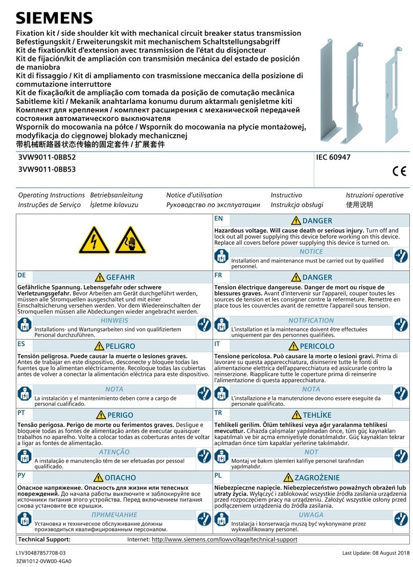
Siemens 3VW9011-0BB52 User manual

Siemens

Siemens 3VW9011-0BB52 User manual

Siemens 5WG1 425-7AB72 Service manual

Siemens

Siemens 5WG1 425-7AB72 Service manual

Siemens 7SR157 Argus User manual

Siemens

Siemens 7SR157 Argus User manual

Siemens SIRIUS 3RT101-2-0LA Series User manual

Siemens

Siemens SIRIUS 3RT101-2-0LA Series User manual

Siemens SIVACON 8PS BD2 Series User manual

Siemens

Siemens SIVACON 8PS BD2 Series User manual

Siemens REDUREX User manual

Siemens

Siemens REDUREX User manual

Siemens 3NJ-1-3B 01 Series User manual

Siemens

Siemens 3NJ-1-3B 01 Series User manual

Siemens SIRIUS MCU 3RK4 32 Series User manual

Siemens

Siemens SIRIUS MCU 3RK4 32 Series User manual

Siemens SINUMERIK 840Di sl Owner's manual

Siemens

Siemens SINUMERIK 840Di sl Owner's manual

Siemens 3VA9680-0LF20 User manual

Siemens

Siemens 3VA9680-0LF20 User manual

Siemens 3RW3926-8A User manual

Siemens

Siemens 3RW3926-8A User manual

Siemens SIMATIC S7-200 User manual

Siemens

Siemens SIMATIC S7-200 User manual

Siemens SIMATIC TP700 Comfort Outdoor User manual

Siemens

Siemens SIMATIC TP700 Comfort Outdoor User manual

Siemens SITRANS SCM IQ User manual

Siemens

Siemens SITRANS SCM IQ User manual

Siemens 3VT9500-4EF30 User manual

Siemens

Siemens 3VT9500-4EF30 User manual

Siemens SIMATIC RF650R Instruction sheet

Siemens

Siemens SIMATIC RF650R Instruction sheet

Siemens LITHOSTAR Multiline SP Installation manual

Siemens

Siemens LITHOSTAR Multiline SP Installation manual

Siemens 3NW7613-4 User manual

Siemens

Siemens 3NW7613-4 User manual

Siemens SIVACON 8PS BD01 User manual

Siemens

Siemens SIVACON 8PS BD01 User manual

Siemens PolyBlend PB200-2 User manual

Siemens

Siemens PolyBlend PB200-2 User manual

Siemens Sentron 5ST3 COM User manual

Siemens

Siemens Sentron 5ST3 COM User manual

Popular Industrial Equipment manuals by other brands

TAJIMA TMEZ-SC user manual

TAJIMA

TAJIMA TMEZ-SC user manual

Endress+Hauser Micropilot FMR50 Safety instruction

Endress+Hauser

Endress+Hauser Micropilot FMR50 Safety instruction

PI NEXACT Stage N-565 Series user manual

PI

PI NEXACT Stage N-565 Series user manual

ABB AMG 0180 user manual

ABB

ABB AMG 0180 user manual

ZWAE OW Installation and service manual

ZWAE

ZWAE OW Installation and service manual

Numatics 450 Series Installation and maintenance instructions

Numatics

Numatics 450 Series Installation and maintenance instructions

probst SVZ-ECO-L operating instructions

probst

probst SVZ-ECO-L operating instructions

EUTHANEX SmartBox M1TSFF2C-FM manual

EUTHANEX

EUTHANEX SmartBox M1TSFF2C-FM manual

Carman SPEEDCHECK-15/18 quick start guide

Carman

Carman SPEEDCHECK-15/18 quick start guide

CHART ChillZilla VS-9000CZ product manual

CHART

CHART ChillZilla VS-9000CZ product manual

Mannesmann Demag FRV 100 installation instructions

Mannesmann Demag

Mannesmann Demag FRV 100 installation instructions

Ecosoft MO11XLWE instruction manual

Ecosoft

Ecosoft MO11XLWE instruction manual

Blacoh Sentry Installation & operation manual

Blacoh

Blacoh Sentry Installation & operation manual

Wavetronix Click 500 Series user guide

Wavetronix

Wavetronix Click 500 Series user guide

Machine Support Vibracon SM12CS manual

Machine Support

Machine Support Vibracon SM12CS manual

NARGESA MX340G Instruction book

NARGESA

NARGESA MX340G Instruction book

Ingersoll-Rand SSR UP5 11 Option manual

Ingersoll-Rand

Ingersoll-Rand SSR UP5 11 Option manual

Rayleigh Instruments RI-D340 instruction manual

Rayleigh Instruments

Rayleigh Instruments RI-D340 instruction manual

manuals.online logo
manuals.online logoBrands
  • About & Mission
  • Contact us
  • Privacy Policy
  • Terms and Conditions

Copyright 2025 Manuals.Online. All Rights Reserved.