Essemtec Fox User manual
Fehler! Unbekannter
Name für Dokument-
Eigenschaft.
Fox
Maintenance Manual
ObjectNo.
0000074/05
Release Date
March 31, 2017

Copyright
© Essemtec AG, Switzerland, 2017
All rights reserved. No partof this publication may be reproduced, stored, in a retrieval system, or
transmitted, inany means, electronic, mechanical, photocopying, recordingor otherwise, without the prior
written permission of the publisher.
The Fox works as is. Screenshots and description cover the actualbehavior as far as possible. The contentof
this manualdoes notgive any claim to software performance orimplemented software features.
Essemtec AG Customer Support
Headquarter
Essemtec AG
Mosenstrasse 20
CH-6287 Aesch/LU
Schweiz
Phone:
+41 41 919 60 60
Fax:
+41 41 919 60 50
Poland
Essemtec Poland
Wrzeciono 16/24
01-961 Warszawa
Germany
Essemtec Deutschland AG+Co.KG
Söckingerstrasse 12
82319 Starnberg
Tel:
+48 / 661 922 962
Phone:
+49 / 8151 2685501
Fax:
+49 / 8151 2685503
Mail: sales-poland@essemtec.com
North America & Mexico
Essemtec USA
816N. Delsea Drive #308
08028-1499 Glasboro, NJ
Phone:
+1 / 856 218 1131
Fax:
+1 / 856 218 1134
Mail: sales@essemtec-usa.com
Imprint
Fox Maintenance Manual
Concept: ArminMueller
Authoring: ArminMueller
Checked: Stefan Baumann
Approved: Fernando Marcos
OriginalLanguage: English
ManualFeedback: a[email protected]m
Essemtec Information: www.essemtec.com

Fox Maintenance © Essemtec AG iii
0000074/05 / March 31, 2017
Contents
1Materialsand Tool-Kits 1-1
1.1 MaterialsandTool-Kits Overview..............................................................................................................................1-1
2Configuration of the Machine 2-1
2.1 Configurationof Machine and Modules.................................................................................................................2-1
2.1.1 Introduction......................................................................................................................................................................2-1
2.1.2 ToolsandMaterial...........................................................................................................................................................2-1
2.1.3 Configuration Tasks........................................................................................................................................................2-2
3Calibration of the Machine 3-1
3.1 Introduction......................................................................................................................................................................3-1
3.2 Preparation/ Terminationfor XY Mapping............................................................................................................3-4
3.2.1 Machine with PCB Table(no conveyor)...................................................................................................................3-4
3.2.2 Machine with Conveyor................................................................................................................................................3-9
3.3 MechanicalAdjustmentPossibilities.....................................................................................................................3-11
3.3.1 PCB Handling.................................................................................................................................................................3-11
3.3.2 Cameras...........................................................................................................................................................................3-14
4Preventive Maintenance 4-1
4.1 Introduction......................................................................................................................................................................4-1
4.2 Preventive Maintenance Schedule...........................................................................................................................4-3
4.3 Daily Maintenance a.......................................................................................................................................................4-5
4.3.1 Tools, Material and Scheduling..................................................................................................................................4-5
4.3.2 Prerequisites......................................................................................................................................................................4-5
4.3.3 Used Tape cutting andremoving..............................................................................................................................4-6
4.3.4 RejectBin Emptying.......................................................................................................................................................4-7
4.3.5 ContaminatedAreas Cleaning(Dispensing).........................................................................................................4-7
4.3.6 Dispensing Valve Cleaning..........................................................................................................................................4-9
4.4 Weekly Maintenance a...............................................................................................................................................4-10
4.4.1 Tools, Material and Scheduling...............................................................................................................................4-10
4.4.2 Prerequisites...................................................................................................................................................................4-11
4.4.3 Safety Check...................................................................................................................................................................4-12

Contents
iv © Essemtec AG Fox Maintenance
0000074/05 / March 31, 2017
4.4.4 Bottom Vision GlassCleaning...................................................................................................................................4-14
4.4.5 Cover and Monitor Cleaning.....................................................................................................................................4-14
4.4.6 NozzleCleaning.............................................................................................................................................................4-15
4.4.7 Conveyor BeltChecking and Cleaning..................................................................................................................4-18
4.5 Weekly Maintenance b................................................................................................................................................4-19
4.5.1 Tools, Material and Scheduling................................................................................................................................4-19
4.5.2 Prerequisites...................................................................................................................................................................4-20
4.5.3 Feeder and Rack Cleaning..........................................................................................................................................4-20
4.5.4 Trailing Cable Checkingand Cleaning ..................................................................................................................4-21
4.5.5 Production AreaCleaning..........................................................................................................................................4-22
4.5.6 Linear Motor MagnetsChecking and Cleaning..................................................................................................4-23
4.6 MonthlyMaintenancea..............................................................................................................................................4-25
4.6.1 Tools, Material and Scheduling................................................................................................................................4-25
4.6.2 Prerequisites...................................................................................................................................................................4-26
4.6.3 Height Laser Cleaning.................................................................................................................................................4-27
4.6.4 Air Maintenance Unit Checking...............................................................................................................................4-27
4.6.5 Optical Measuring System Checking possibly Cleaning.................................................................................4-28
4.6.6 P&PHeadChecking......................................................................................................................................................4-29
4.6.7 Dispense Axes Cleaning/ Lubricating...................................................................................................................4-36
4.6.8 ConveyorClamping Checking/ Lubricating.......................................................................................................4-39
4.7 Yearly Maintenance c...................................................................................................................................................4-41
4.7.1 Tools, Material and Scheduling................................................................................................................................4-41
4.7.2 Prerequisites...................................................................................................................................................................4-45
4.7.3 Linear Slider / Rails Cleaningand Lubricating....................................................................................................4-46
4.7.4 Electronic Cabinets Checking and Cleaning.......................................................................................................4-48
4.7.5 Head Maintaining..........................................................................................................................................................4-50
4.7.6 Dispense Axes Linear Guide Cleaning / Lubricating........................................................................................4-58
4.8 Yearly Maintenance a..................................................................................................................................................4-59
4.8.1 Tools, Material and Scheduling................................................................................................................................4-59
4.8.2 Prerequisites...................................................................................................................................................................4-60
4.8.3 Machine Calibration.....................................................................................................................................................4-61
4.9 Stepsto gain Prerequisitsfor Maintenance.........................................................................................................4-62
4.9.1 GainingPrerequisitsa..................................................................................................................................................4-62
4.9.2 GainingPrerequisitsb.................................................................................................................................................4-63

Contents
Fox Maintenance © Essemtec AG v
0000074/05 / March 31, 2017
4.9.3 GainingPrerequisitsc.................................................................................................................................................4-66
5Corrective Maintenance 5-1
5.1 Introduction......................................................................................................................................................................5-1
5.2 MalfunctionTable...........................................................................................................................................................5-3
5.3 Preparation........................................................................................................................................................................5-3
5.4 P&PHead............................................................................................................................................................................5-5
5.4.1 Head V5 Vacuum Feedthrough Cleaning / Lubricating....................................................................................5-5
5.4.2 Head Removal fromMachine...................................................................................................................................5-15
5.4.3 Head Mounting ontoMachine................................................................................................................................5-19


Fox Maintenance © Essemtec AG vii
0000074/05 / March 31, 2017
About this Manual
History
Index
Release
Changes
01
September 15,
2016
Firstrelease
02
January 06,
2017
Procedure to rinse the vacuum passage extendedin chapter 'Head
Maintaining' ofYearly Maintenance c (spindle tip cleaning by meansof
the conical brush).
03
February01,
2017
Procedure forConveyor Clamping Checking/ Lubricating addedto
chapter 'MonthlyMaintenance a'.
Corrective Maintenance, chapter 'P&P Head', description if head removalis
required or not, has been improved.
Sub-chapter 'Head Removal from Machine', moved to theend of chapter
'P&P Head' to avoid anymisunderstandings.
04
February10,
2017
Corrective Maintenance, chapter 'MalfunctionTable', has beenimproved.
05
March 31,
2017
Part numberof grease added at all positions whereP&P Head Greaseis
used.
Procedure to rinse vacuum passage reworked.
Loctite 7063 replaced by IPA Isopropyl alcohol.
Purpose
ThisMaintenanceManualcontainsessential information(whereapplicable)concerning:
•the safe andefficient performanceof preventive maintenance tasks on the Fox
•the safe andefficient performanceof corrective maintenance tasks on the Fox
•the safe andefficient configuration and calibration ofthe Fox
•the schematics (electrical,electronic and pneumatic) of theFox
•the tool kitsused for calibration etc.
The knowledgeof and adherence to the safetyregulations andthe compliancewith additional
warning instructions described inthis Maintenance Manualis a basic precondition for a safe and
error free work with orat the Fox.
This document (Maintenance Manual) and especially the safety regulations have to be observed by
all personswho work with or atthe Fox. Additionally,all local safetyand environmental regulations
have to be observed.

AboutthisManual
viii © Essemtec AG Fox Maintenance
0000074/05 / March 31, 2017
How to Use
In general, this Maintenance Manualshould be usedin conjunction with allother relevant
documentation providedwith themachine. To findspecific informationquickly, alluser
informationcontain followingfeatures:
•Tableofcontents
•Cross-referenceswithin text
•Margin notes, pictograms, symbols etc.
•Glossary, givinga helpful list of themost frequentlyused terms ofSMT technology
Manual used as Reference Book
This MaintenanceManual can be used as reference book forworking with theequipment. All
equipment users can follow the task description stepseasy and fast. suggests to acquire
application knowledgein training courses.
Manual used as Training Information
This MaintenanceManual is structured according to the method of Performance Based Equipment
Training (PBET).Therefore it can be usedas training informationto pursue tasks stepby step. It will
be used in training courses.
AboutthisManual
Fox Maintenance © Essemtec AG ix
0000074/05 / March 31, 2017
Personnel Requirements
The maintenancetasks on the Fox, its modules or options may only be performed by authorized
maintenance personnel whofulfill the followingrequirements.
Function
Responsible for regularchecks of themachine, for cleaning and lubrication, forregular adjustments
as well as forremoval and replacementof faulty assemblies.
Duties and Responsibilities
•Handles materialand chemicals in a correct and safemanner.
•Knows how tointerpret material safety data sheets (MSDS).
•Interprets the maintenance information correctly.
•Interpretshints and errors and takes correctaction.
•Follows approved technical methods for maintainingthe Fox, modulesor optionsof it.
•Participates inregular trainings to maintain therequired levelof knowledge related to
maintain and service the equipment and trains subordinate personnel as required.
•Wears and uses protectiveequipment (goggles, protective gloves, etc.)when working with
aggressive substances.
CompulsoryReading
The Startup& Safety Manual is an integral partof the MaintenanceManual. Read the
Safety Chapter of the Startup & Safety Manual before working withor at the Fox.
Essemtec AG declines all responsibility for personal injuries or materialdamages
occurring as aresult of non-observance of the safety chapter's instructions an warnings.
AboutthisManual
x© Essemtec AG Fox Maintenance
0000074/05 / March 31, 2017
Signal Words and their Meanings
Throughout thisdocument, attention is drawn to safetyissues using thefollowing signal words:
Danger
Indicates an imminently hazardous situation which, if not avoided, will result in death or
serious injury. Thissignal word is limited to the mostextreme situations.
Warning
Indicates a potentially hazardous situation which, if notavoided, could result in death or
serious injury.
Caution
Indicates asituation which, if notavoided, may result in minor or moderate injury. It may
also be used to alert against unsafe practices.
Notice
Indicates a situation which, if notavoided, may result in equipment or material damage.
Safety Alert Symbol
Refers to a safety relevant text in the Startup & SafetyManual.

AboutthisManual
Fox Maintenance © Essemtec AG xi
0000074/05 / March 31, 2017
Pictograms and their Meanings
Pictograms areused in thisManual in order to supportthe understanding ofthe text and to
increase the efficiency ofthe practical work. Inline with textno pictograms areused.
Menu
-menu is written
next to the pictogram ina hierarchical form.
Example:
System
Calibration
XY gantry
Soft Key
Meaning of pictogram: "click the soft key ...". The corresponding soft keyis written next to the
pictogram in bold italic font.
Example:
Calibrateall
Tool
Meaning of pictogram: a tool is required to carry out a step in a procedure. Thepictogram is placed
next to the correspondinginstruction.
Example:
Tighten the fixation screw.
Check
Meaning of pictogram: aselection has to be done (check boxes). The pictogram is placed next to
the correspondinginstruction.
Example:
Setupcheck
Hint / Notification
Meaning of pictogram: apop up window giving a hint or awarning. The textof the pop upwindow
is written next to the pictogram in a non proportional font.
Example:
Make sure that all boards are removed before continuing calibration

AboutthisManual
xii © Essemtec AG Fox Maintenance
0000074/05 / March 31, 2017
Text Box
Meaning of pictogram: avalue (alphanumeric)has to be enteredby means of the on-screen
keyboard, after clicking the text box (usually a parameter). The pictogram is placed next to the
correspondingparametername.
Example:
Barcode, enter thebarcode of thefeeder.
Drop Down List
Meaning of pictogram:one of the presented itemson the drop downlist has to be selected, after
clicking the box (usually aparameter). The pictogram is placed next to thecorresponding
parameter name.
Example:
No of pick retries,select the desired numberof pick retries.

AboutthisManual
Fox Maintenance © Essemtec AG xiii
0000074/05 / March 31, 2017
Text Conventions and their Meanings
Various text styles are used in this Maintenance Manual in order to support the readabilityof the
text or to emphasizethe meaningof text segments.
Meaning
Description / Text Style
Example
Parameters and
actual Values
Machine parameters and actual values are
visualized by bold characters and in the same
spelling as inthe menu. Also the state of the
parameter iswritten in thesame way.
Set the parameter
Optimizationmode to
Maximum performance
Pickup 5 [ms]
Soft Key
Context sensitivefunction keys are written in
italic and bold. Normallythey are shown
together with the respective pictogram.
Press New to create a new
lightprofile
MenuKey
(Screen)
Startsa submenu. Same style asthe Soft Keys.
ProductionSettings
Check Boxes
Are located anywhere on ascreen. They have
same style as Soft Keys.
SelectSetupcheck
MenuTree
In a text flow thehierarchy of a menu is visu-
alized by using hyphensand bold characters.
Setup - Optimization -
Recipe Splitting
Screen
Screens are written in bold usingcapital and
smallletters.
... on Produce screen
Cross
Reference
Written in blue italic.
seeonpage...
Notification
Error
Warning
Appearing in a pop up window providing tips,
instructions and messages. They are writtenin a
non proportional font.
The following warning
appears:
No components found
to be produced
Note
If a certain subject must be emphasizedit is
written as anote.
Note:
Adjust the guide pins
symmetrically

AboutthisManual
xiv © Essemtec AG Fox Maintenance
0000074/05 / March 31, 2017
Information Concept
The User Documentation of theFox consistsof the following manuals andonline help:
•UnpackingInstruction
•InstallationManual
•Startup & Safety Manual
•Maintenance Manual
•ElectronicSparepartCatalogue
•OnlineHelp:
–Context Info with QuickHelp and How to information
–InfoPage
Fox Maintenance © Essemtec AG 1-1
0000074/05 / March 31, 2017
1 Materials andTool-Kits
1.1 Materials and Tool-Kits Overview
The materials and tool-kits describedin this chapter are necessary for:
•Configuration
•Calibration
•Preventive Maintenance
•CorrectiveMaintenance
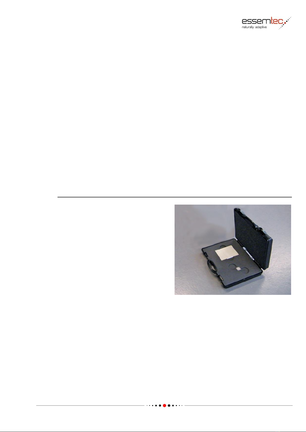
CAL-SET12 Tool-Kit for P&P Head Maintenance
Partnumber:CAL-SET12
The purposeof this set is to recalibrate the Pick
& Place Head.The kit consistsof:
•Glass plate 65 x 50 mm
•Aluminum calibration plate 15 x 15mm
MaterialsandTool-Kits
1-2 © Essemtec AG Fox Maintenance
0000074/05 / March 31, 2017
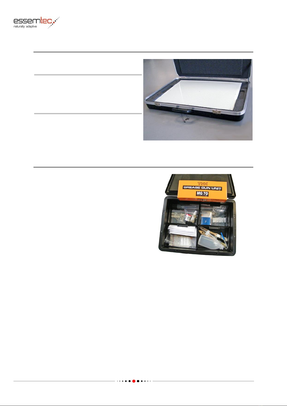
CAL-SET13 Tool-Kit for XY Mapping / Head Rotation
Partnumber:CAL-SET13
Note:
The CAL-SET13 Tool-Kit is not scopeof
the machine delivery.
The arrangement of thetools in the
delivered tool-kit may vary fromthe
illustration.
The purposeof this set is to calibrate the XY
mapping and head rotation. The kitconsists of:
•1x glass plate 300 x 610 mm
•4x supportpins PC-SUP-C00
SP26/MAIN05 Tool-Kit for P&P Maintenance Tasks
Partnumber:SP26/MAIN05
The purposeof this set is to provide thecorrect
toolsandmaterialsformachine maintenance.
The kit consists of:
•grease gun with greasefittings
•grease for linear carriages
•contact pins forPC feeder
•variousbrushesfor cleaning
•2x head assembly tool fordownholding the
ZT elements
•leaf springs for pulling back the nozzle on
the ZT element shaft
•microfibre eyeglass cloth for cleaning the
opticalmeasuringsystem
•squeeze bottle for rinsing the vacuum
passage
•various filters for valves
•vacuum silicon tubesfor head
•grease for head lubricating

MaterialsandTool-Kits
Fox Maintenance © Essemtec AG 1-3
0000074/05 / March 31, 2017
SP26/HG10 Grease Gun Kit
Partnumber:SP26/HG10
Note:
The Grease Gun Kit is not scope of the
machinedelivery.
The purposeof this kit isto provide thecorrect
grease gun for machinemaintenance either if
the original maintenance kit does not contain a
gun or to replacean old gun whichis worn out.
The kit consists of:
•1x gun complete
•1x grease cartridge
•1x grease gun adapter (bended spout)
•3x coupler for the different lubricating
nipples
Circlip Pliers
Partnumber:SP/TOOL-26
Note:
The circlip pliersis not scope of the
machinedelivery.
The delivered circlip pliers may vary from
the illustration.
The purposeof this tool isto maintain the P&P
head (vacuumfeedthrough cleaning and
lubricating)

MaterialsandTool-Kits
1-4 © Essemtec AG Fox Maintenance
0000074/05 / March 31, 2017
Pusher Needles
Partnumber:SP26/BN01-Tool
Note:
The pusherneedle kit is not scope of the
machinedelivery.
The arrangement of theneedles in the
delivered kitmay vary from the
illustration.
The purposeof this setis to pushout the
nozzles. The kit consists of:
•5 pusher needlesfor nozzle 1

Fox Maintenance © Essemtec AG 2-1
0000074/05 / March 31, 2017
2 Configurationof the Machine
For better visibility of subjacent functions, covershave been removed or opened before
taking pictures. In standard operating mode all covers have to be in place at any time.
2.1 Configuration of Machine and Modules
Since the configuration includes also adjustments, the safety regulations written in the
Startup & Safety manual must be read before starting the tasks.
2.1.1 Introduction
The machine Fox itselfis a very flexible andmultipurpose equipment. Therefore it is necessary to
configure it fora specific task or function. The configuration includes also some necessary
adjustments.
2.1.2 Tools and Material
For an effective and efficient machineconfiguration,the following toolsand material haveto be
provided:
Required Tools / Material
Tools:
USB mouse and USB keyboard
1 metal ruler
1 vacuum meter
Screwdrivers and Allenkeys in different sizes
Nozzles:
4xNozzle4
1xNozzle6
1xNozzle3

Configurationof the Machine
2-2 © Essemtec AG Fox Maintenance
0000074/05 / March 31, 2017
2.1.3 Configuration Tasks
The configuration is doneonline at the machine. Thereby the order of the tasksdoes not matter.
Most of thetime the tasks aresoftware guided.
System
Configuration
to see details of purpose,parameters, softkeysetc. in the online help.
Table of contents
Other Essemtec Industrial Equipment manuals


