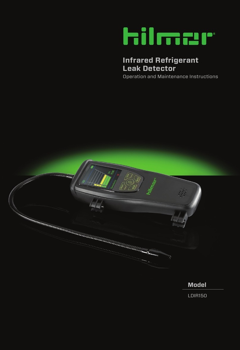
hilmor LDHD250 Troubleshooting guide

Model
LDHD250
Heated Diode Refrigerant
Leak Detector
Operation and Maintenance Instructions

2
TABLE OF CONTENTS
Introduction ......................................................................................................... 3
Key Features........................................................................................................ 4
Safety ..................................................................................................................... 5
Leak Detector Components........................................................................... 6
Features ............................................................................................................ 7-8
Operating Instructions............................................................................... 9-10
Technical Specifications .................................................................................11

3
INTRODUCTION
The hilmor Heated Diode Leak Detector oers the greatest sensitivity
and fastest response of any portable refrigerant detector available. This
is achieved through the use of a highly sensitive semi-conductive sensor
combined with a sophisticated microprocessor-controlled circuit. In
addition to the superior performance and functional advantages, it oers
a uniquely designed ergonomic shape to provide greater ease of use and
comfort.
WARNING:
It is important to read the entire instruction manual carefully in order
to gain a complete understanding of the tool's features, limitations
and specifications before use. hilmor products are designed and
manufactured to be used by trained and licensed HVAC/R technicians.
Incorrect application could result in accidents, injuries or death. Refer to
page 5 for safety warnings.

4
KEY FEATURES
ADDED CONVENIENCE
•Audible and visual notification for leak detection.
EASY TO READ
•LED screen for easy to read display.
ADDED VERSATILITY
•Works on all halogenated refrigerants.
SMALL SPACE CAPABLE
• Flexible probe allows access to the hard-to-reach areas.

5
SAFETY
SAFETY PRECAUTIONS
To prevent personal injury, please read the operating manual carefully and
operate only as instructed by following the guidelines listed below.
1. Wear safety glasses, gloves and all other recommended safety gear
when working with refrigerants. Contact with refrigerants may cause
injury. Please see any warnings associated with refrigerants.
2. Avoid the inhalation of refrigerant. High concentrations of refrigerants are
harmful to humans and can cause serious injury.
3. Do not allow probe to come in contact with electrically charged objects
or high voltage.
4. Before each use, make sure the probe tip is clean. Do not allow any
liquids to enter the probe tip; doing so will damage the unit.

6
8
Audio Mute Indicator
13
Sensor Indicator
9
Battery Voltage Indicator
14
Display During Warm Up
10
Real Time Detection Indicator
11
Gas Flow Indicator
12
Sensor Error Indicator
1
ON/OFF Button
2
SENS Button
3
RESET Button
4
MUTE Button
5
Panel Display
6
Sensor (Inside Probe Tip)
7
Flexible Probe
LEAK DETECTOR
COMPONENTS
1
23
4
5
7
6
9
8
10
11
12
14
13
FIG. 1
FIG. 2

7
FUNCTIONS AND FEATURES
The product is easy to operate and simplifies the user interface. Please
refer to FIG. 1 to familiarize yourself with the indicators and keypad
controls as you proceed through this section.
BATTERY VOLTAGE INDICATOR
The Battery Voltage Indicator allows the user to see the battery
level. If the indicator is o, the batteries are in full power; If the indicator
is on, the batteries have enough voltage for operation; If the indicator is
flashing rapidly, replace the batteries.
AUTOMATIC CIRCUIT/RESET FEATURE
Upon initial power-on and completion of the warm-up, the unit automatically
sets itself (automatic circuit) to ignore the level of refrigerant present at
the tip. Only a reading greater than this level will cause a notification.
NOTE: Since this feature causes the unit to ignore any refrigerant
present at the sensor tip after warm-up is complete, the unit should be
powered on and allowed to warm up in fresh air, to achieve maximum
sensitivity.
Reset feature: Resetting the unit during operation performs a
similar function; it programs the circuit to ignore the level of refrigerant
present at the tip. Each time the RESET button is pressed, as you move
closer to the leak, the unit sets its threshold for detection to a level
above the current concentration being detected. By moving closer
to a large leak and pressing RESET each time a full detection
is indicated, the user can pinpoint the source of the leakage.
Similarly, the unit can be moved to fresh air and reset for
maximum sensitivity. Resetting the unit with no refrigerant present
(fresh air) causes any level above zero to be detected. Each time the
RESET button is pressed, the LED displays “8” for about five (5) seconds
to provide a visual confirmation of the reset action.
SENSOR STATUS INDICATOR
The device automatically diagnoses and indicate the sensor’s status.
When on, the circuit automatically senses the condition of the sensor and
can indicate a failed or missing sensor.
If the circuit detects a failed or missing sensor, the display will show
and the leak detector will stop working. Please see "Cleaning Probe Tip"
on page 10.
FEATURES

8
AUDIBLE / VISUAL ALARMS – MUTE FEATURE
The unit features two notification indications – an internal speaker
audible alarm and LED screen data visual alarm. When a leak is detected
the LED screen displays the leakage level. When the device is powered ON,
the audible indication is deactivated by default. The audible alarm may be
enabled by pressing the MUTE button, allowing the audible as well as
visual indication. Press the MUTE button again to disable the audible
alarm.
SENSITIVITY ADJUSTMENT
The LHHD250 has six (6) levels of sensitivity adjustment. When the
SENS button is pressed, the sensitivity is displayed in the Real
Time Detector Indicator area on the panel display as a number (1-6)
for 3 seconds and then goes back to a flashing real time indication. 1 is the
lowest sensitivity and 6 is the highest.
BUTTON OPERATION
ON/OFF Press and hold for 2 seconds to turn the device “on” and
“o”.
RESET Reset sensitivity benchmark to improve stability and
sensitivity.
MUTE Press to toggle the audible alarm “on” and “o”.
SENS Press button to cycle through six (6) levels of sensitivity.
FEATURES (CONT.)

9
Keep the device away from moisture and high voltages.
To detect leakage in a system, the system must operate at a minimum
of 50 PSI. Environmental temperatures lower than 59°F (15°C) may
further reduce a system’s operating pressure, causing a leak to become
more dicult to detect. In such cases, “No Leak” may be falsely indicated,
requiring an alternate diagnostic means.
1. Turn on the unit by pressing and holding for 2 seconds then release
ON/OFF button.
2. The unit warms up and calibrates for approximately 30 seconds,
during which the middle LED will flash “-”, and “gas flow indicator”,
“and warm-up”, indicators will be on. Keep the LDHD250 away from
any areas of potential refrigerant leakage until the warm-up and
calibration period is over to achieve maximum sensitivity.
3. After warm-up, it displays a blinking “0” and the device is ready for use.
Press MUTE button to enable audible indication if desired, and the
device will emit a stable beeping.
4. Set the sensitivity level by pressing the SENS button according to
user’s demand, as described in the Sensitivity Adjustment Section, on
page 8.
5. Begin searching for refrigerant. Move the probe tip toward the
suspected leak. The flexible probe may be shaped to provide access to
hard-to-reach areas. The tip of the probe may need to be within 1/4”
(0.64cm) of a small leak to detect it.
NOTE: If the device has previously been used, make sure that the
probe tip is not obstructed with dirt, grease, etc. See "Cleaning Probe
Tip" on page 10.
6. If refrigerant is detected, the device will begin to notify – the audible
tone will quicken and it displays number of leakage level. As the
concentration of the leak increases, the audible tone will increase in
cadence and the number on the display will begin to increase. Leaking
areas are usually covered with contaminants such as compressor oil
or dirt. Be careful not to contact such contaminants with the probe tip.
OPERATING INSTRUCTIONS

10
OPERATING INSTRUCTIONS (CONT.)
7. If notification occurs before the leak source is pinpointed, the RESET
button may be used to pinpoint the leak, as described in the Automatic
Circuit/Reset Feature section, page 7. The unit may be reset as many
times as necessary to pinpoint the leak source. It is suggested to wait
for about five (5) seconds to detect the leakage after pressing RESET.
Likewise, in areas where the atmosphere is contaminated with refrigerant,
press reset key to “ignore” the leakage in the background. Make sure
not move the sensor tip away from the contaminated background while
resetting the detector.
BATTERY INSTALLATION
Hold the device tightly with two hands. Press the battery cover, drag
outward and remove it. Install the batteries into to the compartment and
close the cover. Note the proper battery orientation (polarity) of the
batteries during installation.
CLEANING PROBE TIP
Warning: Turn o device before cleaning the sensor.
Warning: The sensor may be hot after use. Please wait until sensor is the
same as the environmental temperature.
Keep the sensor tip clean: Remove probe tip by unscrewing it. Use cotton
cloth or dry air to clean the shield on the sensor tip if it gets contaminated.
If the probe tip itself is contaminated, soak the tip in absolute alcohol for
a few minutes, and then use compressed air to blow it dry, or dry it with a
clean cloth.
NOTE: Never use strong solvents such as gasoline, mineral oil, or
turpentine, as these solvents may coat the sensor with a thin film and
reduce the sensitivity of the detector. DO NOT clean sensor!
STORAGE
Store the detector and the sensor in a dry (less than 80% RH) and clean
location. Remove the batteries if the detector is not used for more than a
month.

11
TECHNICAL SPECIFICATIONS
Sensor Type: Semi-Conductive Sensor (Heated Diode)
Sensor Life:
5 years (typical)
Maximum Sensitivity: 4 grams/year
Response Time: ~3 seconds
Warm-Up Time: ~30 seconds
Operating Environment:
32°F (0°C) to 104°F (40°C) at <75%RH (non-condensing)
Display Method: LED Display
Notification Mode: LED Display and Audio
Battery: 3 1.5V AA
Battery Saver: Automatic shutdown after 10 minutes of inactivity
Working Time: ~6 hours
Certifications: SAE J1627, SAE J2791, SAE J2913, EN14624: 2012
Refrigerants Detected: It will detect to all halogenated (including Chlorine and
Fluorine) refrigerants. This includes, but is not limited to:
CFC: R12, R11, R500, R503
HCFC: R22, R123, R124, R502
HFC: R134A, R404A, R410A, R407C
Weight: 14 oz. (397g)
Size:
10.25" X 2.25" X 2.25" (260.35mm X 57.15mm X 57.15mm)

hilmor.com + 1-800-995-2222
©2019 hilmor
Table of contents
Other hilmor Security Sensor manuals