manuals.online logo
Brands
  1. Home
  2. •
  3. Brands
  4. •
  5. Satel
  6. •
  7. Security Sensor
  8. •
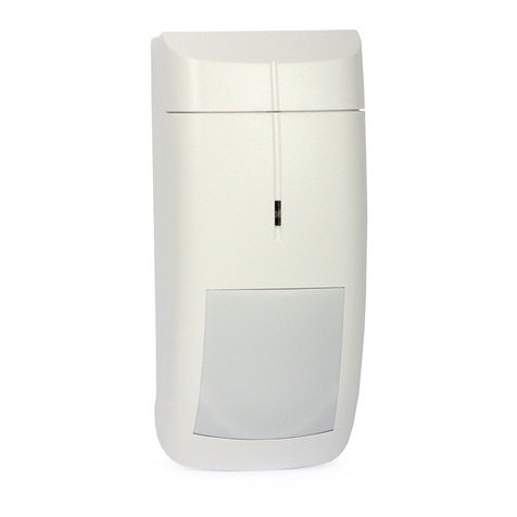
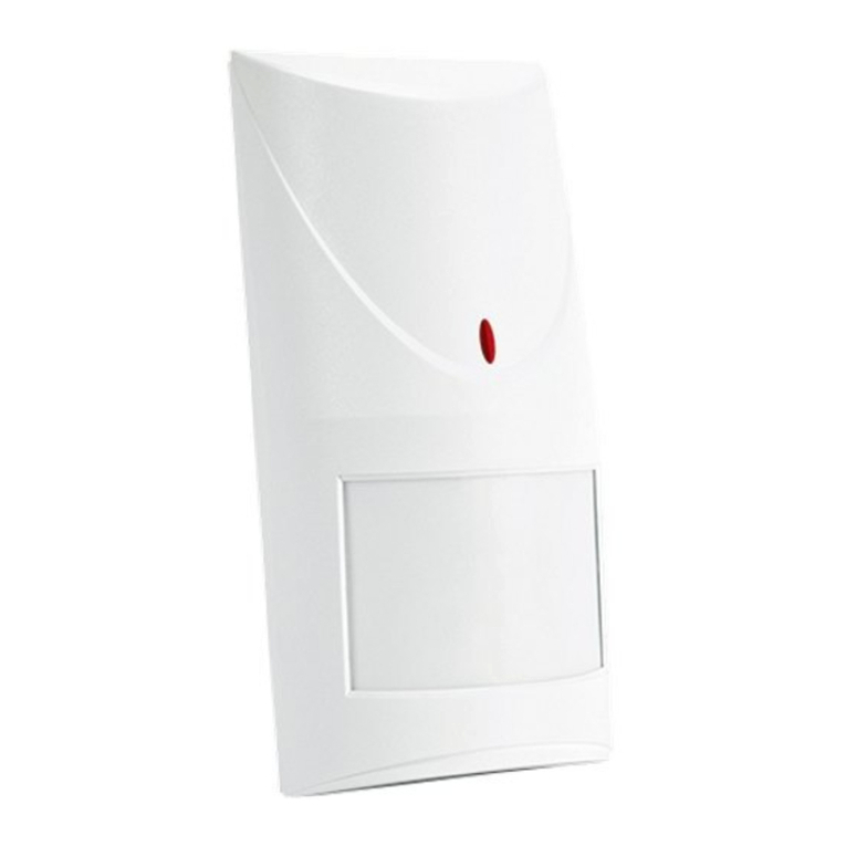
  9. Satel AQUA User manual

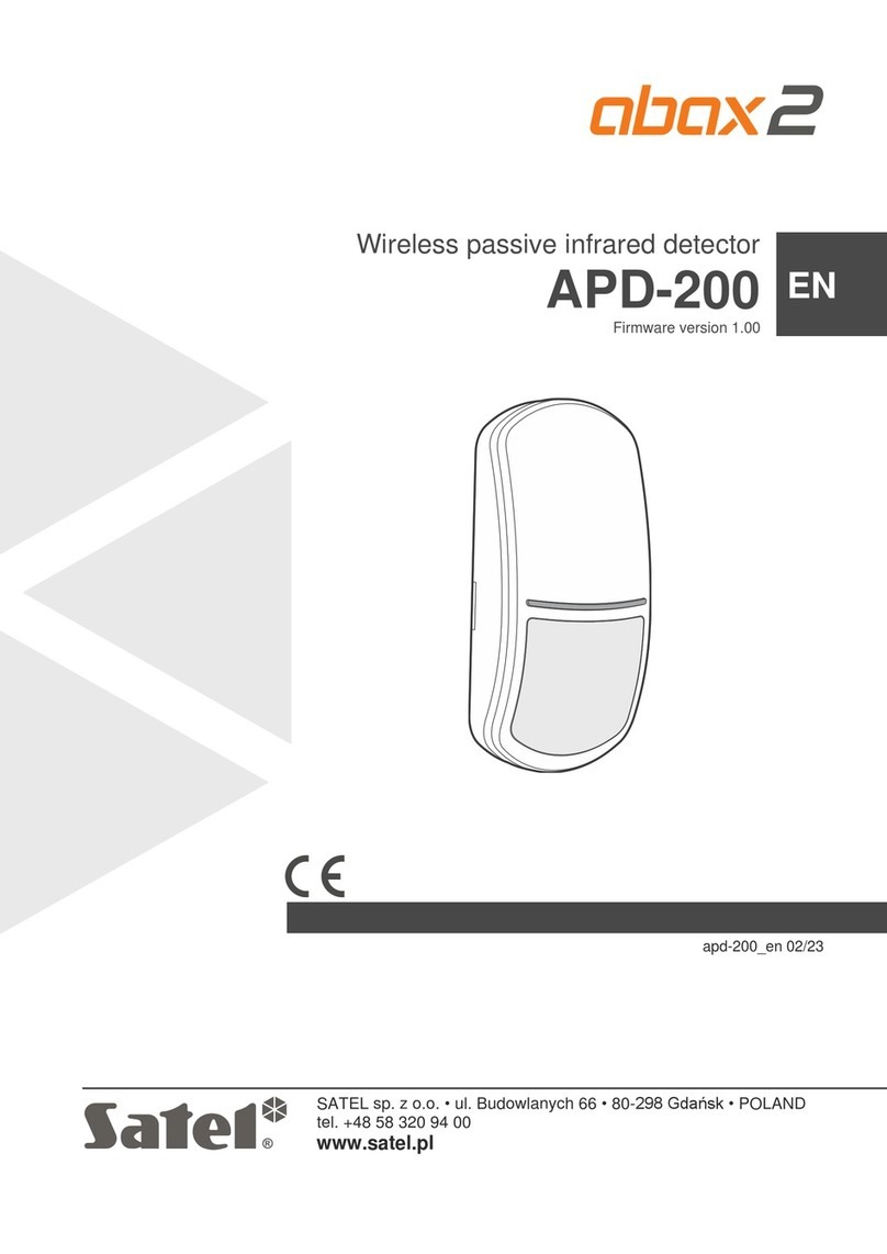
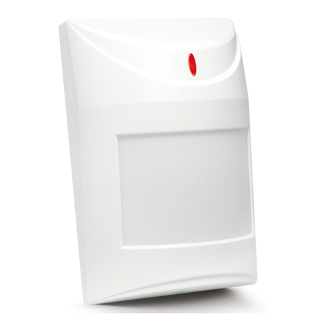
Satel AQUA User manual

®
DIGITAL PASSIVE
INFRARED DETECTORS
AQUA &AQUA Pro
aqua_dwa_e 06/04
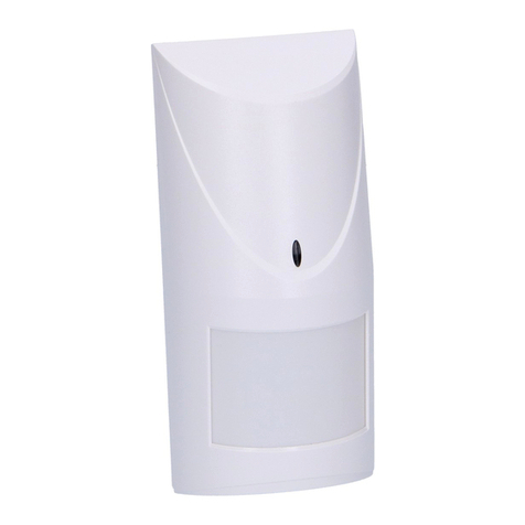
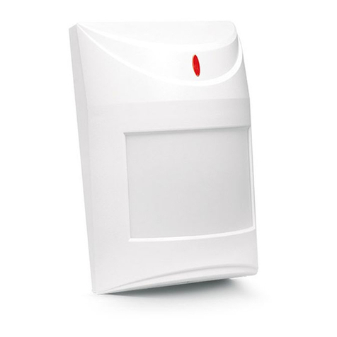
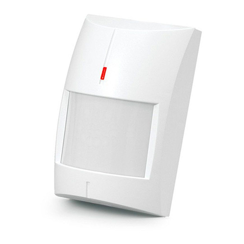
The microprocessor-based, fully digital
AQUA series detectors feature high
sensitivity and interference resistance.
The AQUA detector employs a dual
pyro electric element, and the
AQUA Pro - a quad element.
CONTACTS:
NC - alarm relay (NC)
TMP - tamper contact (NC)
COM - ground (0V)
12V - supply input (9-16V DC)
Three pairs of pins are used for setting
the detector working parameters (see
Table). The LED lights red for approx. 2s when
the detector is actuated, which enables
the installer to check the detector for
correct functioning and to
approximately determine the protected
area.
The detector features a prealarm
function. The prealarm does not
actuate the relay and is indicated by
a short flash of the LED, lasting
approx. 120ms. It is activated when the
ambient disturbances recorded by the detector do not meet the alarm criteria. The
prealarm sensitivity is not affected by the detector sensitivity, which is set with jumpers.
For 30 seconds after the power is turned on, the detector remains in a starting state,
which is signalized by rapid LED blinking. Only then the detector enters its operational
readiness state.
The detector monitors the supply voltage. If the voltage drops below 9V (±5%) for more
than 2 seconds, the detector will signalize a violation state until a voltage of minimum 9V
(±5%) is restored.
INSTALLATION
The detector is designed for indoor installation. It can be mounted on the wall, either
directly or on the included holder. Prior to installation of the detector housing, remove the
electronics board and make adequate openings for screws and cable in the rear panel of
the housing. It is advisable that you exercise particular care to prevent the pyro
element from getting dirty or damaged during installation.
The scale provided on the detector board (see Fig.1) is intended for properly setting the
pyro element against the lens installed in the housing. If the detector is to be mounted at
JP1 JP2 JP3
Low sensitivity
Medium sensitivity
High sensitivity
LED indicator ON
LED indicator OFF
- pins open - pins shorted
LED
NC NC TMP TMP COM 12V
PIR SENS.
LED ON/OFF
JP1
JP2
JP3
pyro element
tamper contact
relay
positioning scale operating parameter
setting pins
Figure 1. View of detector electronics board
a height of 2.1 m, set the board so that the midline is aligned with the mark provided on
the housing next to the scale. Such a setting will ensure that the manufacturer specified
range is obtained. In case the
detector is to be installed at another
height, it is necessary to carry out
regulation of the pyro element
setting by moving the board up
(when the detector hangs higher
than 2.1m) or down (when the
detector hangs lower than 2.1m) in
relation to the mid-position.
Figure 2 shows typical examples of
connecting the detectors in EOL
(parameter) configuration and 2EOL
(two-parameter) configuration.
Resistors should be mounted inside
the detector housing.
LENSES
In the detector is mounted the wide angle lens, however, it is possible to replace it by
another lens with different characteristics (range, number of beams, angle of view).
Lenses are available with the following characteristics:
It. Lens type Range Angle of view
1 wide angle 9m 101°
2 extra wide angle 15m 141.2°
3 long-range with access zone
monitoring 30m main beam – 3m wide (at the end of range)
4 vertical barrier 22.5m 2.2m wide (at the end of range)
NOTE: The detector operating range should be selected to match the size of space
where the detector will be installed. The size of the space along the main
direction of detector positioning is not to be less than 1/3 the nominal range of
the detector. Improper selection of the lens may cause excessive sensitivity
and trip false alarms.
TECHNICAL DATA
Nominal supply voltage.......................................................................................... 12V DC
Mean power consumption (±10%)............................................................................. 9.5mA
Violation signaling time....................................................................................................2s
Operating temperature range ........................................................................... -10...+50°C
Detectable motion speed...................................................................................up to 3 m/s
Dimensions ...................................................................................................63x96x49mm
Recommended installation height................................................................................2.1m
Figure 2. Examples of detector connection
2R
NC NC TMP TMP COM 12V
AQUA detector
NC NC TMP TMP COM 12V
AQUA detector
Z2 - programmed as „24h TAMPER” – NC type
+12V COM Z1 Z2 COM Z3 Z4 COM Z5 Z6 COM Z7 Z8 COM
R R
Latest EC declaration of conformity and product approval certificates can
be downloaded from our Web site www.satel.pl
Figure 3. Distribution of beams and operating range of detector with wide angle lens
2.1 m
1 m 2.9 m 5.8 m 9 m
SIDE VIEW:
7 m
0
7 m
TOP VIEW:
101°
SATEL sp. z o.o.
ul. Schuberta 79
80-172 Gdańsk
POLAND
tel. + 48 58 320 94 00
[email protected]
www.satel.pl

This manual suits for next models

2

Other Satel Security Sensor manuals

Satel APMD-150 User manual

Satel

Satel APMD-150 User manual

Satel SLIM-PIR-PRO User manual

Satel

Satel SLIM-PIR-PRO User manual

Satel OPAL-GY User manual

Satel

Satel OPAL-GY User manual

Satel abax 2 ACD-220 User manual

Satel

Satel abax 2 ACD-220 User manual

Satel AFD-100 User manual

Satel

Satel AFD-100 User manual

Satel OPAL User manual

Satel

Satel OPAL User manual

Satel AQUA S User manual

Satel

Satel AQUA S User manual

Satel AGD-100 User manual

Satel

Satel AGD-100 User manual

Satel AQUA LUNA User manual

Satel

Satel AQUA LUNA User manual

Satel abax2 User manual

Satel

Satel abax2 User manual

Satel PDB-100 User manual

Satel

Satel PDB-100 User manual

Satel AGD-100-BR User manual

Satel

Satel AGD-100-BR User manual

Satel SX6-TO User manual

Satel

Satel SX6-TO User manual

Satel AVD-100 User manual

Satel

Satel AVD-100 User manual

Satel AVD-100 User manual

Satel

Satel AVD-100 User manual

Satel AOD-200 User manual

Satel

Satel AOD-200 User manual

Satel COBALT Pro User manual

Satel

Satel COBALT Pro User manual

Satel OPAL Plus User manual

Satel

Satel OPAL Plus User manual

Satel OPAL Pro User manual

Satel

Satel OPAL Pro User manual

Satel TD-1 User manual

Satel

Satel TD-1 User manual

Satel micra MXD-300 User manual

Satel

Satel micra MXD-300 User manual

Satel AQUA PRO User manual

Satel

Satel AQUA PRO User manual

Satel XD-2 User manual

Satel

Satel XD-2 User manual

Satel GRAPHITE User manual

Satel

Satel GRAPHITE User manual

Popular Security Sensor manuals by other brands

STL MWS-Ex-DC quick start guide

STL

STL MWS-Ex-DC quick start guide

DirekTronik LDDS20 user manual

DirekTronik

DirekTronik LDDS20 user manual

Baumer UNAM 12N3914/S14 operating instructions

Baumer

Baumer UNAM 12N3914/S14 operating instructions

ARCTIC HAYES AHATEX12 user manual

ARCTIC HAYES

ARCTIC HAYES AHATEX12 user manual

AJAX CombiProtect user manual

AJAX

AJAX CombiProtect user manual

Bosch Analog Detector Series Installation and operation guide

Bosch

Bosch Analog Detector Series Installation and operation guide

PCB Piezotronics ICP 123B23 Installation and operating manual

PCB Piezotronics

PCB Piezotronics ICP 123B23 Installation and operating manual

PCB Piezotronics 8120-400A Installation and operating manual

PCB Piezotronics

PCB Piezotronics 8120-400A Installation and operating manual

Niko DALI-2 BMS 41-742 user manual

Niko

Niko DALI-2 BMS 41-742 user manual

GJD GEM manual

GJD

GJD GEM manual

GJD D-TECT 1 HT manual

GJD

GJD D-TECT 1 HT manual

Profort vibraSpot manual

Profort

Profort vibraSpot manual

Mosentek MS033C manual

Mosentek

Mosentek MS033C manual

MSA WORKMAN MINI PFL Use and maintenance instructions

MSA

MSA WORKMAN MINI PFL Use and maintenance instructions

Berthold GAMMAcast LB 6739 operating manual

Berthold

Berthold GAMMAcast LB 6739 operating manual

PPA F10R instruction manual

PPA

PPA F10R instruction manual

Thytronic SME2-IS Installation

Thytronic

Thytronic SME2-IS Installation

Bosch Photobeam 3000 ISC-FPB1-W30DS installation guide

Bosch

Bosch Photobeam 3000 ISC-FPB1-W30DS installation guide

manuals.online logo
manuals.online logoBrands
  • About & Mission
  • Contact us
  • Privacy Policy
  • Terms and Conditions

Copyright 2025 Manuals.Online. All Rights Reserved.