Afriso EURO-INDEX LAG-14 ER User manual
Mess-, Regel- und
Überwachungsgeräte
für Haustechnik,
Industrie und Umweltschutz
Lindenstraße 20
74363 Güglingen
Telefon
+49 7135 102-0
Service
+49 7135-102-211
Telefax
+49 7135-102-147
www.afriso.com
Read instructions before using device!
Observe all safety information!
Keep instructions for future use!
07.2019.1
854 001 0153
Operating instructions
Leak detector
LAG-14 ER
0123
MVV TB C 2,
App. C 2.15.16

2 LAG-14 ER
Table of contents
1This instruction manual ............................................................................................. 4
1.1 Precautions .................................................................................................... 4
2Safety ......................................................................................................................... 5
2.1 Intended use................................................................................................... 5
2.2 Predictable incorrect application ................................................................... 5
2.3 Safe handling ................................................................................................. 6
2.4 Qualification of personnel .............................................................................. 6
2.5 Modifications to the product........................................................................... 7
2.6 Usage of spare parts and accessories.......................................................... 7
2.7 Liability information ........................................................................................ 7
3Product description.................................................................................................... 8
3.1 Application area ...........................................................................................10
3.2 Function........................................................................................................10
3.3 Operating modes ......................................................................................... 12
3.4 Application examples...................................................................................12
4Technical data .........................................................................................................14
4.1 Approvals, tests and conformities ...............................................................16
5Transport and storage.............................................................................................17
6Mounting and commissioning..................................................................................17
6.1 Calculation fundamentals ............................................................................17
6.2 Installing the container for the leak detection fluid......................................20
6.3 Minimum distance ........................................................................................21
6.4 Pipe installation ............................................................................................22
6.5 Mounting the test valve................................................................................24
6.6 Mounting the control unit ............................................................................. 24
6.7 Electrical connection....................................................................................26
6.8 Commissioning the product .........................................................................30
7Operation .................................................................................................................31
7.1 Alarm condition ............................................................................................ 31
7.2 Function test.................................................................................................32
8Maintenance ............................................................................................................33
8.1 Maintenance times.......................................................................................33
8.2 Maintenance activities .................................................................................33
9Troubleshooting....................................................................................................... 34
10 Decommissioning, disposal.....................................................................................34
11 Spare parts and accessories...................................................................................36

LAG-14 ER 3
12 Leak detection fluids for leak detector ....................................................................37
13 Warranty...................................................................................................................37
14 Copyright..................................................................................................................37
15 Customer satisfaction..............................................................................................37
16 Addresses ................................................................................................................37
17 Appendix ..................................................................................................................38
17.1 Certification of specialised company (according to applicable water
regulations)...................................................................................................38
17.2 Approval documents ....................................................................................39
17.3 EU Declaration of Conformity ......................................................................40
17.4 Declaration of Performance (DoP) ..............................................................41
17.5 CE Marking...................................................................................................42

This instruction manual
4 LAG-14 ER
1 This instruction manual
These operating instructions are part of the product.
Read this manual before using the product.
Keep this manual during the entire service life of the product
and always have it readily available for reference.
Always hand this manual over to future owners or users of the
product.
1.1 Precautions
WARNING
WORD
Type and
source of the hazard are shown here.
Precautions to take in order to avoid the hazard are shown here.
There are three different levels of warnings:
Warning word Meaning
DANGER Immediately imminent danger!
Failure to observe the information will result in
death or severe injuries.
WARNING Possibly imminent danger!
Failure to observe the information may result in
death or severe injuries.
NOTICE Failure to observe the information may result in
damage to property.

Safety
LAG-14 ER 5
2 Safety
2.1 Intended use
The leak detector LAG-14 is a leak detector for liquid-based systems
as per EN 13160-1, class II (EN 13160-3).
The LAG-14 ER leak detector may only be used to monitor double-
walled containers (tanks) as per chapter 3.1, page 10 containing leak
detection fluid in the interstitial space and used for the aboveground
storage of:
•Water-polluting liquids
•Flammable liquids with a flash point of > or ≤55 °C.
Since July 2003, the LAG-14 ER leak detector may only be used for
replacement deliveries for underground, double-walled tanks as a re-
sult of the reclassification of water-polluting liquids in Germany.
Leaks in the container (tank) are detected and signalled when the
level of the leak detection fluid falls.
Only black containers may be installed in hazardous areas (Ex).
Any use other than the application explicitly permitted in this instruc-
tion manual is not permitted.
2.2 Predictable incorrect application
The control unit must never be used in the following cases:
•Hazardous area (Ex)
If the product is operated in hazardous areas, sparks may cause
deflagrations, fires or explosions.
The intrinsically safe circuit and the corresponding probe may be op-
erated in hazardous areas (EX), zone 0, zone 1 and zone 2.
White containers must not be installed in hazardous areas (Ex).

Safety
6 LAG-14 ER
2.3 Safe handling
The leak detector LAG-14 ER represents state-of-the-art technology
and is made according to the pertinent safety regulations. Each prod-
uct is subjected to a function and safety test prior to shipping.
Operate the leak detector LAG-14 ER only when it is in perfect
condition. Always observe the operating instructions, all perti-
nent local and national directives and guidelines as well as the
applicable safety regulations and directives concerning the pre-
vention of accidents.
DANGER
Severe burns or death caused by mains voltage (AC
230 V,
50
Hz) in the control unit.
Do not expose the control unit to water.
Disconnect the mains voltage supply before opening the control
unit or before performing maintenance and cleaning work and
make sure it cannot be switched on.
Do not tamper with the control unit in any way whatsoever.
Observe the instructions in DIN EN 60079-10-1.
Malfunctions which may have an adverse effect on safety must
be immediately repaired.
2.4 Qualification of personnel
The product may only be mounted, commissioned, operated, main-
tained, decommissioned and disposed of by specially qualified com-
panies. These are specialised companies as per § 3 of the German
Ordinance on Installations for Handling Water-Polluting Substances
April 18, 2017 (German Federal Law Gazette (BGBI.) I p. 377).
These activities do not have to be performed by specialised compa-
nies if this obligation does not apply according to the applicable local
directives or if AFRISO performs these activities with AFRISO's own,
trained staff.
If handling tanks containing liquids with a flash point of ≤55° C, the
staff must also be knowledgeable in fire and explosion protection.
Electrical work may only be performed by trained electricians and in
compliance with all applicable local and national directives, regula-
tions and electrical code requirements.

Safety
LAG-14 ER 7
2.5 Modifications to the product
Changes or modifications made to the product by unauthorised per-
sons may lead to malfunctions and are prohibited for safety reasons.
2.6 Usage of spare parts and accessories
Usage of unsuitable spare parts and accessories may cause dam-
age to the product.
Use only genuine spare parts and accessories of the manufac-
turer (see chapter 11, page 36).
2.7 Liability information
The manufacturer shall not be liable in any form whatsoever for
direct or consequential damage resulting from failure to observe the
technical instructions, guidelines and recommendations.
The manufacturer or the sales company shall not be liable for costs
or damages incurred by the user or by third parties in the usage or
application of this product, in particular in case of improper use of the
product, misuse or malfunction of the connection, malfunction of the
product or of connected products. The manufacturer or the sales
company shall not be liable for any damage whatsoever resulting
from any use other than the use explicitly permitted in this instruction
manual.
The manufacturer shall not be liable for misprints.

Product description
8 LAG-14 ER
3 Product description
The leak detector consists of a control unit, a probe and a container
for leak detection fluid (black LAG container).
The control unit and the probe are connected by means of a two-wire
signal cable with a maximum length of 50 m.
The probe is plugged into the top of the black LAG container. In the
case of a leak in the interstitial space, the leak detection fluid level in
the black LAG container falls. The electrode rods of the probe are no
longer submerged in the leak detection fluid. The control unit detects
the change in resistance and generates an alarm.
Fig. 1: Container for leak detection fluid (black LAG container) with
probe
a
Liquid level
d
Housing part
B
Company and approval mark
e
Electrode rods
c
Signal cable

Product description
LAG-14 ER 9
Probe
The probe consists of two metallic electrode rods which are installed
at a specific distance from each other.
The two electrode rods are contained in a housing with a diameter of
34 mm which also holds the probe in the black LAG container. The
probe is equipped with a two-wire signal cable, length 1 m.
Control unit
The control unit SE2 contains the following elements in an impact-
resistant plastic housing: display elements and controls as well as all
electronic components for signal processing and conversion of the
probe signal into a digital output signal.
The output signal is available as a voltage-free relay contact.
a
Green pilot lamp
B
Test button
c
Red alarm lamp
d Acknowledge
button
e Without function
Fig. 2: Control unit
Product description
10 LAG-14 ER
3.1 Application area
Tanks
Only the following tanks are approved: double-walled containers
(tanks) which are operated under atmospheric conditions and which
comply with the standards DIN 6616 type A, DIN 6623-2, DIN 6624-
2, EN 12285-2 (type D) and EN 12285-1 (type D) or which have an
approval that the interstitial space is suitable for connection of a liq-
uid-based leak detection system.
The interstitial space volume of the system must not exceed 1 m³.
Stored liquids
Only the following liquids are approved:
•Water-polluting liquids.
•Flammable liquids with a flash point of > or ≤55 °C.
Approved storage media
If the containers (tanks) are operated under atmospheric conditions
and depending on the design of the containers (tanks), water-pollut-
ing liquids with the following densities may be stored in the contain-
ers (tanks):
•Tanks as per DIN 6616 type A, DIN 6623-2 and DIN 6624-2
≤2.5 m Ø permissible density ≤1.90 g/cm³
≤2.9 m Ø permissible density ≤1.85 g/cm³
CAUTION
Danger of reaction of leak detection fluid and stored liquid if un-
suitable leak detection fluid is used.
The leak detection fluid and the stored liquid may not react.
Proven compatibility is required.
Observe the information on the intended use in chapter 2.1,
page 5.
3.2 Function
The LAG-14 ER leak detector monitors the interstitial space of dou-
ble-walled tanks filled with leak detection fluid. In the case of a leak
in the inner or outer wall of the container (tank), above or below the
levels of the stored liquid or the ground water, the leak detection fluid
escapes. This causes the level of the leak detection fluid to fall. The
electrode rods of the probe are no longer submerged in the leak de-
tection fluid. The control unit detects the change in resistance, gener-
ates visual and audible alarms and actuates the output relay.

Product description
LAG-14 ER 11
Probe
The black LAG container is installed above the interstitial space. The
bottom side of the black LAG container is connected to the top of the
interstitial space via a hose. This way, the black LAG container is the
top part of the interstitial space. The interstitial space is filled with
leak detection fluid to the middle of the black LAG container. The
probe is installed from the top of the black LAG container so that the
electrode tips are covered by the leak detection fluid. Both electrodes
are connected to the control unit by a two-wire cable.
Control unit
The control unit continuously monitors the electrical resistance be-
tween the two electrodes of the probe. The green pilot lamp lights up
when the device is ready for operation. If the probe resistance is less
than 5 kΩ, there is no alarm condition: The red alarm lamp is off, the
relay is:
•De-energised (in the operating mode Eco)
•Energised (in the operating mode FailSafe)
If the resistance is greater than 5 kΩ, an alarm condition, i.e. a leak
has been detected by the control unit: The red alarm lamp and the
audible alarm are on and the relay is:
•Energised (in the operating mode Eco)
•De-energised (in the operating mode FailSafe)
The audible alarm can be muted with the "Acknowledge" button in
the case of an alarm.
No alarm is triggered in case of a power outage. When mains voltage
is restored, the product immediately resumes operation. If a leak has
occurred in the meantime, this is signalled.
The green pilot lamp lights up as soon as the leak detector is sup-
plied with mains voltage. The Test button allows you to simulate an
alarm condition in order to perform a function test.

Product description
12 LAG-14 ER
3.3 Operating modes
Eco:
The LAG-14 ER leak detector is equipped with an output relay to
transmit the alarm signal to additional external devices. If no error
condition is present, the relay is de-energised; in case of an alarm,
the relay is energised.
FailSafe:
The LAG-14 ER leak detector is equipped with an output relay to
transmit the alarm signal to additional external devices. If no error
condition is present, the relay is -energised; in case of an alarm, the
relay is de-energised.
The leak detector LAG-14 ER can be operated with or without addi-
tional external devices. External devices include units for audible and
visual alarm signal or remote alarm devices, building control sys-
tems, etc.
3.4 Application examples
1 Control unit
2 Probe cable
3 Black LAG con-
tainer
4 Probe
5 Connection line
6 Outer wall
7 Interstitial space
8 Inner wall
9 Test valve
Fig. 3: Standard application
Product description
LAG-14 ER 13
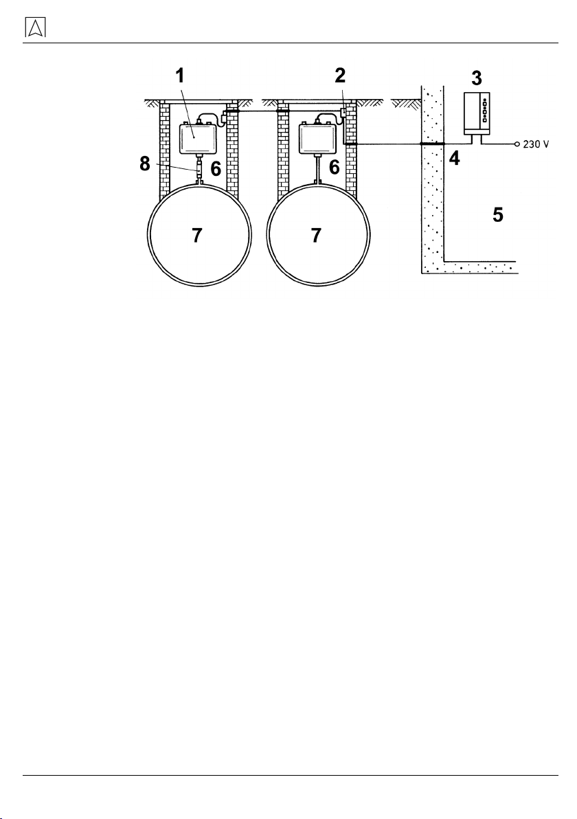
Fig. 4: Two black LAG containers at a single control unit (different
locations)
1 Black LAG containers, install
in recess, if possible
5 Non-hazardous (safe) area
2 Permanently installed junction
boxes, connect both probes in
series
6 Hazardous (Ex) area
3 Control unit 7 Stored liquid, compatible
with leak detection fluids
4 All ducts gastight in protective
pipe
8 Transparent piece, sealed
installation
No more than two black LAG containers with probes may be con-
nected in series to one control unit.
Technical data
14 LAG-14 ER
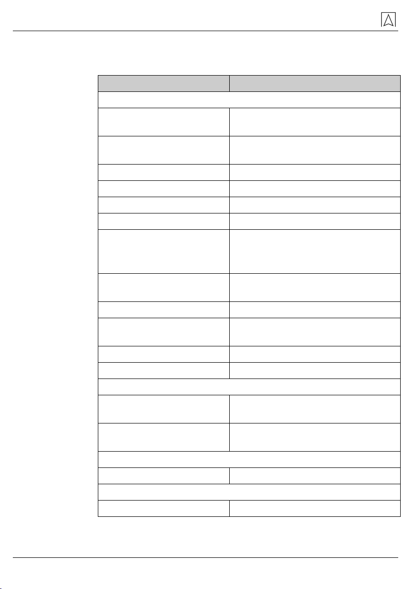
4 Technical data
Table 1: Technical specifications probe and container
Parameter Value
General specifications
Dimensions tank
(W x H x D)
300 x 325 x 145 mm
Space requirements
(W x H x D)
500 x 700 x 200 mm
Weight 1.0 kg
Electrode housing Plastic, Ø 34 mm
Electrode rods V 2 A, Ø 3 mm
Resistance Leak detection fluid
Connection cable:
Standard length
Max. length
H05VV-F, 2 x 1 mm²
1 m
50 m (shielded)
Container (conductive)
black
Hostalen / Vestolen
Surface resistance < 109Ohm as per DIN 53486
Active volume 4.5 litres
(electrode tip to liquid level)
Total volume 10 litres
Connecting hose EPDM hose 14 x 3 (ID 14)
Operating temperature range
Ambient -25 °C to +50 °C, depending
on mixing ratio
Storage -25 °C to +60 °C, depending
on mixing ratio
Supply voltage
Probe voltage Max. 17 V, AC
Electrical safety
Degree of protection IP 20 (EN 60529)

Technical data
LAG-14 ER 15
Table 2: Technical specifications control unit SE2
Parameter Value
General specifications
Dimensions housing
(W x H x D)
100 x 188 x 65 mm
Weight 0.4 kg
Equipment group
(2014/34/EU)
Category (2014/34/EU)
Type of protection
Protection class
Supply voltage
Safety-related maximum
voltage Um
Degree of protection
II
(1) G
[Ex ia] IIC
II
230 V, 50 Hz
253 V
IP 30
Response delay < 1 second
Additional connections 1 output relay (1 changeover contact)
Breaking capacity output
relay
Max. 250 V. 2 A, resistive load
Relay fuse T 2 A
Emissions The A-weighted sound level of the au-
dible alarm is at least 70 dB(A) at a
distance of one metre
Operating temperature range
Ambient -20 °C to +50 °C
Supply voltage
Nominal voltage AC 230 V ± 10 %, 50/60 Hz
Nominal power 5 VA
Mains fuse T 100 mA H (1.5 kA)
Electrical safety
Protection class II (EN 60730-1)
Degree of protection IP 30 (EN 60529)
Technical data
16 LAG-14 ER
Electromagnetic compatibility (EMC)
Emitted interference EN 60730-1:2011
Noise immunity EN 60730-1:2011
Probe circuits
Probe circuit
Maximum values
for subgroup IIC
for subgroup IIB
Effective internal capaci-
tance and inductance
ia
U0= 16.8 V, Ik= 57 mA, P = 240 mW,
linear characteristic
C0180 nF; L01 mH
C0675 nF; L08 mH
Negligible
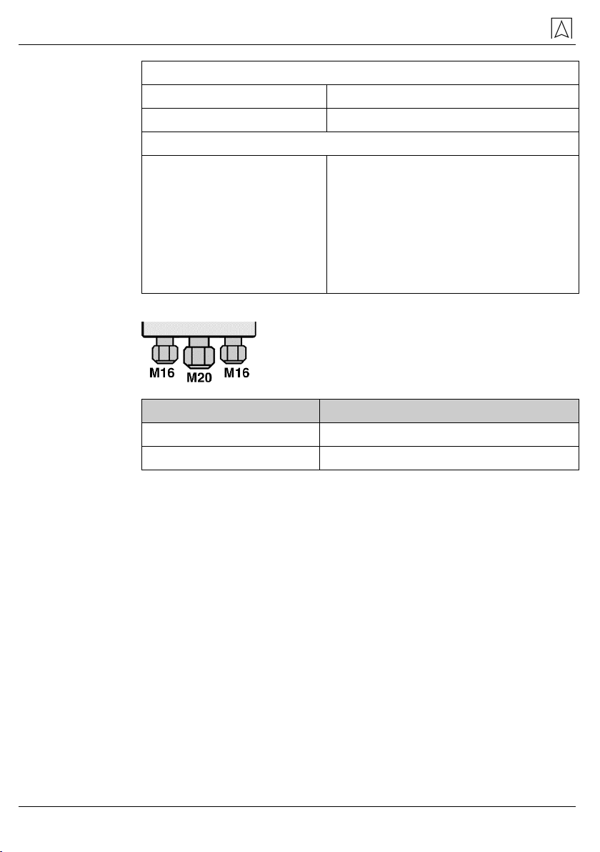
Cable glands at the control unit
The centre blind piece can be replaced with
a cable gland M20.
Cable gland Cable diameter
M16 4.0 - 8.8 mm
M20 8.0 - 12.5 mm
4.1 Approvals, tests and conformities
LAG-14 ER complies with the EMC Directive (2014/30/EU), the Low
Voltage Directive (2014/35/EU), the ATEX Directive (2014/34/EU),
the RoHS Directive (2011/65/EU), EC Type Examination Certificate
number EX5 11 02 15639 011 and the Construction Products Di-
rective 305/2011 (EN 13160-3:2003).
Transport and storage
LAG-14 ER 17
5 Transport and storage
CAUTION
Damage to the product due to improper transport.
Do not throw or drop the product.
Protect the product from wetness, humidity, dirt and dust.
CAUTION
Damage to the product due
to improper storage.
Protect the product from shock when storing it.
Store the product packaged in this film.
Store the product in a clean and dry environment.
Protect the product from wetness, humidity, dirt and dust.
Only store the product within the permissible temperature range.
6 Mounting and commissioning
6.1 Calculation fundamentals
LAG-14 ER at underground container (tank)
The effective capacity of the black LAG container is limited by the liq-
uid level screw in the centre of the container; it amounts to 4.5 litres.
For underground containers (tanks), 1 litre of leak detection fluid is
required in the black LAG container per 100 litres of interstitial space
volume.
The black LAG container is sufficient for 450 litres of interstitial space
volume. This corresponds to containers (tanks) with a storage vol-
ume of up to 60,000 litres.
Together with additional containers with an effective capacity of 4.5
litres each, the LAG14 ER leak detector can also be used for tanks
with a greater interstitial space volume.
The additional containers are connected to each other and to the
black LAG container by means of EPDM hoses.

Mounting and commissioning
18 LAG-14 ER
Leak detection fluid in the in-
terstitial space of the tank as
per nameplate on the tank
[litres]
Number of re-
quired black
LAG containers
with probe
Number of required
additional contain-
ers (without probe)
0-450 1 0
450-900 1 1
900-1350 1 2
1350-1800 1 3
1800-2250 1 4
In the case of new installations, the interstitial space volume of the
system must not exceed 1000 l.
LAG-14 ER at aboveground container (tank)
For aboveground containers (tanks), 1 litre of leak detection fluid is
required in the black LAG container per 35 litres of interstitial space
volume.
One black LAG container is sufficient for 157.5 litres of interstitial
space volume. This corresponds to containers (tanks) with a storage
volume of up to 20,000 litres.
Together with additional containers with an effective capacity of
4.5 litres each, the LAG-14 ER leak detector can also be used for
tanks with a greater interstitial space volume.
The additional containers are connected to each other and to the
black LAG container by means of EPDM hoses.
Leak detection fluid in the in-
terstitial space of the tank as
per nameplate on the tank
[litres]
Number of re-
quired black
LAG containers
with probe
Number of required
additional contain-
ers (without probe)
0-157.5 1 0
157.5-315 1 1
315-472.5 1 2
472.5-30 1 3
630-787.5 1 4
Mounting and commissioning
LAG-14 ER 19
Fig. 5: Additional container
1
Additional black container 6 Hazardous (EX) area or
non-hazardous (safe) area
2
Black LAG container with probe
3 Junction box, permanently in-
stalled
7 Communicating
connection
4
Control unit
5 Non-hazardous
(safe) area
Mounting and commissioning
20 LAG-14 ER
Dasverknüpfte Bild kann nicht angezeigt werden. Möglicherweise wurde die Datei verschoben, umbenannt oder gelöscht. Stellen Sie sicher, dass die Verknüpfung auf die korrekte Datei und den korrekten Speicherort zeigt.
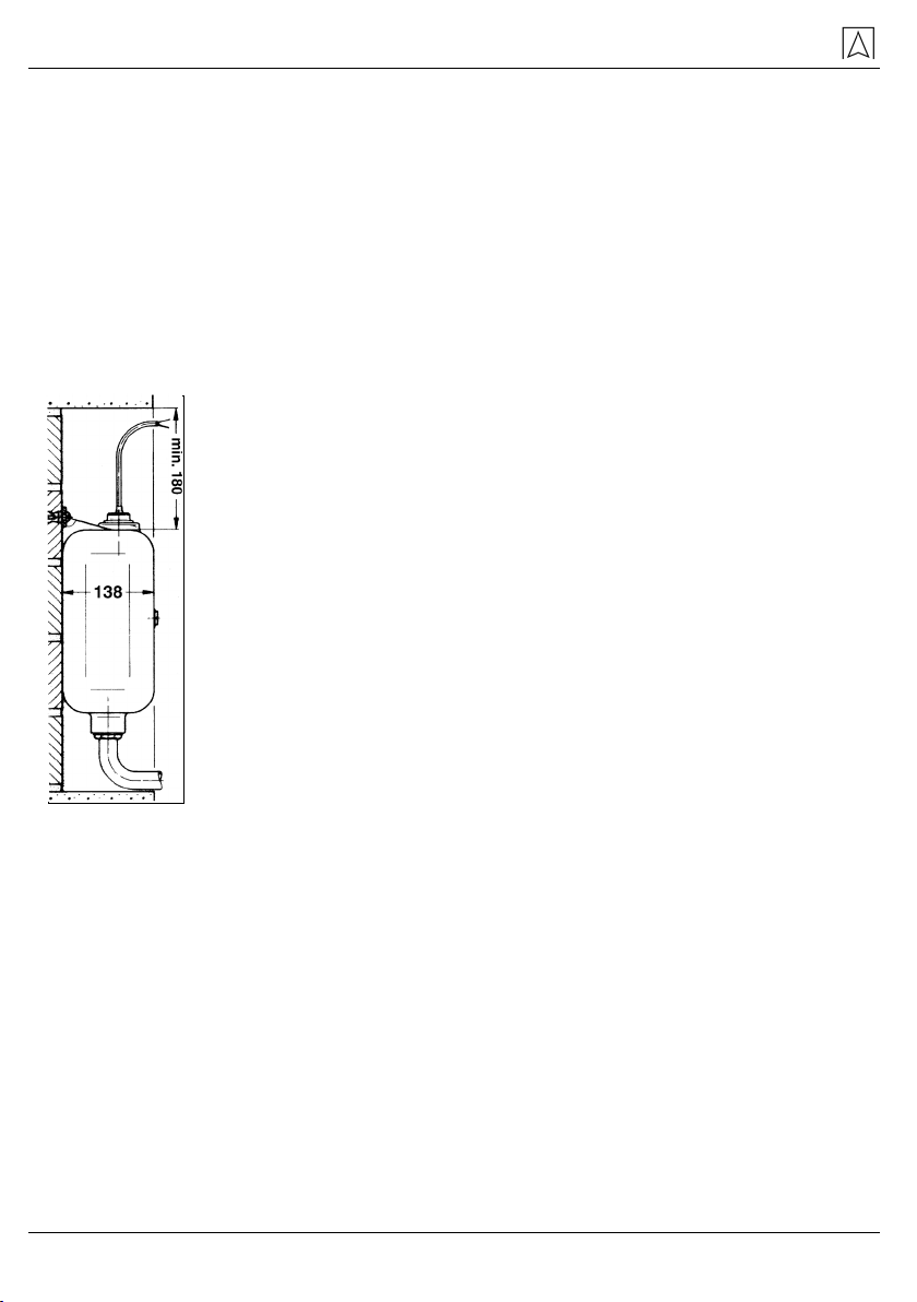
6.2 Installing the container for the leak detection fluid
Verify the volume of leak detection fluid required (check the
nameplate at the tank (container)) and determine the number of
required black LAG containers as described in chapter 6.1,
page 17).
The black LAG container can be mounted directly next to the control
unit or in the vicinity of the container (tank) to be monitored in haz-
ardous areas (Ex) zone 1 and zone 2 (e.g. in the manhole).
When installing the LAG container in the hazardous area (Ex),
in the manhole or outdoors, make sure neither surface water no
rain nor dirt nor airborne sand can get into the container or into
the cable junction box.
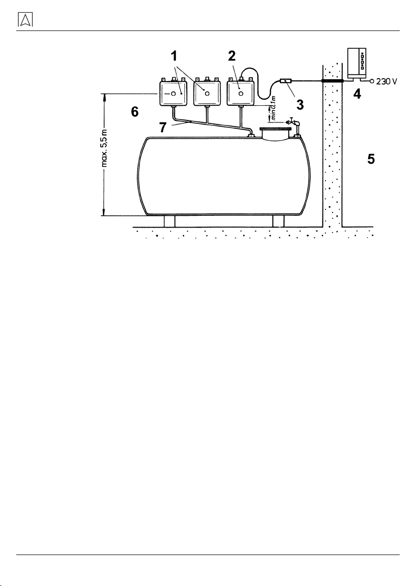
Mount the black LAG container high enough above the intersti-
tial space for the static pressure of the leak detection fluid to be
sufficient at all points of the interstitial space to cause the leak
detection fluid to escape and the leak detection fluid level in the
black LAG container to fall in the case of a leak so that an alarm
can be triggered.
The minimum distance between the tank top and the bottom of
the black LAG container primarily depends on the density of the
stored medium and, in the case of underground tanks, on the
possible level of the ground water or backflow above the tank
top. Mount the black LAG container at least 30 cm above the
tank top.
If the test pressure for the interstitial space of the tank is 0.6 bar,
the black LAG containers (with reference to the liquid level
screw) may be no higher than 5.5 m above the bottom of the
tank.
Table of contents
Other Afriso EURO-INDEX Security Sensor manuals


Popular Security Sensor manuals by other brands


Intelbras
Intelbras IVP 3000 PET user manual

DANLERS
DANLERS CBU-HBSP Installation

Monacor
Monacor IRS-200 quick guide

Larson Electronics
Larson Electronics MS-AT-7A-LV instruction manual

dtec
dtec GJD 350 Installation & setup guide

Thermo Scientific
Thermo Scientific Dionex UltiMate 3000 Series operating instructions


