HILO SELECT User manual

SELECT
SELECTSELECT
SELECT
Operator’s Manual
Rev.1.6
Apr 16, 2018.
MODEL: SELECT
HILO CO. LTD.
Japan
Kobe-hilo.co.jp / contact@kobe-hilo.co.jp

Revision Records
Date Rev. #
Revision I/D
Feb. 18, 2011
1.0 Created S. Ueshima
Apr. 07, 2011 1.1 Factory default setting (p.3-11), corrected S. Ueshima
May. 02, 2011
1.2 Fig.1-005 and Fig. 2-026, corrected S. Ueshima
Sept. 30, 2011
1.3 1-③, P1-2, corrected
Fig.1-004, updated
4-⑤RS23C Service Port, inserted
6-①On/Off Switch, Printer 1, inserted
6-③On/Off Switch, Printer 2, inserted
Fig.2-001, PC con. & COM4, added
Fig.2-013, words and pointer, added
Fig.2-022, words and pointer, added
P3-11, HELP1 & HELP2, added
P3-11, Fig.2-027, inserted
P3-11, Label Roll drawing, added
P5-1, Applicable tubes, throughput & dpi, corrected
P5-1, Power Consumption, added
N. Aoki
Aug. 29, 2013
1.4
P4-9, Messages of NEAR END / TUBES
P4-11, Massage of FRONT COVER OPEN
A.Oishi
Jun. 29, 2016.
1.5 Changed company name and address. A.Oishi
April 16, 2018.
Changed email address A.Oishi

Table of Contents
<Introduction> ...................................................................................................................1-1
Chapter 1
About this Product........................................................................................2-1
1. Names of the respective parts...........................................................................2-1
2. Shipping Packaging............................................................................................2-6
Chapter 2
Setup ..............................................................................................................3-1
1. How to setup SELECT........................................................................................3-1
1-1. Cabling reference...............................................................................................3-1
1-2. How to place the Flexible arm............................................................................3-2
1-3. How to set Label roll...........................................................................................3-4
1-4. How to set Tubes..............................................................................................3-12
Chapter 3
Operation .....................................................................................................4-1
1. Operation Panel ..................................................................................................4-1
2. Indicator, Message and Key actions.................................................................4-2
2-1. To get Ready & Shutdown..................................................................................4-2
2-2. Normal operation................................................................................................4-3
2-3. Manual entry operation ......................................................................................4-4
2-4. Combination - Stocker tubes & Manual entry....................................................4-5
2-5. Pause .................................................................................................................4-7
2-6. Tube lane feed....................................................................................................4-8
2-7. Warning - Near Ends..........................................................................................4-9
2-8. Warning - Empty paper & tube.........................................................................4-10
2-9. Errors................................................................................................................ 4-11
2-10. Labeling failure & Backup label print (SP).....................................................4-17
Specifications....................................................................................................................5-1

<Introduction>
1-1
<Introduction>
SELECT is an automatic Blood Collection tube Labeler designed to constantly dispense
the correct collection tube, labeled and barcoded, with all patient information.
Read this operation manual carefully before using the product. Note that improper
operation may cause personal injury or damage the equipment.
If you find any unclear points during operation or in the event of a failure, refer to this
manual.

1. Names of the respective parts
2-1
1-③
1
-
⑤
1-②
Fig.1-001
1
-
①
1
-
④
1-⑥
Chapter 1
About this Product
1. Names of the respective parts
1-①:
Front cover, Left
1-②:
Front cover, Right
1-③:
Cut label discharge slit
1-④:
Touch screen monitor
(option)
1-⑤:
Flexible arm (option)
1-⑥:
Tray (for labeled tubes)

1. Names of the respective parts
2-2
2-①:
Handle
2-②:
Manual entry lid
3-①:
Handle
3-②:
Label maintenance
cover
2
-
②
Fig.1-002
2
-
①
3
-
①
Fig.1-003
3
-
②

1. Names of the respective parts
2-3
4-①:
AC Inlet
4-②:
AC Outlet
4-③:
Fuse
4-④RS 232C COM Port
4-⑤:
RS 232C Service Port
4-⑥:
Mini PC
4-⑦:
Service lid, Rear
4-⑧:
Mount
4
-
①
4
-
②
4
-
③
4
-
④
4
-
⑤
4
-
⑥
4
-
⑦
4
-
⑧

1. Names of the respective parts
2-4
5-①:
Service Lid, Top
5-②:
Operation Panel
5-③:
Stocker Lanes
(6 lanes in standard)
5-④:
Power Switch
Fig.1-005
5
-
④
5
-
③
5-②
5
-
①

1. Names of the respective parts
2-5
6-①:
On/Off Switch, Printer 1 (Main Printer)
6-②:
Paper Feed, Printer 1
6-③:
On/Off Switc, Printer 2 (Secondary Printer)
6-④:
Paper Feed, Printer 2
6-⑤:
Roll Holder A (for Printer 1)
6-⑥:
Roll Holder B (for Printer 2)
6-⑦:
Printer 1 (Main Printer)
6-⑧:
Printer 2 (Secondary Printer)
6-⑨:
Liner Paper Winder
6-⑩:
Cover Lock
6-⑪:
Label Applicator Unit
6-②
Fig.1-006
6
-
⑥
6-③
6
-
⑤
6
-
⑧
6-⑨
6
-
⑦
6
-
⑩
6
-
⑪
6-①
6-④

2. Shipping Packaging
2-6
2. Shipping Packaging
Standard Package:
1 x SELECT
1 x Plastic Tray
2 x Thermal Labels (50x30mm), 1400 labels/roll
1 x RS232C Cable, cross/reverse, female-female
1 x Power Cable, G or E+F type plug
All-In-One Package:
1 x SELECT with accessories as standard configuration
1 x Built-In PC
1 x Touch screen monitor
1 x Flexible arm

1-1. Cabling Reference
3-1
Chapter 2
Setup
1. How to Setup SELECT
1-1. Cabling reference
(When All-In-One with built-in PC)
The following diagram shows the wiring of the system:
Fig. 2-001
Main Unit
SELECT
MiniPC
built-in SELECT
AC Adaptor
Touch Screen Monitor
AC Adaptor
RS232C
VGA USB
or pointer
AC AC
AC
COM4PC con.

1-2. How to Place the Flexible Arm
3-2
1-2. How to place the Flexible arm
(1)This is the area where the Mount is
placed. There are 4 mounting screw holes.
(2)Place the mount and firmly fix as shown.
(3)Insert the prop of the flexible arm into the
mount as shown.
Fig. 2-004
Fig. 2-002
Fig. 2-003

1-2. How to Place the Flexible Arm
3-3
(4)Turn the lever down and hold the prop
tight enough as shown.
The flexible arm has been set and now you
may place a device such as Touch Screen
Monitor onto the flexible arm.
Fig. 2-005
1-3. How To Set Label Roll
3-4
1-3. How to set Label Roll
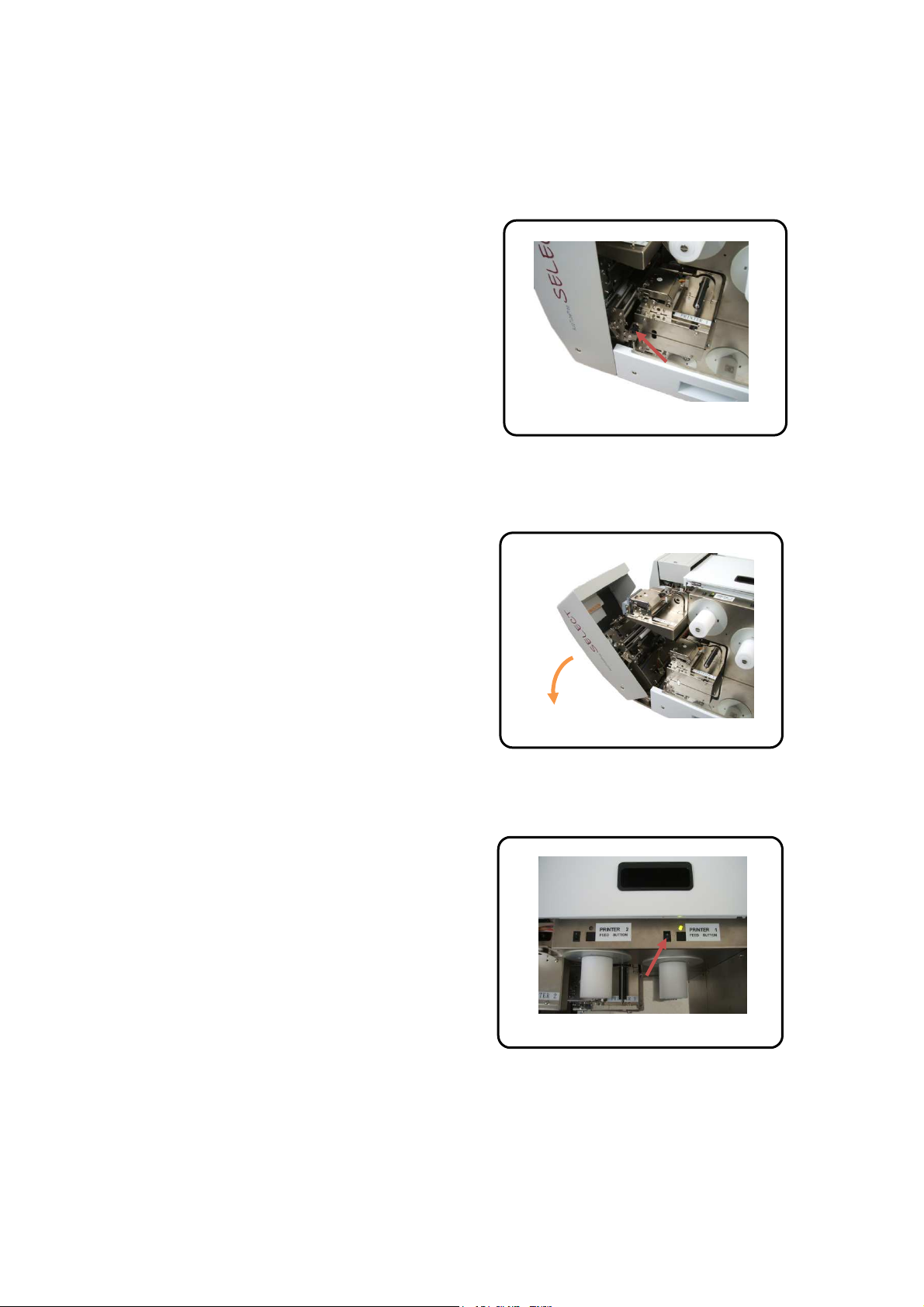
(1)Printer 1 (Main Printer)
Open and fold Label Maintenance Cover.
Release the Cover Lock as shown.
(2)Open Front Cover, Right as shown.
(3)Turn on On/Off switch of Printer 1
(Main Printer).
Fig. 2-007
Fig. 2-006
Fig. 2-008

1-3. How To Set Label Roll
3-5
(4)Prepare the label roll by peeling off labels
in approx 12 cm or 5” long from the roll’s
leading edge as shown.
(5)Place the prepared label roll to the Roll
Holder A 6-③, and be sure the leading
edge is placed above the Liner Paper
Winder 6-⑦as shown.
(6)This is the Head Open Lever of the
Printer 1 (Main Printer).
Fig. 2-009
Fig. 2-010 6-③
6-⑦
Fig. 2-011

1-3. How To Set Label Roll
3-6
(7)Push the Head Open Lever and open the
head as shown.
(8)Insert the leading edge and adjust the
guide as shown.
(9)Lead the leading edge to the Liner Paper
Winder as shown.
Fig. 2-012
Fig. 2-014
Fig. 2-013

1-3. How To Set Label Roll
3-7
(10)Remove the cramp from Liner Paper
Winder as shown.
(11)Wind the leading edge manually and
hold by the cramp as shown.
(12)Close the head as shown.
Fig. 2-017
Fig. 2-015
Fig. 2-016

1-3. How To Set Label Roll
3-8
(13)Feed the label by pressing the feed key
as shown.
The printer automatically stops when the
first label comes to the print position.
(14)The label setting for the Printer 1 (Main
Printer) has been completed.
(15)Printer 2 (Secondary Printer)
Turn on On/Off switch of Printer 2
(Secondary Printer).
Fig. 2-019
Fig. 2-018
Fig. 2-020

1-3. How To Set Label Roll
3-9
(16)Place the prepared label roll to the Roll
Holder B 6-④.
(17)Open the head and insert the leading
edge until the edge comes out from the auto
cutter unit, and adjust the guide as shown.
(18)Close the head as shown.
Fig. 2-021
6
-
④
Fig. 2-023
Fig. 2-022

1-3. How To Set Label Roll
3-10
(19)Close the Front Cover, Right as shown
and be sure the cover is firmly locked.
(20)Feed the label by pressing the feed key
as shown.
The printer automatically stops when the
first label comes to the print position.
(21)The label setting for the Printer 2
(Secondary Printer) has been completed.
Fig. 2-026
Fig. 2-024
Fig. 2-025
Table of contents


