HiLook NVR-100MH-D/W Series User manual

Network Video Recorder
Quick Start Guide

Legal Information
All Rights Reserved
Any and all information, including, among others, wordings, pictures, graphs are the properties of
Hangzhou Hikvision Digital Technology Co., Ltd. or its subsidiaries (hereinafter referred to be
"Hikvision"). This user manual (hereinafter referred to be "the Manual") cannot be reproduced,
changed, translated, or distributed, partially or wholly, by any means, without the prior written
permission of Hikvision. Unless otherwise stipulated, Hikvision does not make any warranties,
guarantees or representations, express or implied, regarding to the Manual.
About this Manual
Pictures, charts, images and all other information hereinafter are for description and explanation
only. The information contained in the Manual is subject to change, without notice, due to
firmware updates or other reasons. Please find the latest version in the company website
(http://overseas.hikvision.com/en/). Please use this user manual under the guidance of
professionals.
Trademarks
and other Hikvision's trademarks and logos are the properties of Hikvision in
various jurisdictions. Other trademarks and logos mentioned below are the properties of their
respective owners.
: The terms HDMI and HDMI High-Definition Multimedia Interface, and the HDMI
Logo are trademarks or registered trademarks of HDMI Licensing Administrator, Inc. in the United
States and other countries.
Disclaimer
TO THE MAXIMUM EXTENT PERMITTED BY APPLICABLE LAW, THE PRODUCT DESCRIBED, WITH ITS
HARDWARE, SOFTWARE AND FIRMWARE, IS PROVIDED "AS IS", WITH ALL FAULTS AND ERRORS, AND
HIKVISION MAKES NO WARRANTIES, EXPRESS OR IMPLIED, INCLUDING WITHOUT LIMITATION,
MERCHANTABILITY, SATISFACTORY QUALITY, FITNESS FOR A PARTICULAR PURPOSE, AND NON-
INFRINGEMENT OF THIRD PARTY. IN NO EVENT WILL HIKVISION, ITS DIRECTORS, OFFICERS, EMPLOYEES, OR
AGENTS BE LIABLE TO YOU FOR ANY SPECIAL, CONSEQUENTIAL, INCIDENTAL, OR INDIRECT DAMAGES,
INCLUDING, AMONG OTHERS, DAMAGES FOR LOSS OF BUSINESS PROFITS, BUSINESS INTERRUPTION, OR
LOSS OF DATA OR DOCUMENTATION, IN CONNECTION WITH THE USE OF THIS PRODUCT, EVEN IF
HIKVISION HAS BEEN ADVISED OF THE POSSIBILITY OF SUCH DAMAGES.
REGARDING TO THE PRODUCT WITH INTERNET ACCESS, THE USE OF PRODUCT SHALL BE WHOLLY AT YOUR
OWN RISKS. HIKVISION SHALL NOT TAKE ANY RESPONSIBILITIES FOR ABNORMAL OPERATION, PRIVACY
LEAKAGE OR OTHER DAMAGES RESULTING FROM CYBER ATTACK, HACKER ATTACK, VIRUS INSPECTION, OR
OTHER INTERNET SECURITY RISKS; HOWEVER, HIKVISION WILL PROVIDE TIMELY TECHNICAL SUPPORT IF
REQUIRED.
SURVEILLANCE LAWS VARY BY JURISDICTION. PLEASE CHECK ALL RELEVANT LAWS IN YOUR JURISDICTION
BEFORE USING THIS PRODUCT IN ORDER TO ENSURE THAT YOUR USE CONFORMS THE APPLICABLE LAW.
HIKVISION SHALL NOT BE LIABLE IN THE EVENT THAT THIS PRODUCT IS USED WITH ILLEGITIMATE
PURPOSES. IN THE EVENT OF ANY CONFLICTS BETWEEN THIS MANUAL AND THE APPLICABLE LAW, THE
LATER PREVAILS.

Regulatory Information
FCC Information
Please take attention that changes or modification not expressly approved by the party responsible for
compliance could void the user’s authority to operate the equipment.
FCC compliance: This product has been tested and found to comply with the limits for a Class B digital
device, pursuant to Part 15 of the FCC Rules. These limits are designed to provide reasonable protection
against harmful interference in a residential installation. This product generates, uses, and can radiate radio
frequency energy and, if not installed and used in accordance with the instructions, may cause harmful
interference to radio communications. However, there is no guarantee that interference will not occur in a
particular installation. If this product does cause harmful interference to radio or television reception,
which can be determined by turning the equipment off and on, the user is encouraged to try to correct the
interference by one or more of the following measures:
1. Reorient or relocate the receiving antenna.
2. Increase the separation between the equipment and receiver.
3. Connect the equipment into an outlet on a circuit different from that to which the receiver is connected.
4. Consult the dealer or an experienced radio/TV technician for help.
FCC Conditions
This device complies with part 15 of the FCC Rules. Operation is subject to the following two conditions:
1. This device may not cause harmful interference.
2. This device must accept any interference received, including interference that may cause undesired
operation.
EU Conformity Statement
This product and - if applicable - the supplied accessories too are marked with "CE" and comply
therefore with the applicable harmonized European standards listed under the EMC Directive
2014/30/EU, the LVD Directive 2014/35/EU, the RoHS Directive 2011/65/EU.
2012/19/EU (WEEE directive): Products marked with this symbol cannot be disposed of as
unsorted municipal waste in the European Union. For proper recycling, return this product to
your local supplier upon the purchase of equivalent new equipment, or dispose of it at
designated collection points. For more information see: www.recyclethis.info
2006/66/EC (battery directive): This product contains a battery that cannot be disposed of as
unsorted municipal waste in the European Union. See the product documentation for specific
battery information. The battery is marked with this symbol, which may include lettering to
indicate cadmium (Cd), lead (Pb), or mercury (Hg). For proper recycling, return the battery to your supplier
or to a designated collection point. For more information see: www.recyclethis.info
Industry Canada ICES-003 Compliance

This device meets the CAN ICES-3 (B)/NMB-3(B) standards requirements.
This device complies with Industry Canada licence-exempt RSS standard(s). Operation is subject to the
following two conditions:
(1) this device may not cause interference, and
(2) this device must accept any interference, including interference that may cause undesired
operation of the device.
Le présent appareil est conforme aux CNR d'Industrie Canada applicables aux appareils
radioexempts de licence. L'exploitation est autorisée aux deux conditions suivantes :
(1) l'appareil ne doit pas produire de brouillage, et
(2) l'utilisateur de l'appareil doit accepter tout brouillage radioélectrique subi, même si le
brouillage est susceptible d'en compromettre le fonctionnement.
Under Industry Canada regulations, this radio transmitter may only operate using an antenna of a
type and maximum (or lesser) gain approved for the transmitter by Industry Canada. To reduce
potential radio interference to other users, the antenna type and its gain should be so chosen that
the equivalent isotropically radiated power (e.i.r.p.) is not more than that necessary for successful
communication.
Conformément à la réglementation d'Industrie Canada, le présent émetteur radio peut
fonctionner avec une antenne d'un type et d'un gain maximal (ou inférieur) approuvé pour
l'émetteur par Industrie Canada. Dans le but de réduire les risques de brouillage radioélectrique à
l'intention des autres utilisateurs, il faut choisir le type d'antenne et son gain de sorte que la
puissance isotrope rayonnée équivalente (p.i.r.e.) ne dépasse pas l'intensité nécessaire à
l'établissement d'une communication satisfaisante.
This equipment should be installed and operated with a minimum distance 20cm between the
radiator and your body.
Cet équipement doit être installé et utilisé à une distance minimale de 20 cm entre le radiateur et votre
corps.

Applicable Model
This manual is applicable to the following models.
Table 1-1 Applicable Model
Series
Model
NVR-100MH-D/W
NVR-104MH-D/W
NVR-108MH-D/W
NVR-100MH-D/W(C)
NVR-104MH-D/W(C)
NVR-108MH-D/W(C)
Symbol Conventions
The symbols that may be found in this document are defined as follows.
Symbol
Description
Danger
Indicates a hazardous situation which, if not avoided, will or could
result in death or serious injury.
Caution
Indicates a potentially hazardous situation which, if not avoided,
could result in equipment damage, data loss, performance
degradation, or unexpected results.
Note
Provides additional information to emphasize or supplement
important points of the main text.

Safety Instruction
●Proper configuration of all passwords and other security settings is the responsibility of the
installer and/or user.
●In the use of the product, you must be in strict compliance with the electrical safety regulations
of the nation and region. Please refer to technical specifications for detailed information.
●Input voltage should meet both the SELV (Safety Extra Low Voltage) and the Limited Power
Source with 100 VAC to 240 VAC or 12 VDC according to the IEC60950-1 standard. Please refer
to technical specifications for detailed information.
●Do not connect several devices to one power adapter as adapter overload may cause over-
heating or a fire hazard.
●Please make sure that the plug is firmly connected to the power socket.
●If smoke, odor or noise rises from the device, turn off the power at once and unplug the power
cable, and then please contact the service center.
Preventive and Cautionary Tips
Before connecting and operating your device, please be advised of the following tips:
●Ensure recorder is installed in a well-ventilated, dust-free environment.
●Recorder is designed for indoor use only.
●Keep all liquids away from the device.
●Ensure environmental conditions meet factory specifications.
●Ensure recorder is properly secured to a rack or shelf. Major shocks or jolts to the recorder as a
result of dropping it may cause damage to the sensitive electronics within the recorder.
●Use the device in conjunction with an UPS if possible.
●Power down the recorder before connecting and disconnecting accessories and peripherals.
●A factory recommended HDD should be used for this device.
●Improper use or replacement of the battery may result in hazard of explosion. Replace with the
same or equivalent type only. Dispose of used batteries according to the instructions provided
by the battery manufacturer.
●When installing the device into a cabinet over 2U height, it is suggested to use rack shelf to bear
the weight. If the cabinet height is over 4U, it is suggested to use slide rails or rack shelf to bear
the weight.

TABLE OF CONTENTS
Chapter 1 Rear Panel Interfaces Description ...............................................................................8
Chapter 2 Installation and Connections ......................................................................................9
2.1 Device Installation.................................................................................................................9
2.2 HDD Installation ....................................................................................................................9
2.2.1 Fix-on-Bottom Installation.........................................................................................9
Chapter 3 Menu Operation.......................................................................................................11
3.1 Startup, Shutdown and Reboot ..........................................................................................11
3.2 Activate Your Device ...........................................................................................................11
3.3 Set Unlock Pattern...............................................................................................................12
3.4 User Login ............................................................................................................................13
3.5 Network Settings.................................................................................................................14
3.5.1 Configure General Settings ......................................................................................14
3.5.2 Configure Wi-Fi.........................................................................................................14
3.5.3 Configure HiLookVision............................................................................................16
3.6 Add Network Cameras ........................................................................................................17
3.6.1 Add Wi-Fi Cameras ...................................................................................................17
3.6.2 Add IP Cameras ........................................................................................................17
3.7 Live View..............................................................................................................................18
3.8 Playback...............................................................................................................................18
3.9 Access via Web Browser .....................................................................................................19

Chapter 1 Rear Panel Interfaces Description
The rear panel interfaces vary with different models. Refer to the following table for common
interfaces description.
Table 1-1 Common Interfaces Description of Rear Panel
Item
Description
Item
Description
AUDIO IN
RCA connector for audio
input.
AUDIO OUT
RCA connector for audio
output.
LINE IN
RCA connector for two-way
audio input.
USB
Universal Serial Bus (USB)
interface for additional device.
VGA
DB15 connector for local
video output and menu
display.
HDMI
HDMI interface for video
output.
RS-485
RS-485 serial interface for
pan/tilt unit, speed dome, etc.
RS-232
RS-232 interface for
parameter configuration, or
transparent channel.
LAN
RJ-45 self-adaptive Ethernet
interface.
eSATA
Storage and expansion
interface for record or backup.
ALARM
IN/OUT
Alarm input/output interface.
GND
Ground.
Power Switch
Switch for turning on/off the
device.
Power Supply
100 to 240 VAC, 48 VDC, or 12
VDC power supply, different
models vary.
Wi-Fi antenna interface.

Chapter 2 Installation and Connections
2.1 Device Installation
During the device installation:
●Use brackets for rack mounting.
●Ensure ample room for audio and video cables.
●When routing cables, ensure the bend radius of the cables are no less than five times of its
diameter.
●Allow at least 2 cm (≈0.75 inch) of space among racks mounted devices.
●Ensure the device is grounded.
●Environmental temperature should be within the range of -10 °C to 55 °C (14 °F to 131 °F).
●Environmental humidity should be within the range of 10% to 90%.
2.2 HDD Installation
Disconnect the power from the device before installing a hard disk drive (HDD). A factory
recommended HDD should be used for this installation.
Tools Required: Screwdriver.
2.2.1 Fix-on-Bottom Installation
Fix-on-bottom installation is applicable when you need to install and fix the HDD on the device
bottom.
Steps
1. Remove the cover from device by unfastening the screws on panels.
Figure 2-1 Remove Cover
2. Connect the data cable and power cable.
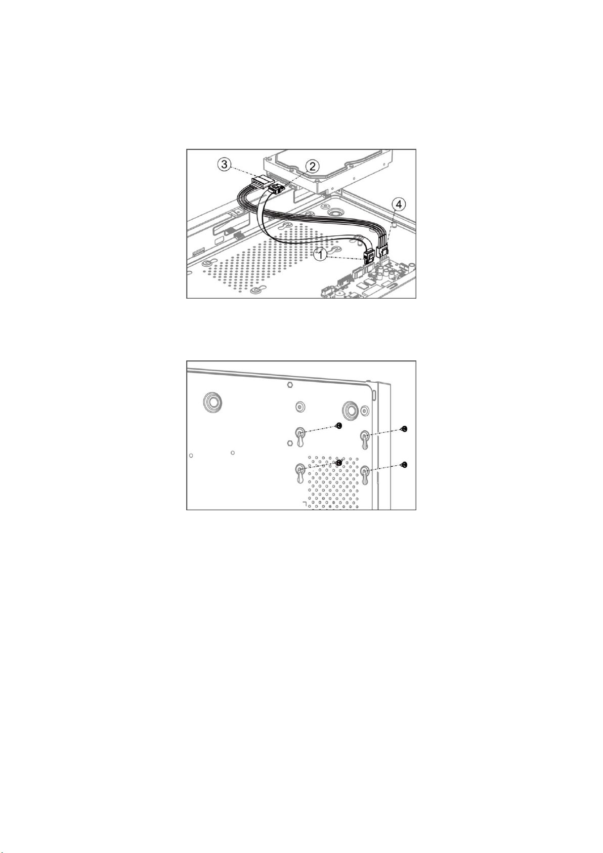
1) Connect one end of data cable to the device motherboard.
2) Connect the other end of data cable to HDD.
3) Connect one end of power cable to HDD.
4) Connect the other end of power cable to the device motherboard.
Figure 2-2 Connect Cables
3. Set the device up, match HDD screw threads with the reserved holes on the device bottom, and
fix HDD with screws.
Figure 2-3 Fix HDD to Device Bottom
4. Optional: Repeat the steps above to install other HDDs.
5. Reinstall the device cover and fasten screws.

Chapter 3 Menu Operation
3.1 Startup, Shutdown and Reboot
Proper startup and shutdown procedures are crucial to expand the life of your device.
Startup Your Device
Ensure the voltage of the extra power supply satisfies the requirement, and the ground
connection is working properly.
Plug the power supply into an electrical outlet. It is HIGHLY recommended that an Uninterruptible
Power Supply (UPS) is used in conjunction with the device.
Press the power button on the panel. The power indicator LED would be lighted up which
indicating the device begins to start up.
Shut Down Your Device
Go to Menu → Shutdown. Click Shutdown, and click Yes.
If your device has a power button on the front panel, you can also hold the power button for 3
seconds, and then enter the admin user name and password to shut down your device.
Note
Do not press the POWER button again when the system is shutting down.
Reboot Your Device
Go to Menu → Shutdown. Click Reboot, and your device will restart.
Figure 3-1 Startup, Shutdown and Reboot
3.2 Activate Your Device
For the first-time access, you need to activate the device by setting an admin password. No
operation is allowed before activation. You can also activate the device via Web Browser, SADP or
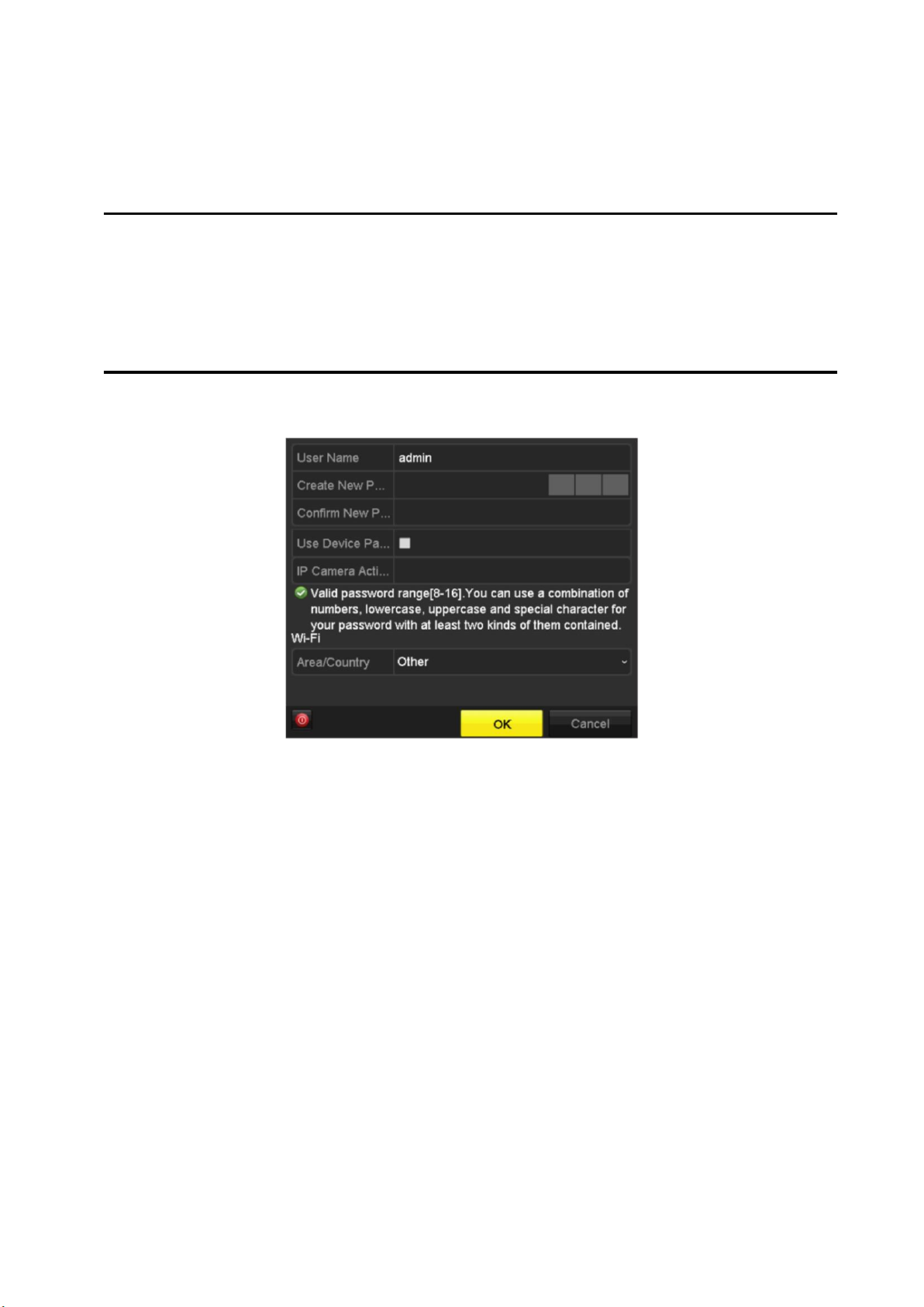
Client Software.
Steps
1. Enter the password in Create New Password and Confirm New Password.
Warning
We highly recommend you create a strong password of your own choosing (Using a minimum of
8 characters, including at least three of the following categories: upper case letters, lower case
letters, numbers, and special characters.) in order to increase the security of your product. And
we recommend you reset your password regularly, especially in the high security system,
resetting the password monthly or weekly can better protect your product.
Figure 3-2 Set Admin Password
2. Check Use Device Password to Active IP Camera, or enter the password in IP Camera
Activation to activate the IP camera(s) connected to the device.
3. Set Area/Country.
4. Click OK.
What to do next
Export the GUID file to the USB flash driver for the future password resetting.
3.3 Set Unlock Pattern
For the admin user, you can set the unlock pattern for device login after it is activated.
Steps
1. Use mouse to draw a pattern among the 9 dots on the screen. Release the mouse when the
pattern is done.
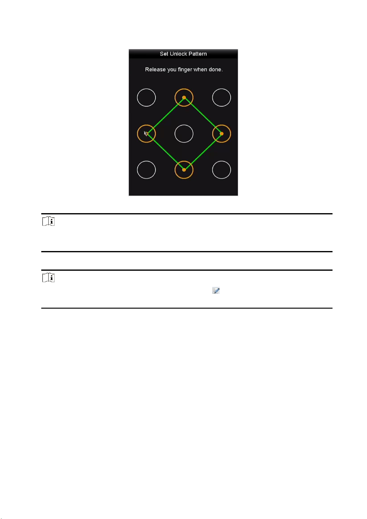
Figure 3-3 Set Unlock Pattern
Note
●The pattern shall have 4 dots at least.
●Each dot can be connected for once only.
2. Draw the same pattern again to confirm it.
Note
You can go to Menu → Configuration → User, and click to edit or disable the unlock
pattern.
3.4 User Login
You have to log in to the device before operating the menu and other functions.
Steps
1. Select a user account.
2. Enter the password for the selected user.
3. Click Login.

Figure 3-4 Login
●For the admin, if you have entered the wrong password for 7 times, the account will be
locked for 60 seconds.
●For the operator, if you have entered the wrong password for 5 times, the account will be
locked for 60 seconds.
3.5 Network Settings
3.5.1 Configure General Settings
You shall properly configure the network settings before operating the device over network.
Steps
1. Go to Menu → Configuration → Network → General.
Figure 3-5 Network Settings
2. Set the general network parameters.
3. Click Apply.
3.5.2 Configure Wi-Fi
The device can work as a wireless network router. Follow the steps to setup a network router.
Steps
1. Go to Menu → Configuration → WIFI.

Figure 3-6 Wi-Fi Settings
2. Configure wireless network parameters, including Network Bridging, SSID, Security Mode, and
Key.
Network Bridging
Enable device to create a single aggregate network from multiple communication networks
or network segments.
SSID
It is the short for Service Set Identifier. SSID is the Wi-Fi name that the device provides.
Area/Country
Select where the router is used.
Channel
Select the best channel according to your situation.
Security Mode
Select the security protocol for the wireless network.
Encryption Type
It is used to protect information. TKIP and AES are selectable.
Key
Enter the encryption key.
WPS
It is the short of Wi-Fi Protected Setup. Click the button and then you can connect the
wireless network without password for once.
3. Click Apply to save the settings.

3.5.3 Configure HiLookVision
HiLookVision provides mobile phone application and platform service to access and manage your
connected devices, which enables you to get a convenient remote access to the surveillance
system.
Steps
1. Go to Menu → Configuration → Network → Platform Access.
2. Check Enable. The service terms will pop up.
1) Enter the verification code in Verification Code.
2) Scan the QR code to read the service terms and privacy statement.
3) Check The HiLookVision service will require internet access. Please read Service Terms and
Privacy Statement before enabling the service if you agree with the service terms and
privacy statement.
4) Click OK to save the settings.
Note
●HiLookVision is disabled by default.
●The verification code is empty by default. It must contain 6 to 12 letters or numbers, and it is
case sensitive.
3. Optional: Configure following parameters.
●Check Custom and enter Server Address as your desire.
●Check Enable Stream Encryption, then verification code is required for remote access and
live view.
4. Bind your device with a HiLookVision account.
1) Use a smart phone to scan the QR code, and download HiLookVision app. You can also
download it from https://appstore.hikvision.com, or the QR code below. Refer to
HiLookVision Mobile Client User Manual for details.
Figure 1-16 Download HiLookVision
2) Use HiLookVision to scan the device QR, and bind the device.

Note
If the device is already bound with an account, you can click Unbind to unbind with the
current account.
5. Click Apply.
What to do next
After configuration, you can access and manage your devices through HiLookVision app or
website.
3.6 Add Network Cameras
Before you can get live video or record the video files, you shall add network cameras to the
device.
3.6.1 Add Wi-Fi Cameras
You can use Wi-Fi match function to search Wi-Fi cameras that are not activated, and add them to
the device automatically.
Select Wi-Fi Match from the right-click menu in live view mode, and the device will search and add
Wi-Fi cameras. The process will take about 2 minutes. The Wi-Fi camera will use IP Camera
Activation Password as its password. (Refer to Activate Your Device.)
Note
●It is recommended to keep the distance between Wi-Fi camera and device within 50 meters.
●Only certain Wi-Fi camera models and versions support this function.
●Ensure the Wi-Fi camera is powered on, not activated, and has not been connected with other
devices via network cable.
3.6.2 Add IP Cameras
Ensure the network connection is valid and correct, and the IP camera has been activated.
Before You Start
Ensure the network connection is valid and correct, and the IP camera has been activated.
Enter the context of your task here (optional).
Steps
1. Click to select an idle window in the live view mode.
2. Click in the center of the window.

Figure 3-7 Add IP Camera
3. Select the detected IP camera directly, or enter IP camera parameters.
4. Click Add.
3.7 Live View
Live view shows you the video image getting from each camera in real time. The device will
automatically enter Live View mode when powered on. You can click at the toolbar to start
recording.
In the live view mode, there are icons at the right top of the screen to indicate the status of record
and alarm for each channel.
Table 3-1 Description of Live View Icons
Item
Description
Item
Description
Alarm (video loss, tampering,
motion detection, VCA or
sensor alarm).
Alarm and Record.
Record (manual record,
continuous record, motion
detection, VCA or alarm
triggered record).
Event/Exception (event and
exception information,
appears at the lower-left
corner of the screen).
3.8 Playback
The recorded video files and pictures on HDD can be played back. Refer to the user manual for
details of each playback mode.
Steps
1. Go to Menu → Playback.
2. Select the channel(s) in the channel list for playback.
3. Double click a date on the calendar.
4. Optional: Use the toolbar at the bottom to control the playing progress.

5. Optional: Select the channel(s) to execute simultaneous playback of multiple channels.
Figure 3-8 Playback
3.9 Access via Web Browser
You can get access to the device via web browser. The following web browsers are supported:
Internet Explorer 6.0, Internet Explorer 7.0, Internet Explorer 8.0, Internet Explorer 9.0, Internet
Explorer 10.0, Apple Safari, Mozilla Firefox, and Google Chrome. The supported resolutions include
1024*768 and above. The use of the product with Internet access might be under network security
risks. For avoidance of any network attacks and information leakage, please strengthen your own
protection. If the product does not work properly, please contact with your dealer or the nearest
service center.
Steps
1. Open web browser, enter the IP address of the device, and press Enter.
2. Log in to the device.
–If the device has not been activated, activate the device first by setting the password for the
admin user account.
–If the device is already activated, enter the user name and password to log in.
3. Follow the installation prompts to install the plug-in before viewing the live video and managing
the device.
Note
●You may have to close the web browser to finish the installation of the plug-in.
●After login, you can perform the operation and configuration of the device, including the live
view, playback, log search, configuration, etc.

UD19791B
HiLookVision for Users
This manual suits for next models
6
Table of contents
Other HiLook Network Hardware manuals


