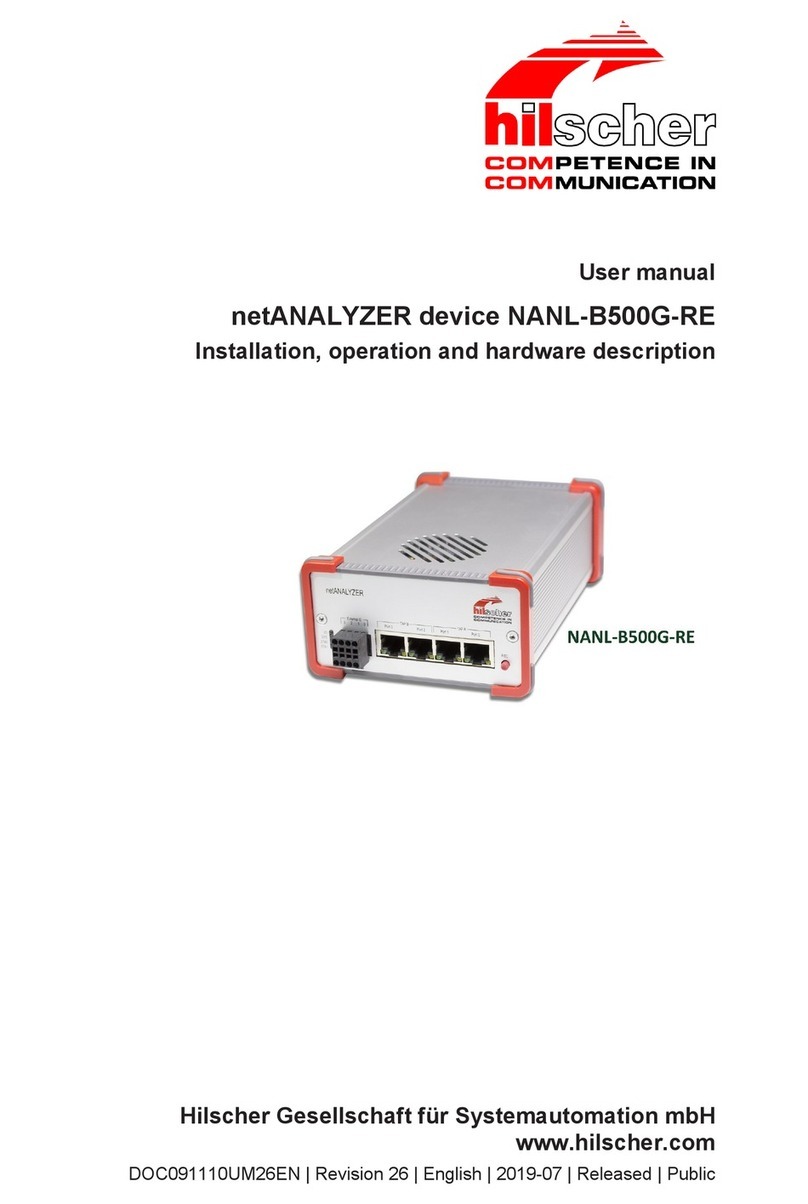
hilscher NANL-B500G-RE User manual

User manual
netANALYZER devices
Installation, operation and hardware description
Hilscher Gesellschaft für Systemautomation mbH
www.hilscher.com
DOC091110UM18EN | Revision 18 | English | 2016-12 | Released | Public

Table of contents 2/80
Table of contents
1 Introduction .............................................................................................................................. 5
1.1 About the user manual .....................................................................................................5
1.1.1 List of revisions ................................................................................................. 5
1.1.2 Hardware, firmware and driver versions ........................................................... 6
1.1.3 Conventions in this manual............................................................................... 7
1.2 Installation DVD and documentation................................................................................8
1.3 Legal notes.......................................................................................................................9
1.3.1 Copyright........................................................................................................... 9
1.3.2 Important notes ................................................................................................. 9
1.3.3 Exclusion of liability......................................................................................... 10
1.3.4 Warranty ......................................................................................................... 10
1.3.5 Export regulations ........................................................................................... 11
1.3.6 Registered trademarks.................................................................................... 11
1.3.7 Licenses.......................................................................................................... 11
1.3.8 Obligation to read and understand the manual............................................... 11
2 Safety ...................................................................................................................................... 12
2.1 General note ..................................................................................................................12
2.2 Intended use ..................................................................................................................12
2.3 Personnel qualification ...................................................................................................12
2.4 Safety instructions to avoid personal injury....................................................................13
2.4.1 Electrical shock hazard (NANL-C500-RE) ...................................................... 13
2.5 Safety instructions to avoid property damage ................................................................14
2.5.1 Device destruction by exceeding allowed supply voltage ............................... 14
2.5.2 Device destruction by exceeding allowed signaling voltage ........................... 14
2.5.3 Device destruction by exceeding allowed external IO interface output current ...
15
2.5.4 Damage of externally attached hardware ....................................................... 15
2.5.5 Electrostatically sensitive devices (NANL-C500-RE)...................................... 16
2.5.6 Assignment of wrong IP addresses, malfunction (NANL-B500G-RE) ............ 16
2.6 References safety ..........................................................................................................16
2.7 Labeling of safety messages..........................................................................................17
3 Description ............................................................................................................................. 18
3.1 Recording and analyzing data traffic..............................................................................19
3.2 Interactive and Autonomous operating mode ................................................................21
4 System requirements ............................................................................................................ 22
4.1 Hardware requirements..................................................................................................22
4.2 Power supply and host interface ....................................................................................23
4.3 Maximum permissible output current (external IO interface) .........................................24
4.4 Requirements NANL-B500G-RE (Autonomous operating mode) ..................................25
5 Getting started ....................................................................................................................... 26
5.1 Notes for installation and operation................................................................................26
5.2 Overview installation ......................................................................................................27
5.3 Overview installation update ..........................................................................................28
5.4 Configuring the NANL-B500G-RE IP address ..............................................................29
netANALYZER devices | Installation, operation and hardware description
DOC091110UM18EN | Revision 18 | English | 2016-12 | Released | Public
© Hilscher 2007-2016

Table of contents 3/80
5.5 Autonomous operating mode for NANL-B500G-RE.......................................................31
5.5.1 Set the time for the autonomous operating mode........................................... 33
5.5.2 Displaying lost frames in Wireshark................................................................ 35
6 Device drawings..................................................................................................................... 37
6.1 Analyzer card NANL-C500-RE.......................................................................................37
6.2 Analyzer device NANL-B500G-RE.................................................................................38
7 Hardware installation and operation.................................................................................... 39
7.1 Safety messages on personal injury ..............................................................................39
7.1.1 Electrical shock hazard (NANL-C500-RE) ...................................................... 39
7.2 Property damage messages ..........................................................................................40
7.2.1 Device destruction by exceeding allowed supply voltage ............................... 40
7.2.2 Device destruction by exceeding allowed signaling voltage ........................... 40
7.2.3 Device destruction by exceeding permissible external IO interface output
current............................................................................................................. 41
7.2.4 Damage of externally attached hardware ....................................................... 41
7.2.5 Electrostatically sensitive devices (NANL-C500-RE)...................................... 42
7.2.6 Assignment of wrong IP addresses, malfunction (NANL-B500G-RE) ............ 42
7.3 Mounting analyzer card NANL-C500-RE to the PC .......................................................43
7.4 Connecting analyzer device NANL-B500G-RE to the PC (interactive opeating mode) ......
44
7.5 Connecting analyzer device NANL-B500G-RE to USB (Autonomous operating mode).....
45
7.6 Inserting netANALYZER hardware into the communication link ....................................47
7.6.1 Application case 1........................................................................................... 48
7.6.2 Application case 2........................................................................................... 49
7.6.3 Application case 3........................................................................................... 50
7.6.4 Application case 4........................................................................................... 51
7.7 Auto-crossover and port-switching.................................................................................53
7.8 How to update the NANL-B500G-RE firmware ..............................................................54
7.9 Temperature control of the fan (NANL- B500G-RE) ......................................................56
7.10 Demounting Analyzer Card NANL-C500-RE .................................................................57
8 Hardware properties .............................................................................................................. 58
8.1 Timestamp .....................................................................................................................59
8.2 Transparent Mode..........................................................................................................60
9 Troubleshooting..................................................................................................................... 61
10 LEDs........................................................................................................................................ 62
10.1 LEDs NANL-C500-RE....................................................................................................62
10.2 LEDs NANL-B500G-RE .................................................................................................63
10.2.1 SYS, STA0, STA1, I/O, LINK and RX (Front side).......................................... 63
10.2.2 LINK-ACT and LINK-1000/LINK100 (reverse side) ........................................ 65
11 Connections and interfaces.................................................................................................. 66
11.1 Power Supply NANL-B500G-RE....................................................................................66
11.2 Ethernet interface...........................................................................................................67
11.2.1 Ethernet pinning at the RJ45 socket ............................................................... 67
11.2.2 Data of the Ethernet connection ..................................................................... 67
netANALYZER devices | Installation, operation and hardware description
DOC091110UM18EN | Revision 18 | English | 2016-12 | Released | Public
© Hilscher 2007-2016

Table of contents 4/80
11.3 External IO interface ......................................................................................................68
11.3.1 Connection cable for external IO interface...................................................... 68
12 Technical data ........................................................................................................................ 69
12.1 Analyzer card NANL-C500-RE.......................................................................................69
12.2 Analyzer device NANL-B500G-RE.................................................................................71
13 Annex ...................................................................................................................................... 73
13.1 Hardware update for NXANL 500-RE Rev 2 and Rev 3 ................................................73
13.2 Failure in 10 MBit/s half duplex mode and workaround .................................................75
13.3 Disposal of waste electronic equipment.........................................................................76
Glossary.................................................................................................................................. 79
Contacts.................................................................................................................................. 80
netANALYZER devices | Installation, operation and hardware description
DOC091110UM18EN | Revision 18 | English | 2016-12 | Released | Public
© Hilscher 2007-2016

Introduction 5/80
1 Introduction
1.1 About the user manual
This user manual contains descriptions about the installation and the
operation of the netANALYZER hardware for the devices:
netANALYZER PC card with PCI Interface for real-time Ethernet and all
100BASE-T Ethernet networks
- NANL-C500-RE and
netANALYZER portable device with Gigabit Ethernet PC interface for
real-time Ethernet and all 10/100BASE-T Ethernet networks - NANL-
B500G-RE (Stand-alone Device).
1.1.1 List of revisions
Index Date Chapter Revisions
15 2015-02-05 All Any descripions about the software removed.
16 15-12-15 7.9 Section Temperature control of the fan (NANL- B500G-RE) [}page56] added.
17 2016-11-04 All,
all
1.1.2,
1.3.7,
Autonomous operating mode for NANL-B500G-RE added.
netANALYZER portable device with ExpressCard NANL-B500E-RE removed,
section Hardware, firmware and driver versions [}page6]updated.
Section Licenses [}page11] added.
3.1, 3.2, Section Recording and analyzing data traffic [}page19] completed, section
Interactive and Autonomous operating mode [}page21] added.
4.4, Section Requirements NANL-B500G-RE (Autonomous operating
mode) [}page25] added.
5.5, Section Autonomous operating mode for NANL-B500G-RE [}page31] added.
6.3, Section Analyzer device NANL-B500G-RE [}page38] added.
7.6, Section Connecting analyzer device NANL-B500G-RE to USB (Autonomous
operating mode) [}page45] added.
10.2.1, Section SYS, STA0, STA1, I/O, LINK and RX (Front side) [}page63] completed.
12.3 Section Analyzer device NANL-B500G-RE [}page71] added.
18 2016-12-02 All Corrections and notes added, especially on the autonomous operating mode for
NANL-B500G-RE.
10.2.1 Section SYS, STA0, STA1, I/O, LINK and RX (Front side) [}page63] revised.
Table1: List of revisions
For the descriptions about the software installation and operation
see the user manual Software installation for netANALYZER and
netANALYZER Scope, Installation and Operation for Windows
7/8 V2.0.xx on the installation DVD.
netANALYZER devices | Installation, operation and hardware description
DOC091110UM18EN | Revision 18 | English | 2016-12 | Released | Public
© Hilscher 2007-2016

Introduction 6/80
1.1.2 Hardware, firmware and driver versions
Device name Device type Part no. Revisio
n
netANALYZER PC card with PCI interface for real-time Ethernet and all
100BASE-T Ethernet networks
* Note: If you have already installed the netANALYZER card of the hardware
revision 2 or 3 in your PC, you must apply the netANALYZER hardware
update and then update the driver and the software.
NXANL 500-RE 7.310.100 2*
NXANL 500-RE 7.310.100 3*
NANL-C500-RE 7.310.100 4
netANALYZER portable Device with Gigabit Ethernet PC Interface for Real-
Time Ethernet and all 10/100BASE-T Ethernet Networks
NANL-B500G-RE 7.313.100 3
NANL-B500G-RE 7.313.100 4
Table2: netANALYZER hardware
Name File name Version Path
netANALYZER firmware NANL-500.nxf 1.6.x.x C:\Programme\
netANALYZER
Device Driver\...
netANALYZER / netSCOPE Device Driver NSCP-100.nxf 1.6.x.x
netANALYZER toolkit
NANL-B500G-RE image version <no data name> 1.2.0.0 <no path>
Table3: Installed netANALYZER files (firmware, driver, toolkit)
netANALYZER devices | Installation, operation and hardware description
DOC091110UM18EN | Revision 18 | English | 2016-12 | Released | Public
© Hilscher 2007-2016

Introduction 7/80
1.1.3 Conventions in this manual
Notes, instructions and results of operating steps are marked as follows:
Notes
Important:
<important note you must follow to avoid malfunction>
Note:
<general note>
<note where to find further information>
Instructions
1. Operation purpose
2. Operation purpose
ØInstruction
Results
Intermediate result
Final result
Safety messages
The labeling of safety messages is explained in the chapter Safety.
netANALYZER devices | Installation, operation and hardware description
DOC091110UM18EN | Revision 18 | English | 2016-12 | Released | Public
© Hilscher 2007-2016

Introduction 8/80
1.2 Installation DVD and documentation
Name DVD
netANALYZER / netSCOPE Device Driver; for Windows® 7 bzw. Windows® 8 (32-Bit und
64-Bit), Windows® 10 (32-Bit und 64-Bit)
netANALYZER and
netANALYZER Scope
Remote Access client (only for analyzer device NANL-B500G-RE)
netANALYZER Scope
Ethernet Device Configuration Tool (only for NANL-B500G-RE)
Documentation and examples
netANALYZER hardware update (netANALYZER_hw_update.iso) netANALYZER
NANL-B500G-RE firmware update (nanl-b500g-re.update)
Table4: Important installation components on the DVD
Detailed information about the contents of the installation DVD and
about the documentation for netANALYZER, see user manual
Software installation for netANALYZER.
netANALYZER devices | Installation, operation and hardware description
DOC091110UM18EN | Revision 18 | English | 2016-12 | Released | Public
© Hilscher 2007-2016

Introduction 9/80
1.3 Legal notes
1.3.1 Copyright
© Hilscher 2007-2016, Hilscher Gesellschaft für Systemautomation mbH
All rights reserved.
The images, photographs and texts in the accompanying material (user
manual, accompanying texts, documentation, etc.) are protected by
German and international copyright law as well as international trade and
protection provisions. You are not authorized to duplicate these in whole or
in part using technical or mechanical methods (printing, photocopying or
other methods), to manipulate or transfer using electronic systems without
prior written consent. You are not permitted to make changes to copyright
notices, markings, trademarks or ownership declarations. The included
diagrams do not take the patent situation into account. The company
names and product descriptions included in this document may be
trademarks or brands of the respective owners and may be trademarked or
patented. Any form of further use requires the explicit consent of the
respective rights owner.
1.3.2 Important notes
The user manual, accompanying texts and the documentation were created
for the use of the products by qualified experts, however, errors cannot be
ruled out. For this reason, no guarantee can be made and neither juristic
responsibility for erroneous information nor any liability can be assumed.
Descriptions, accompanying texts and documentation included in the user
manual do not present a guarantee nor any information about proper use
as stipulated in the contract or a warranted feature. It cannot be ruled out
that the user manual, the accompanying texts and the documentation do
not correspond exactly to the described features, standards or other data of
the delivered product. No warranty or guarantee regarding the correctness
or accuracy of the information is assumed.
We reserve the right to change our products and their specification as well
as related user manuals, accompanying texts and documentation at all
times and without advance notice, without obligation to report the change.
Changes will be included in future manuals and do not constitute any
obligations. There is no entitlement to revisions of delivered documents.
The manual delivered with the product applies.
Hilscher Gesellschaft für Systemautomation mbH is not liable under any
circumstances for direct, indirect, incidental or follow-on damage or loss of
earnings resulting from the use of the information contained in this
publication.
netANALYZER devices | Installation, operation and hardware description
DOC091110UM18EN | Revision 18 | English | 2016-12 | Released | Public
© Hilscher 2007-2016

Introduction 10/80
1.3.3 Exclusion of liability
The software was produced and tested with utmost care by Hilscher
Gesellschaft für Systemautomation mbH and is made available as is. No
warranty can be assumed for the performance and flawlessness of the
software for all usage conditions and cases and for the results produced
when utilized by the user. Liability for any damages that may result from the
use of the hardware or software or related documents, is limited to cases of
intent or grossly negligent violation of significant contractual obligations.
Indemnity claims for the violation of significant contractual obligations are
limited to damages that are foreseeable and typical for this type of contract.
It is strictly prohibited to use the software in the following areas:
·for military purposes or in weapon systems;
·for the design, construction, maintenance or operation of nuclear
facilities;
·in air traffic control systems, air traffic or air traffic communication
systems;
·in life support systems;
·in systems in which failures in the software could lead to personal injury
or injuries leading to death.
We inform you that the software was not developed for use in dangerous
environments requiring fail-proof control mechanisms. Use of the software
in such an environment occurs at your own risk. No liability is assumed for
damages or losses due to unauthorized use.
1.3.4 Warranty
Although the hardware and software was developed with utmost care and
tested intensively, Hilscher Gesellschaft für Systemautomation mbH does
not guarantee its suitability for any purpose not confirmed in writing. It
cannot be guaranteed that the hardware and software will meet your
requirements, that the use of the software operates without interruption and
that the software is free of errors. No guarantee is made regarding
infringements, violations of patents, rights of ownership or the freedom from
interference by third parties. No additional guarantees or assurances are
made regarding marketability, freedom of defect of title, integration or
usability for certain purposes unless they are required in accordance with
the law and cannot be limited. Warranty claims are limited to the right to
claim rectification.
netANALYZER devices | Installation, operation and hardware description
DOC091110UM18EN | Revision 18 | English | 2016-12 | Released | Public
© Hilscher 2007-2016

Introduction 11/80
1.3.5 Export regulations
The delivered product (including the technical data) is subject to export or
import laws as well as the associated regulations of different counters, in
particular those of Germany and the USA. The software may not be
exported to countries where this is prohibited by the United States Export
Administration Act and its additional provisions. You are obligated to
comply with the regulations at your personal responsibility. We wish to
inform you that you may require permission from state authorities to export,
re-export or import the product.
1.3.6 Registered trademarks
Windows® 7, Windows® 8 and Windows® 10 are registered trade marks of
the Microsoft Corporation.
Wireshark® and the "fin" logo are a registered trademark of Gerald Combs.
Adobe-Acrobat® is a registered trademark of the Adobe Systems
Incorporated.
PCI™ is a trademark of the Peripheral Component Interconnect Special
Interest Group (PCI-SIG).
All other mentioned trademarks are property of their respective legal
owners.
1.3.7 Licenses
The analyzer device NANL-B500G-RE can be used both in the "Interactive
operating mode" with a connected PC as well as in the "Autonomous
operating mode" without a PC.
A license is required to use the "Autonomous operating mode".
Required license: 8582.060 LIC/NANL/SA
1.3.8 Obligation to read and understand the manual
Important:
To avoid personal injury and to avoid property damage to your
system or to your device, you must read and understand all
instructions in the manual and all accompanying texts to your PC
card, before installing and operating your device.
ØFirst read the Safety instructions in the Safety chapter.
ØObey to all Safety messages in the manual.
ØKeep the product DVD providing the product manuals.
netANALYZER devices | Installation, operation and hardware description
DOC091110UM18EN | Revision 18 | English | 2016-12 | Released | Public
© Hilscher 2007-2016

Safety 12/80
2 Safety
2.1 General note
The documentation in the form of a user manual, an operating instruction
manual or other manual types, as well as the accompanying texts have
been created for the use of the products by educated personnel. When
using the products, all Safety Messages, Integrated Safety Messages,
Property Damage Messages and all valid legal regulations must be obeyed.
Technical knowledge is presumed. The user has to assure that all legal
regulations are obeyed.
2.2 Intended use
The netANALYZER devices described in this user manual each work as a
passive Ethernet analyzer in RT-Ethernet systems. The analyzer card
NANL-C500-RE and the analyzer device NANL-B500G-RE analyze the
data in a communication link and capture the incoming Ethernet frames.
Device name Device type
netANALYZER PC card with PCI interface for real-time Ethernet and all 100BASE-T
Ethernet networks
NANL-C500-RE
netANALYZER portable device with Gigabit Ethernet PC interface for real-time Ethernet
and all 10/100BASE-T Ethernet networks
NANL-B500G-RE
Table5: netANALYZER devices
If the analyzer card NANL-C500-RE and the analyzer device NANL-B500G-
RE are used outside of the scope described in this user manual
respectively in the other netANALYZER documentations, an error free
function can not be guaranteed.
2.3 Personnel qualification
The analyzer card NANL-C500-RE and the analyzer device NANL-B500G-
RE must only be installed, configured and removed by qualified personnel.
Job-specific technical skills for people professionally working with electricity
must be present concerning the following topics:
·Safety and health at work
·Mounting and connecting of electrical equipment
·Measurement and Analysis of electrical functions and systems
·Evaluation of the safety of electrical systems and equipment
·Installing and Configuring IT systems
netANALYZER devices | Installation, operation and hardware description
DOC091110UM18EN | Revision 18 | English | 2016-12 | Released | Public
© Hilscher 2007-2016

Safety 13/80
2.4 Safety instructions to avoid personal injury
To ensure your own personal safety and to avoid personal injury, you
necessarily must read, understand and follow the following safety
instructions as well as all the other safety messages in this manual about
danger causing personal injury, before you install and operate your device.
2.4.1 Electrical shock hazard (NANL-C500-RE)
Devices: NANL-C500-RE
The danger of a lethal electrical shock caused by parts with more than 50V
may occur if you open the PC cabinet to install the NANL-C500-RE card.
·HAZARDOUS VOLTAGE is present inside of the PC or of the
connecting device, into which the NANL-C500-RE card is integrated.
Strictly obey to all safety rules provided by the device’s manufacturer in
the documentation!
·First disconnect the power plug of the PC or of the connecting device,
before you open the cabinet.
·Make sure, that the power supply is off at the PC or at the connecting
device.
·Open the PC cabinet and install or remove the NANL-C500-RE card
only after disconnecting power.
An electrical shock is the result of a current flowing through the human
body. The resulting effect depends on the intensity and duration of the
current and on its path through the body. Currents in the range of
approximately ½ mA can cause effects in persons with good health, and
indirectly cause injuries resulting from startle responses. Higher currents
can cause more direct effects, such as burns, muscle spasms, or
ventricular fibrillation.
In dry conditions permanent voltages up to approximately 42.4 V peak or
60 V DC are not considered as dangerous if the contact area is equivalent
to the size of a human hand.
Reference safety [S2]
netANALYZER devices | Installation, operation and hardware description
DOC091110UM18EN | Revision 18 | English | 2016-12 | Released | Public
© Hilscher 2007-2016

Safety 14/80
2.5 Safety instructions to avoid property damage
To avoid property damage respectively device destruction to the device and
to your system, you necessarily must read, understand and follow the
following safety instructions as well as all the other safety messages in this
manual about danger causing property damage, before you install and
operate your device.
2.5.1 Device destruction by exceeding allowed supply voltage
Device: NANL-C500-RE and NANL-B500G-RE
To avoid destruction to your device due to high supply voltage, you must
observe the following instructions. These instructions apply to all devices
described in this manual.
The device may only be operated with the specified supply voltage. Make
sure that the limits of the allowed range for the supply voltage are not
exceeded. A supply voltage above the upper limit can cause severe
damage to the device! A supply voltage below the lower limit can cause
malfunction of the device. The allowed range for the supply voltage is
defined by the tolerances specified in this manual.
The data on the permissible supply voltage of the devices described
in this manual you find in the section Power supply and host
interface [}page23].
Only NANL-C500-RE:
The device may not be powered by a 5 V supply voltage! The device may
only be powered by a 3.3 V ±5 % supply voltage.
2.5.2 Device destruction by exceeding allowed signaling voltage
Device: NANL-C500-RE and NANL-B500G-RE
To avoid destruction to your device due to high signaling voltage, you must
observe the following instructions. These instructions apply to all devices
described in this manual.
·All I/O signal pins at the device tolerate only the specified signaling
voltage!
·Operating the device with a signaling voltage other than the specified
signaling voltage may lead to severe damage to the device!
The data on the permissible signaling voltage of the devices
described in this manual you find in the section Power supply and
host interface [}page23].
netANALYZER devices | Installation, operation and hardware description
DOC091110UM18EN | Revision 18 | English | 2016-12 | Released | Public
© Hilscher 2007-2016

Safety 15/80
2.5.3 Device destruction by exceeding allowed external IO interface
output current
Device: NANL-C500-RE and NANL-B500G-RE
To avoid destruction to your device due to exceeding allowed external IO
interface output current, you must observe the following instructions. These
instructions apply to all devices described in this manual.
·During operation of the NANL-C500-RE card or of the NANL-B500G-RE
device the specified device specific maximum values for the output
current at the external IO interface I/O signal pins must not be
exceeded.
·The netX chip and other components of the NANL-C500-RE card or of
the NANL-B500G-RE device can be damaged if the output current at
the external IO interface I/O signal pins exceeds the maximum
permissible value!
The data on the maximum permissible output current at the I/O
signal pins for the devices described in this manual you find in the
section Maximum permissible Output Current (external IO
Interface) [}page24].
2.5.4 Damage of externally attached hardware
NANL-C500-RE
·If the +3.3V output of the external IO interface is enabled, externally
attached hardware could be damaged as voltage is driven.
·Before an external device is connected to the NANL-C500-RE card,
check that the external device is suitable for the application.
NANL-B500G-RE
·If the +3.3V output of the external IO interface is enabled (I/O status
LED lights up orange), externally attached hardware could be damaged
as voltage is driven.
·If the +24V output of the external IO interface is enabled (I/O status LED
lights up red), externally attached hardware could be damaged as
voltage is driven.
·Before an external device is connected to the NANL B500G device,
check whether the value for the voltage for the NANL B500G device set
in the software is correct. Furthermore, check whether the external
device is suitable for the application.
netANALYZER devices | Installation, operation and hardware description
DOC091110UM18EN | Revision 18 | English | 2016-12 | Released | Public
© Hilscher 2007-2016

Safety 16/80
2.5.5 Electrostatically sensitive devices (NANL-C500-RE)
Devices: NANL-C500-RE
This equipment is sensitive to electrostatic discharge, which cause internal
damage and affect normal operation. Therefore adhere to the necessary
safety precautions for components that are vulnerable with electrostatic
discharge if you install or replace your device. Follow the guidelines listed
hereafter when you handle this equipment:
·Touch a grounded object to discharge potential static.
·Wear an approved grounding wriststrap.
·Do not touch connectors or pins on the device.
·Do not touch circuit components inside the equipment.
·If available, use a static-safe workstation.
·When not in use, store the equipment in appropriate static-safe
packaging.
Reference safety [S2]
2.5.6 Assignment of wrong IP addresses, malfunction (NANL-B500G-RE)
The analyzer device NANL-B500G-RE must not be inserted via a switch or
hub directly into a corporate network with other devices, as long as the
analyzer device is operating in DHCP server operation mode. Otherwise, it
may lead to wrong assignment of IP addresses and malfunction.
The analyzer device NANL-B500G-RE works by default as an external
DHCP server in the DHCP server operation mode and independently
assigns IP addresses to other devices. This may happen also to devices
which are not concerned by the netANALYZER measurements.
In order to connect the analyzer device NANL-B500G-RE to any network
ensure that DHCP server operation mode is disabled.
2.6 References safety
[S1] ANSI Z535.6-2006 American National Standard for Product Safety Information in
Product Manuals, Instructions, and Other Collateral Materials
[S2] IEC 60950-1, Information technology equipment - Safety - Part 1: General
requirements, (IEC 60950-1:2005, modified); German Edition EN 60950-1:2006
[S3] EN 61340-5-1 and EN 61340-5-2 as well as IEC 61340-5-1 and IEC 61340-5-2
netANALYZER devices | Installation, operation and hardware description
DOC091110UM18EN | Revision 18 | English | 2016-12 | Released | Public
© Hilscher 2007-2016

Safety 17/80
2.7 Labeling of safety messages
In this document all Safety Instructions and Safety Messages are designed
according both to the international used safety conventions as well as to
the ANSI Z535.6 standard, refer to reference safety [S1].
·The Section Safety Messages at the beginning of a chapter are
pinpointed particularly and highlighted by a signal word according to the
degree of endangerment. The kind of danger is specified exactly by the
safety message text and optionally by a specific safety sign.
·TheIntegrated Safety Messages within an instruction description are
highlighted with a signal word according to the degree of
endangerment. The kind of danger is specified exactly by the safety
message text.
Signal words and safety signal in safety messages on personal injury
Signal word Meaning (international)
Indicates a direct hazard with high risk, which will have as consequence death or grievous
bodily harm if it isn't avoided.
Indicates a possible hazard with medium risk, which will have as consequence death or
(grievous) bodily harm if it isn't avoided.
Indicates a minor hazard with medium risk, which could have as consequence simple battery
if it isn't avoided.
Table6: Signal words and safety signs in safety messages on property damage
Safety sign Sort of warning or principle
Warning of lethal electrical shock
Principle: Disconnect the power plug
Table7: Safety signs in safety messages on personal injury
Signal words and safety signs in safety messages on property
damage
Signal word Meaning
Indicates a property damage message.
Table8: Signal words in safety messages on property damage
Safety signs Sort of warning or principle
Warning on damages by electrostatic discharge
Example: Warning on device destruction due by too high supply voltage
Table9: Safety signs for warning of property damage
netANALYZER devices | Installation, operation and hardware description
DOC091110UM18EN | Revision 18 | English | 2016-12 | Released | Public
© Hilscher 2007-2016

Description 18/80
3 Description
You can use the analyzer card NANL-C500-RE or the analyzer device
NANL-B500G-RE to record the performance and the functions of individual
systems or system components of bus systems, which conform to the
Ethernet II IEEE 802.3 specification.
The analyzer card NANL-C500-RE or NANL-B500G-RE described in this
user manual, act as a passive Ethernet analyzer in Real-Time Ethernet
systems. The NANL-C500-RE card or the NANL-B500G-RE device analyze
the data traffic in a communication stretch and protocol the arriving
Ethernet frames.
For process data aquisition and for the clear presentation of process values
for netANALYZER the software extension netANALYZER Scope serves. The
frame data are captured on the hard disk and can be used for further
analysis in Wireshark.
netANALYZER devices | Installation, operation and hardware description
DOC091110UM18EN | Revision 18 | English | 2016-12 | Released | Public
© Hilscher 2007-2016

Description 19/80
3.1 Recording and analyzing data traffic
For devices with two Ethernet channels the analyzer card NANL-C500-RE
and the analyzer device NANL-B500G-RE capture the Ethernet frames and
adds the time stamps to them. Therefore the analyzer card or the analyzer
device must be connected over two patch cables from one of the TAP to the
Ethernet device connections.
Figure1: Typical application (Use Case 2) - The communication between a device and its
connection partners in a network should be analyzed
In the "Interactive operating mode" the data capturing must be configured
and started via the PC software. This way the analyzer card NANL-C500-
RE or the analyzer device NANL-B500G-RE and the PC software capture
the data packets of the communication line, transmit the data packets and
save them on the hard disk. On the NANL-B500G-RE analyzer device, data
recording is alternatively performed in the "Autonomous mode" with start
and stop via the REC button without netANALYZER Scope software.
On the analyzer card NANL-C500-RE or at the analyzer device NANL-
B500G-RE two TAP are integrated, in consequence two communication
channels are operational, without a PC must be connected permanently.
Figure2: Example representation physical TAP
netANALYZER devices | Installation, operation and hardware description
DOC091110UM18EN | Revision 18 | English | 2016-12 | Released | Public
© Hilscher 2007-2016

Description 20/80
In combination with the driver and the firmware the analyzer card NANL-
C500-RE or the analyzer device NANL-B500G-RE store the data via DMA
on the hard disk of the PC. Using the PC software and its export function
the data can be transformed to the open WinPcap format (*.pcap), which
can be analyzed e. g. with Wireshark.
Figure3: Typical analyzer application with the capturing of the Ethernet data transfer and IO
events
Additionally, events of up to four digital inputs can be captured. At the four
digital inputs the input signals produce a special Ethernet frame in the
analyzer card NANL-C500-RE or the analyzer device NANL-B500G-RE.
This frame is not on the line, but is created for evaluation purposes.
Note:
For the GPIO events in Wireshark a pseudo Ethernet frame is
shown (MAC Address 00:02: A2: FF: FF: FF, Ether Type = 0x88ff),
this is not a true Ethernet frame, but is inserted as wildcard in the
firmware. Then this frame is decoded as GPIO event e. g. with
Wireshark.
netANALYZER devices | Installation, operation and hardware description
DOC091110UM18EN | Revision 18 | English | 2016-12 | Released | Public
© Hilscher 2007-2016
Other manuals for NANL-B500G-RE
1
This manual suits for next models
1
Table of contents
Other hilscher Measuring Instrument manuals
