HIMA H41q User manual

Programmable Systems
HIMA Paul Hildebrandt GmbH + Co KG
Industrial Automation HI 800 263 CEA
The H41q and H51q System Families
Catalog

Caution
The safety-related H41q/H51q systems as described in this manual can be used for several different pur-
poses. The knowledge of regulations and the technically perfect transfer carried out by qualified staff are
prerequisites for the safe installation, start-up and for the safety during operation and maintenance of the
H41q/H51q systems.
In case of unqualified interventions into the automation devices, de-activating or bypassing safety func-
tions, or if advices of this manual are neglected (causing disturbances or impairments of safety func-
tions), severe personal injuries, property or environmental damage may occur for which we cannot take
liability.
Important Notes
All HIMA products mentioned in this manual are protected with the HIMA trade-mark. As not differently
noted down this is possibly also valid for other mentioned manufacturers and their products.
All listed modules are CE certified and meet the requirements of the EMC Guideline of the European
Community.
All technical statements and data in this manual have been worked out very carefully, and effective
checks and inspections have been applied. This manual may however contain flaws or typesetting er-
rors. Therefore HIMA does not offer any warranties nor assume legal responsibility nor any liability for
the possible consequences of any errors in this manual. HIMA would appreciate being informed on pos-
sible errors.
The technology is subject to changes without notice.
Delivery Conditions
For our deliveries and services apply the “General Conditions for Delivery of Products and Services of
the German Electrical Industry“ - edition January 2002 -, resp. the “Conditions of Delivery for System
Software and Peripheral Devices for the HIMA Automation System“ (e.g. programmer units, printers,
screen monitors). The products of this price list are subject to the valid export regulations.
Eventual complaints can be recognized only when we are being notified within 14 days after receipt of
the merchandize.
The prices shown in a special list are valid ex works, packing charges excluded. The prices are subject
to change.

Table of Contents
I
Table of Contents
1 The HIMA PES ........................................................................................ 2
2 Concept of the HIMA PES ..................................................................... 3
2.1 Safety and Availability ............................................................................. 3
2.2 Designs and Types of the PES ............................................................... 4
2.2.1 Concept of H41q-M, MS / H51q-M, MS ................................................... 4
2.2.2 Concept of H41q-H, HS / H51q-H, HS..................................................... 5
2.2.3 Concept of H41q-HR, HRS / H51q-HR, HRS .......................................... 5
3 The H41q System Family ...................................................................... 7
3.1 Overview Assembly Kits H41q ................................................................ 7
3.2 Concepts of the Safety Switch-Off at H41q ............................................ 8
3.3 The Input/Output Level ........................................................................... 9
3.3.1 24 VDC Supply and Distribution .............................................................. 9
3.3.2 I/O Modules ........................................................................................... 10
3.3.3 ATEX (Ex)i-Modules .............................................................................. 10
3.3.4 Safety-Related Output Modules for SIL 3.............................................. 10
3.3.5 Special Features of the Output Modules ............................................... 10
3.4 System Voltage 24 VDC ....................................................................... 11
4 The H51q System Family .................................................................... 13
4.1 Overview Assembly Kits H51q .............................................................. 13
4.2 Concepts of the Safety Switch-Off at H51q .......................................... 14
4.3 The Input/Output Level ......................................................................... 16
4.3.1 The I/O Subrack..................................................................................... 16
4.3.2 24 VDC Power Supply and Distribution ................................................. 16
4.3.3 5 VDC Distribution ................................................................................. 17
4.3.4 Extension of the 5 VDC Power Supply .................................................. 17
4.3.5 The I/O Bus............................................................................................ 18
4.3.6 I/O Modules ........................................................................................... 18
4.3.7 ATEX (Ex)i-Modules .............................................................................. 18
4.3.8 Safety-Related Output Modules for SIL 3.............................................. 18
4.3.9 Special Features of the Output Modules ............................................... 19
4.4 System Voltage 24 VDC ....................................................................... 19
5 Technical Data ..................................................................................... 21
5.1 Mechanical Design ............................................................................... 21
5.2 System Data ......................................................................................... 21
5.3 Data of the Central Module (CU) .......................................................... 21
5.4 Interfaces .............................................................................................. 22
5.4.1 RS 485 Interfaces.................................................................................. 22
5.4.2 Ethernet Interfaces ................................................................................ 22
5.4.3 Profibus-DP interfaces........................................................................... 22
5.5 Definition of Signals .............................................................................. 22
6 Operating Conditions .......................................................................... 23
6.1 Climatic Conditions ............................................................................... 23
6.2 Mechanical Conditions .......................................................................... 24
6.3 EMC Conditions .................................................................................... 24
6.4 Voltage Supply ...................................................................................... 25

Table of Contents
II
7 Application Notes ................................................................................ 27
7.0.1 Programming System ELOP II and Operating System.......................... 27
7.0.2 Cabinet Engineering .............................................................................. 27
7.0.3 Usable Function Blocks ......................................................................... 27
8 Installation and Connections.............................................................. 29
8.1 ESD Protection ..................................................................................... 29
8.2 How to Insert and to Remove Modules ................................................. 29
8.2.1 I/O Modules ........................................................................................... 29
8.2.2 Coupling Modules .................................................................................. 29
8.2.3 Central Modules (CU) ............................................................................ 30
8.2.4 Power Supplies...................................................................................... 30
8.2.5 Communication and Coprocessor Modules........................................... 31
8.3 Earthing of the 24 VDC System Voltage ............................................... 31
8.3.1 Floating Supply ...................................................................................... 31
8.3.2 Earthed Operation ................................................................................. 31
8.4 Measures to Install a Cabinet According to the
CE Requirements ................................................................................. 31
8.5 Earthing in the HIMA PES .................................................................... 32
8.5.1 Earthing Connections ............................................................................ 32
8.5.2 Fastening of the Earthing Straps ........................................................... 34
8.5.3 Interconnecting the Earth Terminals of Multiple Switchgear Cabinets .. 35
8.6 Shielding of Data Lines in the HIMA Communication Systems ............ 35
8.7 Shielding in the Input/Output Area ........................................................ 36
8.8 Lightning Protection in HIMA Communication Systems ....................... 37
8.9 Cable Colors ......................................................................................... 37
9 Startup and Maintenance .................................................................... 39
9.1 Recommended Devices for Startup and Maintenance ......................... 39
9.2 Installing the System ............................................................................. 39
9.3 Earthing the 24 VDC System Voltage ................................................... 39
9.4 Starting up the Control Cabinet ............................................................ 39
9.4.1 Testing All Inputs and Outputs for External Voltage .............................. 39
9.4.2 Testing All Inputs and Outputs for Earth Faults ..................................... 39
9.5 Switching on Power Supply .................................................................. 40
9.6 Functional Testing ................................................................................ 40
9.6.1 Preparing Functional Testing................................................................. 40
9.6.2 Testing in the Central Devices............................................................... 40
9.6.3 Testing in the Input/Output Subracks .................................................... 41
9.6.4 Switching on the HIMA PES .................................................................. 41
9.6.5 Starting the Communication between Programming Device and PES .. 41
9.7 Maintenance ......................................................................................... 41
9.7.1 Exchange of the Buffering Batteries ...................................................... 42
9.8 Faults .................................................................................................... 43
9.8.1 Faults in the Central Device................................................................... 43
9.8.2 Faults in the Input/Output Modules........................................................ 43
9.8.3 Faults in the Coprocessor and Communication Modules ...................... 44
9.8.4 Repair of Modules.................................................................................. 44
9.8.5 HIMA Service, Training and Hotline....................................................... 44
10 Data Sheets .......................................................................................... 45
10.1 Assembly Kits ....................................................................................... 45
10.2 Data Connection Cables ....................................................................... 45
10.3 Central Modules .................................................................................... 46
10.4 Power Supplies ..................................................................................... 46
10.5 Current Distribution Modules and Drawers ........................................... 46

Table of Contents
III
10.6 Additional Devices for Power Supply .................................................... 46
10.7 Modules for I/O Bus Coupling ............................................................... 47
10.8 Communication Modules ...................................................................... 47
10.9 Relays in Terminal Block Housing ........................................................ 47
10.10 Bus Connection Modules for HIBUS ..................................................... 47
10.11 Accessories .......................................................................................... 47
10.12 Input and Output Modules .................................................................... 48
10.12.1 Digital Input Modules ............................................................................. 48
10.12.2 Analog Input Modules ............................................................................ 48
10.12.3 Digital Output Modules .......................................................................... 49
10.12.4 Analog Output Modules ......................................................................... 49
10.13 General Notes on the Data Sheets ....................................................... 50
10.13.1 I/O Modules ........................................................................................... 50
10.13.2 Modules within the Central Subrack ...................................................... 50
10.13.3 Communication Modules ....................................................................... 50
10.13.4 Symbols in the Data Sheet Diagrams.................................................... 51
10.13.5 Color Code for Lead Marking in Accordance to DIN IEC 60757............ 53
10.13.6 Description of the Order Code for Cable Plugs ..................................... 53
B 4234: Assembly Kit / H41q-M: System............................................... 55
B 4235: Assembly Kit / H41q-MS: System ............................................ 63
B 4236-1/-2: Assembly Kit / H41q-H/HR: System.................................. 71
B 4237-1/-2: Assembly Kit / H41q-HS/HRS: System............................. 79
B 5230: Assemly Kit / H51q-M: System................................................. 87
B 5231: Assembly Kit / H51q-MS: System ............................................ 97
B 5232-1/-2: Assembly Kit / H51q-H/HR: System................................ 109
B 5233-1/-2: Assembly Kit / H51q-HS/HRS: System........................... 121
B 9302: Assembly kit ........................................................................... 135
B 9361: Assembly kit ........................................................................... 143
BV 7002: Data connecting cable ......................................................... 149
BV 7032: Data connecting cable ......................................................... 151
BV 7040: Data connecting cable ......................................................... 153
BV 7043: Data connecting cable ......................................................... 155
BV 7044: Data connecting cable ......................................................... 157
BV 7045: Data connecting cable ......................................................... 159
BV 7046: Data connecting cable ......................................................... 161
BV 7048: Data connecting cable ......................................................... 163
BV 7049: Data connecting cable ......................................................... 165
BV 7050: Data connecting cable ......................................................... 167
BV 7051: Data connecting cable ......................................................... 169
BV 7052: Data connecting cable ......................................................... 171
BV 7053: HSR cable............................................................................ 173
BV 7055: Data connecting cable ......................................................... 175
BV 7201: Connection cable ................................................................. 179
F 3221: 16-channel input module ........................................................ 181
F 3222: 8-channel input module .......................................................... 183
F 3224A: 4-channel input module (Ex)i ............................................... 185
F 3236: 16-channel input module ........................................................ 193
F 3237: 8-channel input module .......................................................... 195
F 3238: 8-channel input module (Ex)i.................................................. 199
F 3240: 16-channel input module ........................................................ 209
F 3248: 16-channel input module ........................................................ 211
F 3322: 16-channel output module ...................................................... 213
F 3325: 6-channel supply unit (Ex)i ..................................................... 217
F 3330: 8-channel output module ........................................................ 225
F 3331: 8-channel output module ........................................................ 229

Table of Contents
IV
F 3332: 4-channel output module ........................................................ 233
F 3333: 4-channel output module ........................................................ 235
F 3334: 4-channel output module ........................................................ 237
F 3335: 4-channel output module (Ex)i................................................ 241
F 3348: 8-channel output module ........................................................ 253
F 3349: 8-channel output module ........................................................ 255
F 3422: 8-channel relay module .......................................................... 259
F 3430: 4-channel relay module .......................................................... 261
F 5203: 14 bit ring counter................................................................... 263
F 5220: 2-channel counter module...................................................... 265
F 6214: 4-channel analog input module .............................................. 271
F 6215: 8-channel analog input module .............................................. 279
F 6216A: 8-channel analog input module
with transmitter supply ...................................................................... 285
F 6217: 8-channel analog input module .............................................. 289
F 6220: 8-channel thermocouple input module (Ex)i,
safety-related .................................................................................... 297
F 6221: 8-channel analog input module (Ex)i,
safety-related .................................................................................... 307
F 6705: 2-channel converter digital/analog.......................................... 333
F 6706: 2-channel converter digital/analog.......................................... 337
F 7126: Power supply module ............................................................. 341
F 7130A: Power supply module........................................................... 343
F 7131: Power supply monitoring with buffer batteries........................ 345
F 7132: 4-channel power distribution................................................... 347
F 7133: 4-channel power distribution................................................... 349
F 7553: Coupling module..................................................................... 351
F 8621A: Coprocessor module ............................................................ 353
F 8627X: Ethernet module................................................................... 355
F 8628X: PROFIBUS-DP slave module .............................................. 411
F 8650X: Central module..................................................................... 445
F 8651X: Central module..................................................................... 449
F 8652X: Central module..................................................................... 453
F 8653X: Central module..................................................................... 457
H 4116: Relay in an electronic housing ............................................... 461
H 4135: Relay in an electronic housing ............................................... 465
H 4136: Relay in an electronic housing ............................................... 469
H 7013: Power supply filter.................................................................. 473
H 7014: Electronic fuses...................................................................... 477
H 7015A: Terminal module .................................................................. 481
H 7016: Terminal module .................................................................... 487
H 7017: Shunt with low-pass filter ....................................................... 489
H 7018: Terminal module .................................................................... 493
H 7020: Terminal Module .................................................................... 497
H 7021: Power supply filter.................................................................. 503
H 7505: Multifunctional interface converter ......................................... 507
H 7506: Bus terminal ........................................................................... 513
RS 485 PCI: Interface card.................................................................. 515

The H41q and H51q System Families
1
The H41q and H51q System Families
Notes to the Manual
This manual contains the description of the Programmable Electronic Systems (PES) of the
HIMA system families H41q and H51q.
Beside this manual and the data sheets you will find further informations to the system families
H41q and H51q on the ELOP II CD.
The first part contains general notes to the PES and is followed by the description of the indi-
vidual types. All the descriptions have the same structure so that they can each be used inde-
pendently as device documentation.
The descriptions are followed by general information about both system families, e.g. technical
data, test standards, applications, start-up and maintenance.
The second part of the manual contains all data sheets of the systems and the modules. Each
type of PES has a corresponding assembly kit.
After the descriptions of the systems and the assembly kits the data sheets are arranged in
alphanumerical order according to their type numbers.
HIMA Automation Devices are developed, manufactured and tested according to the relevant
safety standards. They must only be used for the applications described in the instructions and
with specified environmental conditions, and only in connection with approved external devic-
es.
In case of unqualified interventions into the automation devices, de-activating or bypassing
safety functions, or if advices of this manual are neglected (causing disturbances or impair-
ments of safety functions), severe personal injuries, property or environmental damage may
occur for which we cannot take liability.

The HIMA PES The H41q and H51q System Families
2
1 The HIMA PES
The HIMA PES described here consists of the H41q and H51q system families. Both system
families are based on the same hardware and software, and they are the third generation of
the field-proven HIMA PES to control preferably process engineering plants. PCs (PADT)* are
used for programming, configuration, data logging, operation and trend recording.
Digital and analog inputs can be processed. Some input modules are designed for intrinsically
safe circuits as well as for electric position sensors (proximity switches) according to DIN EN
60947-5-6. Digital and analog outputs are also available.
The HIMA PES are installed in 19-inches subracks. The H41q system family is a compact sys-
tem consisting of one subrack, holding all components such as central unit, interface exten-
sions, communication modules, power supplies, fusing and power distribution, as well as input/
output modules.
The H51q system has a modular structure. A central rack contains the central unit(s), interface
exten-sions, communication modules, monitoring and power supplies, and it can have up to 16
associated input/output subracks.
*PADT = Programming and Debugging Tool
Concept of the HIMA PES
3
2 Concept of the HIMA PES
The HIMA PES of the H41q and H51q system families consist of 19 inches subracks for central
devices 5 HU and modules for binary and analog input/output signals which are assembled in
H51q systems within 19 inches subracks, 4 HU.
The HIMA PES use PCs (PADTs) with the tool ELOP II for programming, configuration, mon-
itoring, operation and documentation. The entry of the user program and the compilation into
the machine code is made only on the PC without connected PES. To load, test and to monitor
the PES the PC is connected via a serial interface RS 485 or a bus system to the PES.
2.1 Safety and Availability
HIMA PES are designed both for safety-related applications up to SIL 3 (definition according
to IEC 61508) and for high availability. Depending on the required safety and availability, HIMA
PES can be supplied as one-channel or two-channel (redundant) devices with the same mod-
ules in the central device as well as in the input/output level. Redundant modules increase the
availability, as in case of an error in a safety-related module this is automatically switched off
while the redundant module continues the operation.
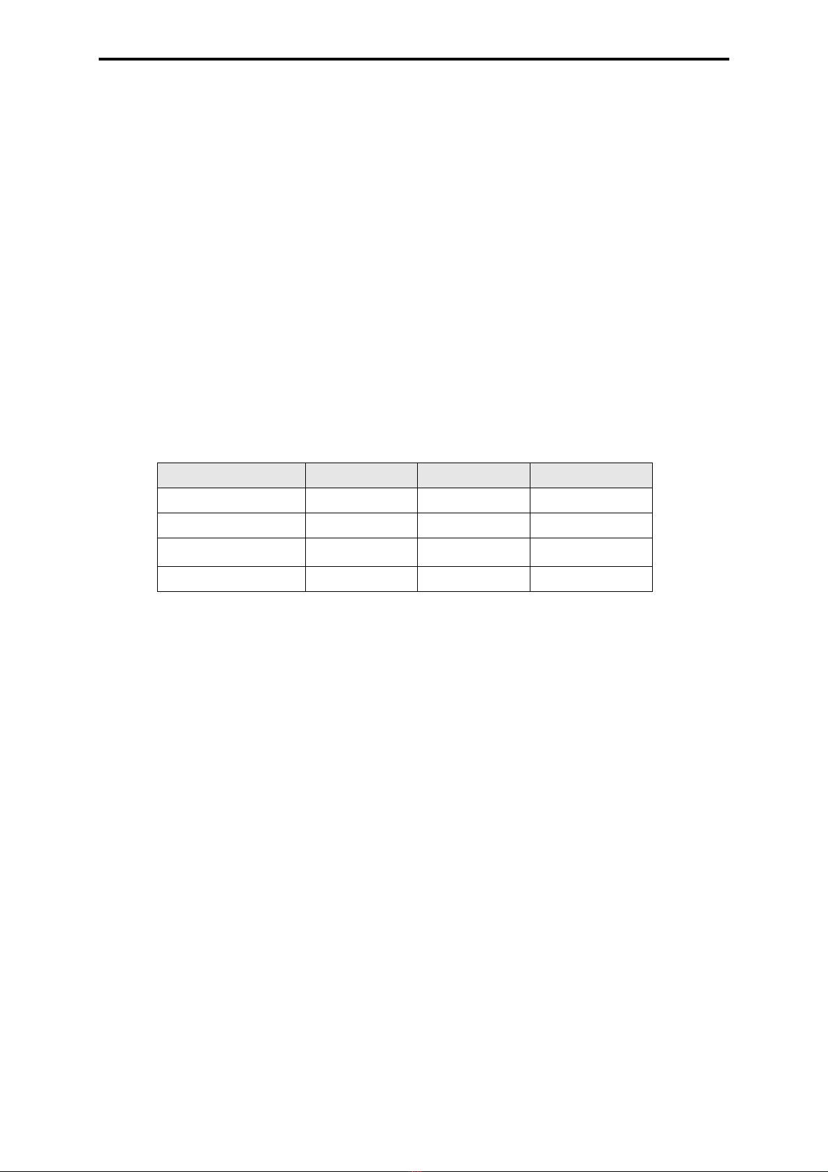
The following table gives an overview:
1) Individual I/O modules can also be used as redundant modules or connected to sensors in
a 2-out-of-3 voting to increase the availability.
The inputs have to be therefore configured on 3 different I/O modules.
Mono = single channel system structure
Redundant = redundant central modules and/or separated I/O bus system structure
Safety SIL 3 SIL 3 SIL 3
Availability normal (MS) high (HS) very high (HRS)
Central module mono redundant redundant
I/O modules mono 1) mono 1) redundant
I/O bus mono mono redundant
Table 1: Safety and Availability
Concept of the HIMA PES
4
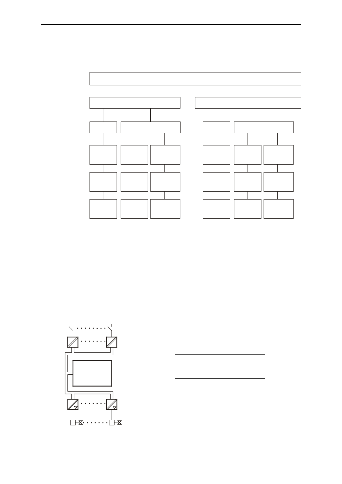
2.2 Designs and Types of the PES
The controls can be adapted to the requirements of the plant by equipping them with the ap-
propriate central modules. The following structures are possible with the H41q or H51q system
family:
* Central modules, communication modules and I/O modules are installed in the system sub-
rack.
Figure 1: Designs and Types of the PES
Notes:
Mono = single channel system structure
Redundant = redundant central modules and/or separated I/O bus system structure
SIL = Safety Integrity Level according to IEC 61508
I/O = input and output
2.2.1 Concept of H41q-M, MS / H51q-M, MS
Figure 2: Concept of H41q-M, MS / H51q-M, MS
Designs and Types of the PES
The H41q compact system The H51q modular system
Mono Redundant
normal
H41q-M H41q-H H41q-HR
TÜV
H41q-MS TÜV
H41q-HS
SIL 3
TÜV
H41q-HRS
- *
1
Mono Redundant
- *
1- *
2
normal
H51q-M
high
H51q-H
very high
H51q-HR
SIL 3
TÜV
H51q-MS
SIL 3
TÜV
H51q-HS
SIL 3
TÜV
H51q-HRS
16
116
12 x 8
2
Design
Availability
Type
Certificate
Type
Techn. features
Max. I/O-rack
I/O buses
Safety
Mono
high very high
SIL 3 SIL 3
I/O bus
I/O bus
CU
Input modules
Central module
Output modules
Characteristics
CU mono
I/O modules mono
I/O bus mono

Concept of the HIMA PES
5
H41q-M / H51q-M
single channel central module and single channel I/O bus
H41q-MS / H51q-MS
with double processors, safety-related
single channel central module and single channel I/O bus with TÜV certificate up to SIL 3 ac-
cording to IEC 61508
2.2.2 Concept of H41q-H, HS / H51q-H, HS
Figure 3: Concept of H41q-H, HS / H51q-H, HS
H41q-H / H51q-H
redundant central modules and a single channel I/O bus for highly available PES
H41q-HS / H51q-HS with double processors, safety-related
redundant central modules and a single channel I/O bus for highly available and safety related
PES with TÜV certificate up to SIL 3 according to IEC 61508
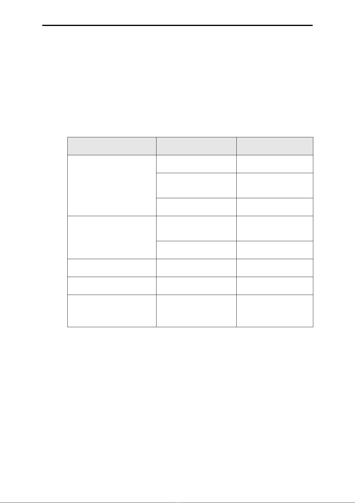
2.2.3 Concept of H41q-HR, HRS / H51q-HR, HRS
Figure 4: Concept of H41q-HR, HRS / H51q-HR, HRS
I/O bus
I/O bus
CU 2
Input modules
Central module
s
Output modules
CU 1
DPR DPR
Characteristics
CU redundant
I/O modules mono/
redundant
I/O bus mono
I/O bus
I/O bus
CU 2
Input modules
Central module
s
Output modules
CU 1
DPR DPR
I/O bus
I/O bus
Characteristics
CU redundant
I/O modules redundant/
mono
I/O bus redundant

Concept of the HIMA PES
6
H41q-HR / H51q-HR
Redundant central modules and two channel I/O bus for highly available PES.
H41q-HRS / H51q-HRS with double processors, safety-related
redundant central modules and redundant I/O bus for highly available and safety-related PES
with TÜV certificate up to SIL 3 according to IEC 61508
Remarks to the drawings:
CU = central module
I/O modules = input / output modules
I/O bus = bus system for inputs and outputs
DPR = Dual Port RAM
The H41q System Family
7
3 The H41q System Family
The H41q system family comprises compact designed PES in single channel and redundant
models, also with TÜV safety certificate.
All input/output modules can be used with both redundant and single channel models of the
central modules.
All modules of the H41q system family meet the requirements for electromagnetic compatibility
and immunity according to article 10 of the EG guideline 89/336/EWG for the electromagnetic
conformity. This is demonstrated with the CE sign within the data sheets of the modules. Also
the systems and modules are wearing a label with this sign.
All models of the H41q system family have all the components required for control tasks in one
19 inches subrack, 5 units high, with an integrated cable tray (see also data sheets of H41q
systems or assembly kits).
3.1 Overview Assembly Kits H41q
The components required for a working system are included in assembly kits:
* Options
Abbreviations: CM Coprocessor Module
CoM Communication Module
CU Central Module
I/O Input/Output
System H41q-M H41q-H H41q-HR H41q-MS H41q-HS H41q-
HRS
Safety – – – SIL 3 SIL 3 SIL 3
Quantity/type
CU
1 x
F 8653X
2 x
F 8653X
2 x
F 8653X
1 x
F 8652X
2 x
F 8652X
2 x
F 8652X
Quantity/type
CM *
1 x
F 8621A
(2 x) 1 x
F 8621A
(2 x) 1 x
F 8621A
1 x
F 8621A
(2 x) 1 x
F 8621A
(2 x) 1 x
F 8621A
Quantity/type
CoM
(Fast Ethernet) *
1 x
F 8627/
F 8627X
(2 x) 1 x
F 8627/
F 8627X
(2 x) 1 x
F 8627/
F 8627X
1 x
F 8627/
F 8627X
(2 x) 1 x
F 8627/
F 8627X
(2 x) 1 x
F 8627/
F 8627X
Quantity/type
CoM
(Profibus-DP) *
1 x
F 8628/
F 8628X
(2 x) 1 x
F 8628/
F 8628X
(2 x) 1 x
F 8628/
F 8628X
1 x
F 8628/
F 8628X
(2 x) 1 x
F 8628/
F 8628X
(2 x) 1 x
F 8628/
F 8628X
Quantity/type
power supply
1 x
F 7130A
2 x
F 7130A
2 x
F 7130A
2 x
F 7130A
2 x
F 7130A
2 x
F 7130A
Quantity
I/O buses
112112
max. quantity
I/O modules
13 13 7 + 6 13 13 7 + 6
Assembly kit
number
B 4234 B 4236-1 B 4236-2 B 4235 B 4237-1 B 4237-2
Table 2: Overview Assembly Kits H41q
The H41q System Family
8
3.2 Concepts of the Safety Switch-Off at H41q
In the system descriptions of the safety-related PES H41q-MS, -HS, -HRS the ways for shut-
down if a fault occurs are shown. Depending on the fault location the reactions of the systems
are fixed or they can be defined in the user program.
Parameters are set
– in the resource properties I/O parameter
– by activating of a system variable for emergency shutdown
– via function block H8-STA-3.
An overview of the system variables including the corresponding error code you will find in the
operating system manual.
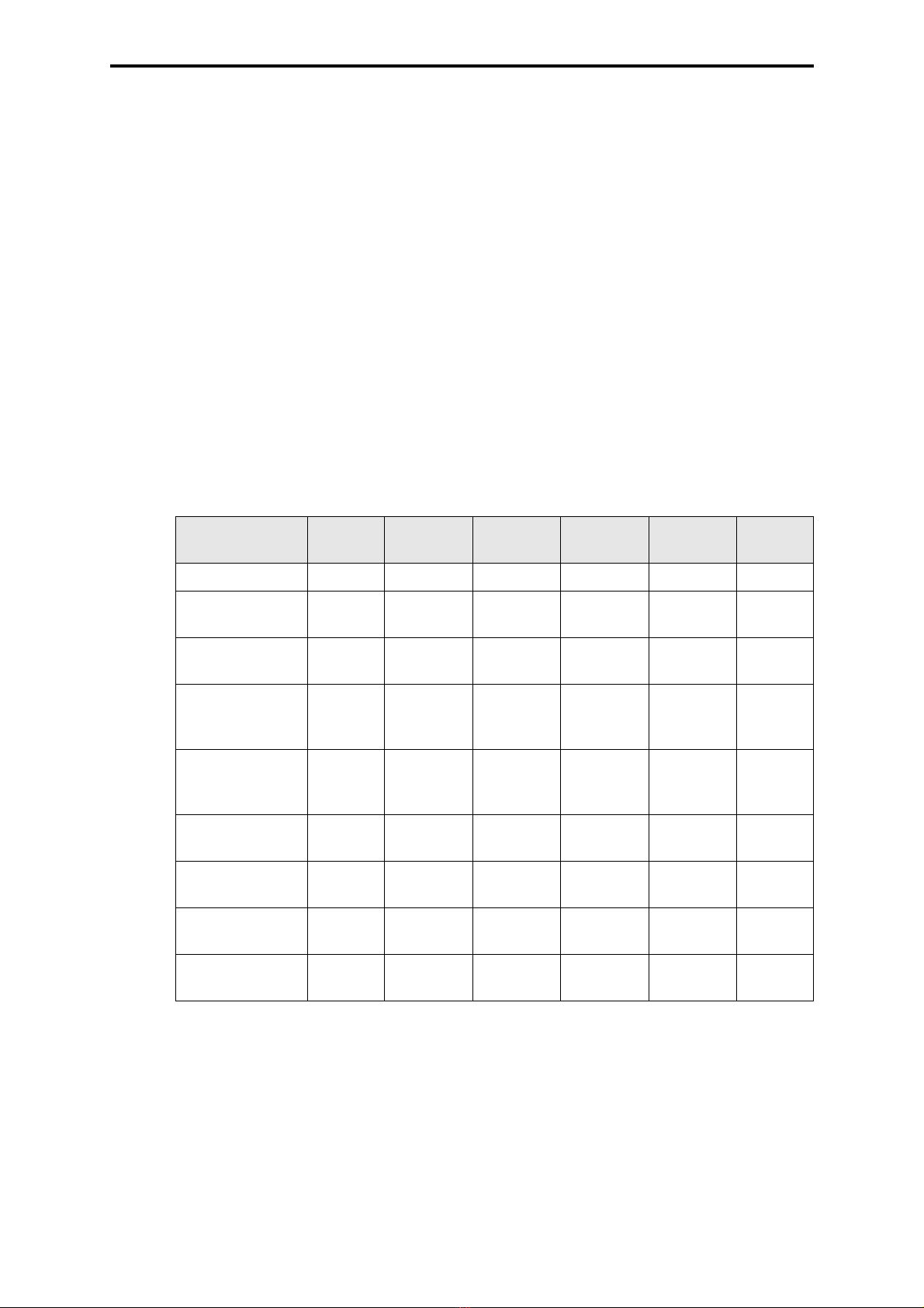
Reaction to faults of safety related digital I/O modules during operation:
Definition:
Double fault = fault within an output channel and the switch-off electronic part of this testable
output module.
Abbreviations used in the table:
CU Central Module
I/O bus Input/output bus
WD Watchdog signal
More explanations on the following page.
Location of fault I/O parameter in the pro-
perties of the resource Reaction of the system
Output modules
Single error
(also voltage failure)
- display only or
- normal operation
Module switch-off
- normal operation and
one function block
H8-STA-3 per group
Group shutdown
- Emergency off WD switch-off of the
appertaining CU
I/O bus or
double fault of
output modules
- display only Slot with error code in I/O
bus display of the CPU,
WD is still switched on
- normal operation or
- Emergency off
WD switch-off of the
appertaining CU
Central modules independent of the I/O
parameter
WD switch-off of the
appertaining CU
Input modules independent of the I/O
parameter
Operation of 0-signal for all
inputs of this module
Independent of a fault of the
output module
System variable for emer-
gency switch-off activated,
independent of the I/O
parameter
WD switch-off of the
appertaining CU
Table 3: Concepts of the Safety Switch-Off at H41q

The H41q System Family
9
Explanations to the table:
Parameter “Display only“
Switch-off by means of the integrated safety shutdown inside the output amplifier. If not possi-
ble then shutdown of the watchdog signal in the I/O rack by means of the coupling module (only
in systems H51q). No shutdown of the watchdog signal of the appertaining central unit. This
parameter is permissible only up to SIL 1.
Parameter “Normal operation“
Reaction as with parameter “Display only“, additionally switch-off of the watchdog signal of the
appertaining central unit if necessary. Parameterization required from SIL 2. Normal and re-
commended parameter.
Parameter “Emergency off“
Switch-off of the watchdog signal of the appertaining central unit and thus shutdown of the out-
put amplifiers in case of a fault in the output module.
The watchdog signal is not switched off at faults in the input modules.
Module switch-off
A faulty testable output module with integrated safety shutdown will be switched automatically
to the safe de-energized status.
Group shutdown
If it is requested, a group shutdown may be defined in the user program in a way that all test-
able output modules appertaining to the group with the faulty module are also switched off.
Inside the user program up to 10 testable output modules can be assigned to one group by
means of the function block H8-STA-3.
WD switch-off of the appertaining CPU
In case of a fault the watchdog signal (WD) of the appertaining central module is switched off.
If systems with redundant central modules and a common I/O bus are used then the output
modules are related to both central modules. In case of a fault both the watchdog signals of
the central modules are switched off. That means all the I/O modules are switched off (only at
H41q-H/HS).
If systems with redundant central modules and redundant I/O bus are used then the output
modules are related to one central module and one I/O bus. In case of a fault only the watchdog
signal of the related central module is switched off. That means only the related I/O modules
are switched off (only at H41q-HR/HRS). The redundant central module is still in operation.
3.3 The Input/Output Level
In the subrack, slots 1 to 13 are provided for the input/output modules. Any arrangement of
I/O module types is possible. In PES with redundant I/O bus, the modules on slots 1 to 7 are
assigned to the first I/O bus and 8 to 13 to the second I/O bus.
There is an integrated cable tray under the subrack. It is equipped with a receptacle for the
label which can be flapped open to provide easy access to the cables.
3.3.1 24 VDC Supply and Distribution
For 24 VDC supply and distribution we recommend to use the K 7212, K 7213, K 7214, K 7215
subassemblies or fuse distributor K 7915.
They include all components for the fusing of up to 18 individual supply circuits with circuit
breakers.
The K 7212 is additionally equipped with decoupling diodes and filters with monitoring relays
for mains supply.
Additionally you could use also a power supply of the PS1000 series (see ELOP II CD).

The H41q System Family
10
3.3.2 I/O Modules
The I/O modules are used for signal transfer and signal matching between the plant and the
central modules. The input and output circuits are always fed into the I/O modules via cable
plugs on the front side. The status of the digital output signals is shown on the LEDs of the
cable plugs. The power supply is either via the cable plugs or via the I/O bus board. The order
of the different I/O module types does not matter.
All I/O modules can be removed or inserted during operation (see chapter 8.1.1).
3.3.3 ATEX (Ex)i-Modules
The current (Ex)i modules exist in 2 construction models:
– non-varnished, with PCB covering
– varnished, with PCB covering
Any models can be equipped together without empty slots between them.
Non-varnished (Ex)i modules may combined together with non-(Ex)i modules without any re-
strictions. There are no free slots necessary on the left or on the right.
With varnished (Ex)i modules with PCB covering the right slot has to remain free in combina-
tion with non-(Ex)i modules, or has to be equipped with a front plate with partition plate
(M 2214). This is also valid for slot no. 15. The slot left to the (Ex)i module may be equipped
with any other module. Spare slots have to be covered by front plates M 2215 (4 spacing units
SU) or M 2217 (8 spacing units SU).
Usable front plates with partition or front plates:
M 2214 Front plate with partition plate 100 x 160 mm
M 2215 Front plate 4 SU
M 2217 Front plate 8 SU
Cable plugs for intrinsically safe circuits are marked and have coded pins, so that they can only
be plugged into the appropriate modules.
3.3.4 Safety-Related Output Modules for SIL 3
All the safety-related output modules meet the requirements of SIL 3.
The safety-related output modules have three semiconductors connected in series. That
means that more than the required second independent component for safety shutdown is now
integrated in the output module.
In case of a fault of an output module the requirements of SIL 3 are valid without time limit. In
the following this feature is called the integrated safety shutdown.
If a safety-related output module should fail during operation then it will be automatically
switched off by the integrated safety shutdown to get the safe de-energized status.
3.3.5 Special Features of the Output Modules
All output modules have the following special features:
– To increase the availability the outputs of the safety-related output modules can be
switched in parallel without external diodes.
Decoupling diodes are already integrated on the module (see the corresponding data
sheets).
– No output voltage is generated if the supply voltage L- is cut at the output module.
– The connection of inductive loads can be done without using protection diodes at the coil.
However, it is recommended to connect a diode directly at the inductive load avoiding
noise voltages.
– The LED signaling the output status is controlled separately.

The H41q System Family
11
– The design of the cable plugs enables the two-pole connection of the actuators. Together
with a two-pole supply of the output module an earth fault detection will be simplified by
means of a totalizing current transformer.
The cable plugs are available in two specifications:
• L- in cable plug, one-pole with common L-
• L- in 2-pole type, 2-pole with L- per channel
see also chapter 10.13.6 , “Description of the Order Code for Cable Plugs”, option P2
• No time-limited operation in case of a faulty output module.
3.4 System Voltage 24 VDC
HIMA systems will be connected to 24 VDC. The connection terminals are labelled with L+ and
L-. The power supply units made available by HIMA, e.g. the power supply PS1000, meet the
requirements according to CE for electrical safety and EMC.
All used power supplies must fulfill the requirements SELV (Safety Extra Low Voltage) or PELV
(Protective Extra Low Voltage). See also chapter 6.4.
The power supply units meet the requirements of the NAMUR recommendation NE 21 for the
safety during short-time voltage dips up to 20 ms.
For the supply of 24 V sources, which cannot guarantee a buffering during voltage dips of at
least 20 ms, the following measures must be taken in the H41q system family:
• decoupling of the power supply for the central units and
• noise blanking (parameterizable).
Note Due to the high inrush current of lamps the correct dimensioning of the
power supply units for lamp loads must be regarded.

The H41q System Family
12

The H51q System Family
13
4 The H51q System Family
The H51q system family comprises modular designed PES in single channel and redundant
models, also with TÜV safety certificate.
All input/output modules can be used with both redundant and single channel models of the
central devices.
All modules of the H51q system family meet the requirements for electromagnetic compatibility
and immunity according to article 10 of the EU guideline 89/336/EWG for the electromagnetic
conformity. This is marked with the CE sign within the data sheets of the modules. Also the
systems and modules are wearing a label with this sign.
The H51q system family consists of one 19 inches central rack, 5 units high, and up to 16 input/
output racks in the 19 inches size, 4 units high (see also data sheets for H51q systems or as-
sembly kits).
4.1 Overview Assembly Kits H51q
The components required for a working system are included in assembly kits:
* Options (max. 5 communication slots per central module)
Abbreviations: CM Coprocessor Module
CoM Communication Module
CU Central Module
I/O Input/Output
System H51q-M H51q-H H51q-HR H51q-MS H51q-HS H51q-
HRS
Safety – – – SIL 3 SIL 3 SIL 3
Quantity/type
CU
1 x
F 8651X
2 x
F 8651X
2 x
F 8651X
1 x
F 8650X
2 x
F 8650X
2 x
F 8650X
Quantity/type
CM *
3 x
F 8621A
2 x 3
F 8621A
2 x 3
F 8621A
3 x
F 8621A
2 x 3
F 8621A
2 x 3
F 8621A
Quantity/type
CoM
(Fast Ether-
net) *
5 x
F 8627/
F 8627X
2 x 5
F 8627/
F 8627X
2 x 5
F 8627/
F 8627X
5 x
F 8627/
F 8627X
2 x 5
F 8627/
F 8627X
2 x 5
F 8627/
F 8627X
Quantity/type
CoM
(Profibus-DP) *
5 x
F 8628/
F 8628X
2 x 5
F 8628/
F 8628X
2 x 5
F 8628/
F 8628X
5 x
F 8628/
F 8628X
2 x 5
F 8628/
F 8628X
2 x 5
F 8628/
F 8628X
Quantity/type
power supplies
2 (+1*) x
F 7126A
3 x
F 7126A
3 x
F 7126A
2 (+1*) x
F 7126A
3 x
F 7126A
3 x
F 7126A
5 V monitoring F 7131 F 7131 F 7131 F 7131 F 7131 F 7131
Battery
buffering
F 7131 +
F 8651X
F 7131 +
F 8651X
F 7131 +
F 8651X
F 7131 +
F 8650X
F 7131 +
F 8650X
F 7131 +
F 8650X
Quantity
I/O buses
112112
max. quantity
I/O modules
256 in
16 I/O
subracks
256 in
16 I/O
subracks
2 x 128 in
2 x 8 I/O
subracks
256 in
16 I/O
subracks
256 in
16 I/O
subracks
2 x 128 in
2 x 8 I/O
subracks
Assembly kit
number
B 5230 B 5232-1 B 5232-2 B 5231 B 5233-1 B 5233-2
Table 4: Overview Assembly Kits H51q

The H51q System Family
14
4.2 Concepts of the Safety Switch-Off at H51q
In the system descriptions of the safety related PES H51q-MS, -HS, -HRS the ways for shut-
down if a fault occurs are shown. Depending on the fault location the reactions of the systems
are fixed or they can be defined in the user program.
Parameters are set
– in the resource properties I/O parameter
– by activating of a system variable for emergency shutdown
– via function block H8-STA-3.
An overview of the system variables including the corresponding error code you will find in the
operating system manual.
Reaction to faults of safety-related modules during operation:
Definitions:
Double fault = fault within an output channel and the electronic switch-off part of a testable out-
put module
Abbreviations in the table:
CU Central Module
I/O bus Input/output bus
I/O subrack Input/output subrack
WD Watchdog signal
More explanations on the following page.
Location of fault I/O parameter in the pro-
perties of the resource Reaction of system
Output modules
single error
(also voltage failure)
- display only or
- normal operation
Module switch-off
- normal operation and
one function block
H8-STA-3 per group
Group shutdown
- Emergency off WD switch-off
of the appertaining CU
I/O bus within I/O subrack or
double fault in
output modules
- display only Slot with error code in I/O
subrack display of the
CPU,
WD is still switched on
- normal operation WD switch-off of the apper-
taining coupling module
- Emergency off WD switch-off
of the appertaining CU
Central modules (CU) or
I/O bus between CU and cou-
pling modules
independent of the I/O
parameter
WD switch-off
of the appertaining CU
Input modules independent of the I/O
parameter
Operation of 0-signal for all
inputs of this module
Independent of a fault of the
output module
System variable for emer-
gency switch-off activated,
independent of the I/O
parameter
WD switch-off
of the appertaining CU
Table 5: Concepts of the Safety Switch-Off at H51q
This manual suits for next models
1
Table of contents
Other HIMA Industrial Equipment manuals


