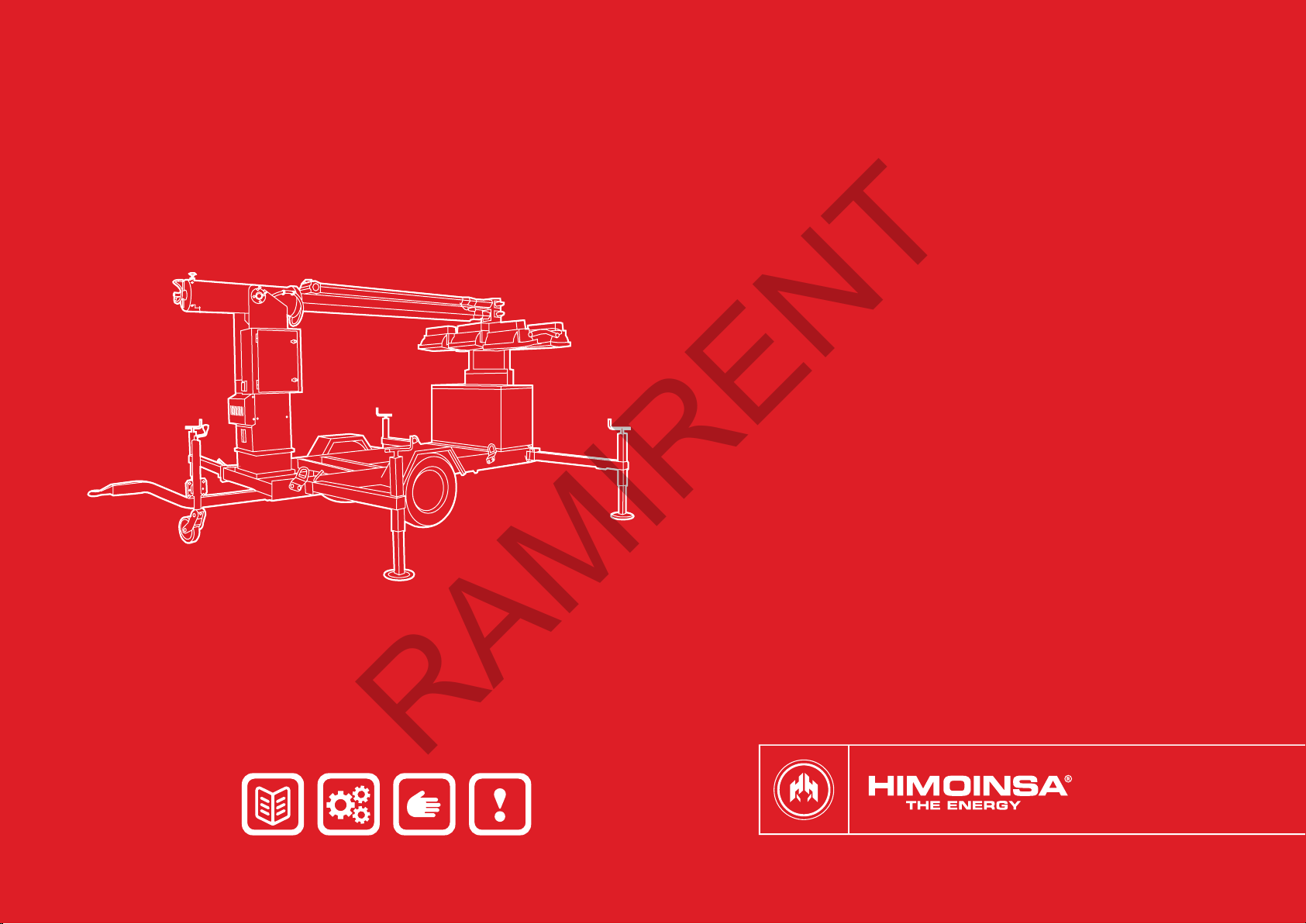
Himoinsa KT8000 Service manual
INSTALLATION, USE AND
MAINTENANCE MANUAL
LIGHTING TOWERS | APOLO KIT TOWER: KT8000, KT12000
RAMIRENT

LIGHTING TOWERS | PAG. 2
INDEX
3 1. Introduction
4 2. Safety regulations
7 3. Lighting tower: composition and location of its components
9 4. Technical information
10 5. Start up
14 6. Operations to carry out after use
15 7. Maintenance
15 8. Failures
16 9. Guarantee conditions
RAMIRENT

INTRODUCTION | PAG. 3
1. INTRODUCTION
By means of this handbook we intend to provide the basic instructions and
information for a proper installation, use and maintenance of the HIMOINSA
Lighting Tower.
All activities to do with the internal functioning of the tower and the generating
set that compose it, must be carried out by specialized personnel, with experience
in Diesel engines and mechanical installations as well as in generation of
electricity. This handbook and all the other reference documentation are
indispensable in order to prepare these specialists.
At Himoinsa we think of you, that’s why its essential that you thoroughly read all
safety regulations and warnings before you start the lighting tower, only by doing
this we can assure you an optimal service in perfect reliability and safety
conditions.
HIMOINSA advises that the validity of the information in this handbook refers to
the date that it was issued, as several aspects such as the technological
developments, new regulations or updates and improvements of the models
oblige us to make changes without notice, which may not appear in the current
manual.
This Handbook and the rest of the reference documentation, form part of the
lighting tower that you have purchased and must be kept and protected against
any agent that may damage them. This documentation must accompany the
equipment whenever it is leased to any other user or new owner. Although all the
information in this handbook has been thoroughly veried, HIMOINSA refuses any
responsibility for any spelling typographic or transcription errors.
In accordance with Directive CEE 85/374 and subsequent modication 99/34,
HIMOINSA will not be deemed responsible due to defective installations,
improper uses of the machine and non fullment of the regulations of this
manual.
RAMIRENT

SAFETY REGULATIONS | PAG. 4
2. SAFETY REGULATIONS
Before working on the machine carefully read the following safety regulations,
and nd out about the local requirements in safety.
The installation, operation, maintenance and repairs must be carried out only
authorized and competent personnel.
The owner is responsible for the maintenance of the Lighting Tower in good safety
conditions. The parts and accessories must be replaced if they are not in good
functioning conditions.
2.1 GENERAL SAFETY PRECAUTIONS
•Do not allow non-authorized people to be close to the Lighting Tower.
•Do not allow people with pacemakers to get close to the tower as it
may cause electromagnetic interferences on these devices.
•Do not get close to the Tower wearing loose clothes or objects that
may be attracted by the airow or by the mobile parts of the engine.
•lt is forbidden to dismount or disable any safety device.
•lt is forbidden to lean on the Lighting Tower or leave objects on it.
•Lower the mast when wind speed exceeds 80km/h.
•Do not tow the lighting tower trailer on the highway at speeds
exceeding 90km/h.
lf the Lighting Tower is driven by automatic driving sets, it is necessary to:
•Place a red light that switches on when the unit is working, in a
visible place.
•Place a warning sign warning of the possibility that and automatic
unexpected start up of the machine may occur.
•Place an obligations sign stating: “All maintenance operations must
be carried out with the genset in the LOCK position”.
•For the emergency stop of the group, press “emergency stop” push
button, located in the group or the emergency push button to be
installed outside the engine room.
RAMIRENT
SAFETY REGULATIONS | PAG. 5
Once the pole is totally opened, verify the following points:
•The mast must be totally perpendicular to the ground.
•The feet must be in touch with the ground.
•All xings must be locked.
•Do not move the tower when the ood lights are on. The high
temperatures that the laments of the lights reach, make them very
vulnerable to small vibrations, therefore we recommend switching off
the oodlights 1O minutes before moving the equipment.
•Do not fold the mast of the unit without having lowered it.
•Do not open the pressure control valve at the bottom of the mast
when it is opened.
2.3 SAFETY DURING INSTALLATION AND FIRST START UP
•For provisional installations, it will just be enough to place the unit on
a well levelled surface, for installations for a longer period of time, its
advisable to build foundations. The installation of the Generating set
and all its accessories must be carried out by specialized personnel.
lf any difculty, consult the Himoinsa Technical Department.
•You must know all the emergency procedures related to the
installation to be done.
•Always use a protective hard hat, safety boots and gloves, safety
goggles and tight clothes.
•Do not change the original protections, located on the rotary exposed
parts, over the hot surfaces, air intakes, belts and parts in tension.
•Do not leave dismounted parts, tools or any other accessory on top
of the engine or nearby or at the premises of the genset.
•Never leave ammable liquids or cloths soaked with ammable
liquids near the generating set, near electrical devices or parts of the
electrical installation (including lamps).
•Take all precautions possible in order to avoid are risks; check that
there is a grounds installation and that has been made according to
Regulations.
•Place a sign “NO MANOEUVRING” in all the sectioning organs that
insulate the parts of the installation on which you must work.
•lnsulate all disconnected links and wires. Do not leave uncovered the
voltage terminals of the generator.
•Connect the grounds installation to all the connexion relative points
prepared in the unit and its accessories.
2.2 SAFETY AT DELIVERY, STORAGE AND UNPACKING
•Once you receive the lighting tower check that the goods received
correspond to those on the delivery note and that all the goods are in
perfect conditions.
•To lift and transport the Tower, lifting machines the appropriate
capacity must be used. All loose and pivoting parts must be safely
xed before lifting it.
•When moving the lighting Tower and specially when lifting it , it is
recommended to use the available points for its safe and easy
movement.
•lt is totally forbidden to use any other lifting points located over the
engine, alternator or other components.
•lf the lighting Tower is damaged for any reason during its
transportation, storage, and/or mounting, it mustn’t be started up
before it is veried by our specialized personnel.
•lf you want to store the Tower until its utilization, it is highly
recommendable to have a warehouse properly protected against any
chemical agent that may damage its components.
•Unpacking must be carried out carefully, avoid causing any damages
to the goods during such operation, especially when using levers,
saws or any other metallic tools.
WARNING
Do not place the mast in vertical position, before opening the levelling feet or
before stabilizing the mast over a rm and regular surface. The Tower could
overturn causing serious physical and / or material damages.
RAMIRENT

SAFETY REGULATIONS | PAG. 6
•Verify and check that the voltage connections as well as the auxiliary
services have been made properly.
•When installing the battery, rst connect the positive terminal and
after the negative one. Negative pole to the engine block.
•Check the cyclical direction of the phases is according to the mains.
•lndividualize the position of the emergency stop button pushers, the
quick fuel interception valves, the switches and any other emergency
systems present in the installation.
•lsolate all the connections and disconnected threads. Don’t leave
open the terminals of power of the generator.
RAMIRENT

LIGHTING TOWER: COMPOSITION AND LOCATION OF ITS COMPONENTS | PAG. 7
3. LIGHTING TOWER: COMPOSITION AND
LOCATION OF ITS COMPONENTS
3.1 COMPOSITION
The KT8000 and KT12000 lighting towers are basically composed of:
•Mobile kit with automatically extendible mast.
•Generating set.
3.2 LOCATION OF ITS COMPONENTS
3.2.1 TELESCOPIC MAST
Consisting of 3 expansions made in extruded aluminium T6 and anodized with a
15 microns layer.
3.2.2 SUPPORT FOR SIX PROJECTORS
•KT8000: Made of quartz iodine with 1.500W power and a ow of
33.100 lumens each. The tower has a lighting capacity of 198.000
lumens, covering a surface area of 16,500 square metres.
•KT12000: Made of metal halide with 2.000W power and a ow
of 220.000 lumens each. The tower has a lighting capacity of
1.320.000 lumens, covering a surface area fo 110.000 square
metres.
3.2.3 MAST SUPPORT
Among other functions, houses and protects the electrical motor that drives all
the hydraulic system of the mast.
RAMIRENT

LIGHTING TOWER: COMPOSITION AND LOCATION OF ITS COMPONENTS | PAG. 8
3.2.5 REAR CABINET
With manual lock with key and foam protection, designed in order to keep the 6
projectors during transportation.
3.2.6 MOBILE KIT
Composed of a rigid shaft, articulated nozzle (optional) (1), hooking on eye (2),
hiding jockey wheel (3), 4 extensible legs protected with nylon in all their surface
(4), on the chassis it has 4 lifting eyes clearly indicated (5).
1 2 3 4 5
23 5 4 5 4
1
3.2.4 WATERPROOF CONTROL AND MANEUVERING SHELTER
Houses and protects in its interior the mast control automatic central, the
maneuvering panel and the generator set- tower connection hose.
RAMIRENT
TECHNICAL INFORMATION | PAG. 9
4. TECHNICAL INFORMATION
Ligthing tower KT8000 KT12000
Tower Model KT8000 T5/T6 KT12000 T5/T6
Voltage (3P + N + T) V 400 - 220 400 - 220
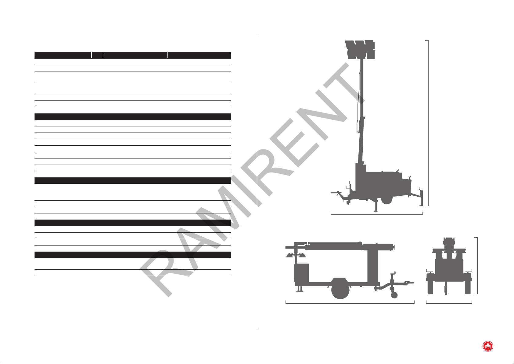
Maximum dimensions (wor-
king mode)
mm 4254 (L) x 3262 (W) x 9408 (H) 4254 (L) x 3262 (W) x 9675 (H)
Minimum dimensions (trans-
port mode) mm 4524 (L) x 1578 (W) x 2146 (H) 4524 (L) x 1578 (W) x 2146 (H)
Dry Weight Kg 970 1345
Consumption Diesel Diesel
Mast
Mast type Hydraulic Hydraulic
Mast sections 3 3
Rotation 360º manual 360º manual
Double safety block Standard Standard
Lamps nº 6 x 1500 W 6 x 2000 W
Lamps type Quartz Iodine Metal Halide
Total lumnes 6 x 33.000W = 198.000 6 x 220.000W = 1.320.000
Illuminated surface 16.500 m2110.000 m2
Waterproof control and maneuvering shelter
Control press buttons
protection, panel and
connection hose with genset
Standard Standard
Protection level IP66 IP66
Maneuver press buttons 2 (1 x rising, 1 x descending) 2 (1 x rising, 1 x descending)
Features
Wheels Jockey wheel Jockey wheel
Stabilisers 4 4
Lifting eyes
4
4
Generating set
Canopy (Standard Fuel Tank:
100L) B10 B10
Trailer kit xation Safety bolts Safety bolts
Safety bolts 1578 mm
4254 mm
9408 mm (KT8000)
9675 mm (KT12000)
2146 mm
RAMIRENT
START UP | PAG. 10
5. START UP
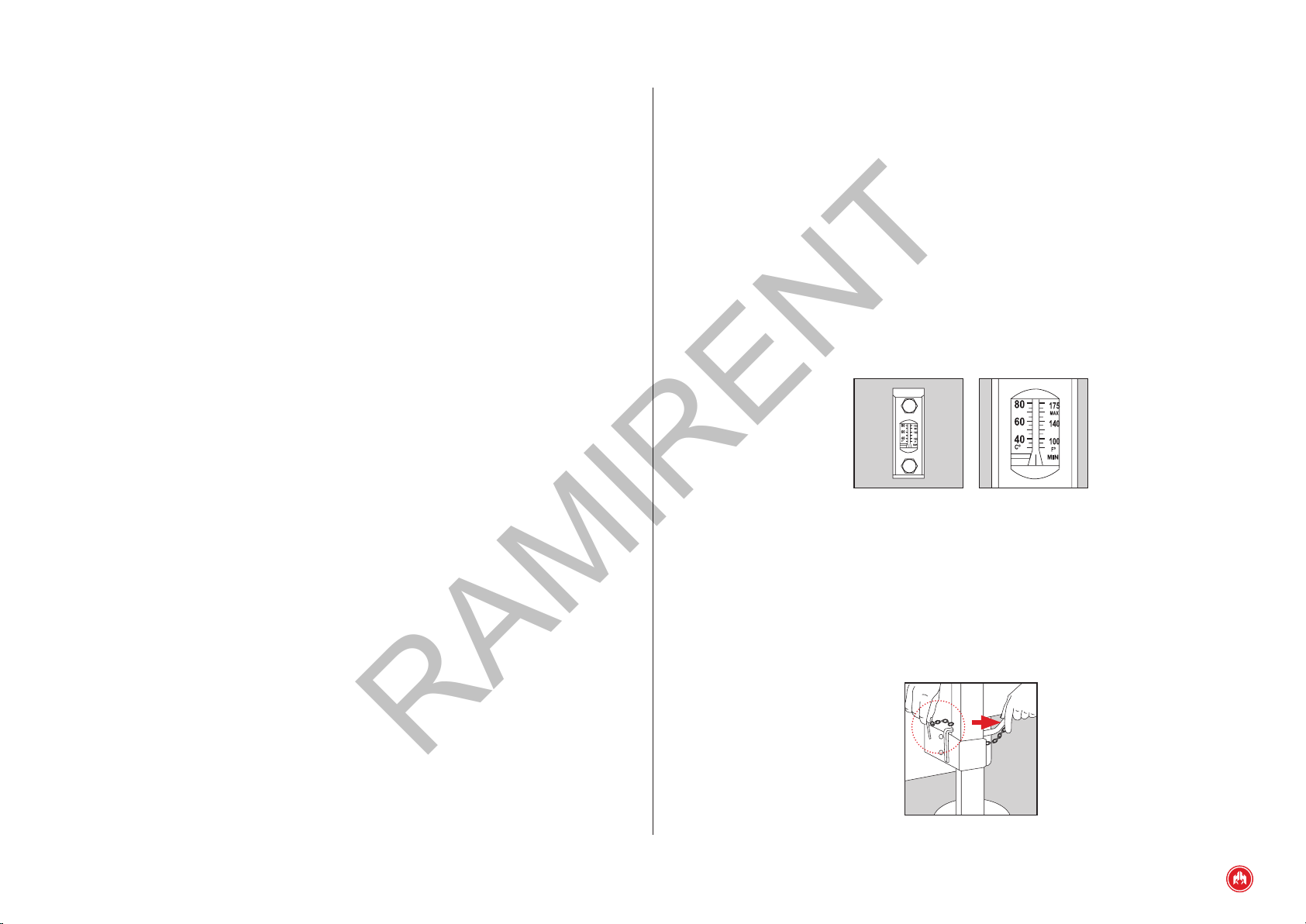
5.1 LEVELS
Check all levels of the equipment.
Hydraulic oil level: it can be checked by looking at the indicator that is on the
front side of the oil tank (under the motor). lt must be done when the tower is
resting and it has to be at least % of the total.(
Hydraulic oil temperature: this level also incorporates a Mercury temperature
meter in the center thereof so that the customer can respect working properties
of the oil. Some oils can lose properties above or below certain temperatures.
For water, oil and diesel levels of the genset, see generating set manual.
Fig.1
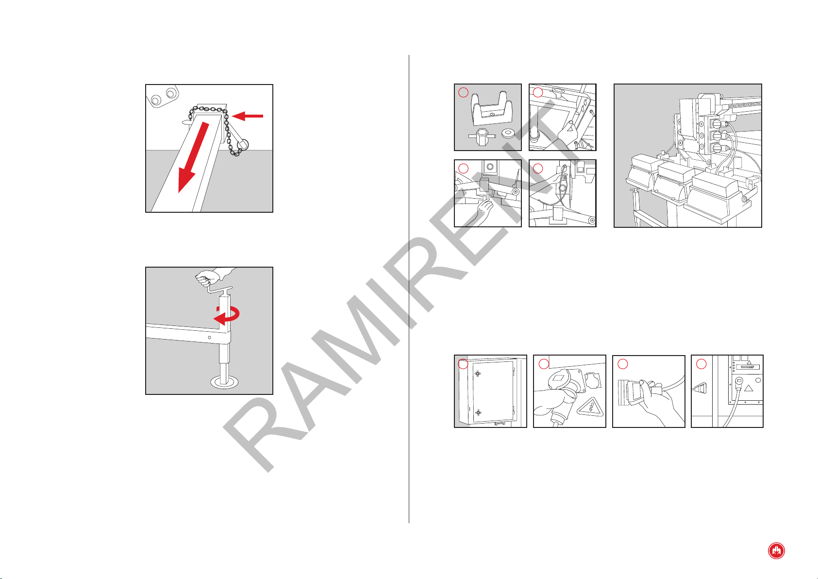
5.2 ANCHORAGE
As described in the safety chapter, do not raise the mast before opening the
levelling feet and stabilizing the tower on a rm and regular surface, in order to
do so, follow the steps bellow:
•Take out the safety brackets of the pins. (Fig. 2)
•Pull out the pins vertically. (Fig. 2)
Fig.2
RAMIRENT
START UP | PAG. 11
Once all spotlights are in place connect each one to its corresponding socket
(Fig. 4).
43
1 2
5.4 CONNECTING THE GENERATING SET TO TOWER
Once you have veried the connexion and the proper xing of the spotlights, we
will connect the generating set to the lighting tower. (Fig. 4).
In order to carry out this operation, get the extension cable that is in one of the
side compartments (Fig. 1) and connect one of the ends to the corresponding
power output located in the generating set (Fig. 2) control panel and the other
end to the lighting tower (Fig. 3).
1 2 3 4
5.5 STARTING UP THE GENERATING SET.
As shown in the start up procedure described in the instructions of the generating
set. (See Genset manual).
•Extract the legs. (Fig. 3)
•Put the safety brackets back in again. (Fig. 3)
Fig.3
•Turn the uppermost handle on the telescopic spindle bearings until it
grips there is a certain resistance. In this way one can balance and
x the tower to the chosen work surface. (Fig. 4)
Fig.4
5.3 INSTALING THE SPOTLIGHTS
Place the supplied spotlights in their corresponding slots, xing them with the
wingnuts located at the end of the mast.
In order to carry out this operation, unscrew the wingnut and remove the
supporting bracket (Fig. 1). Fit the spotlights (Fig. 2) with the glass upwards,
place the supporting bracket which grips the spotlight mounting, then the wingnut
and tighten it rmly (Fig. 3).
RAMIRENT
START UP | PAG. 12
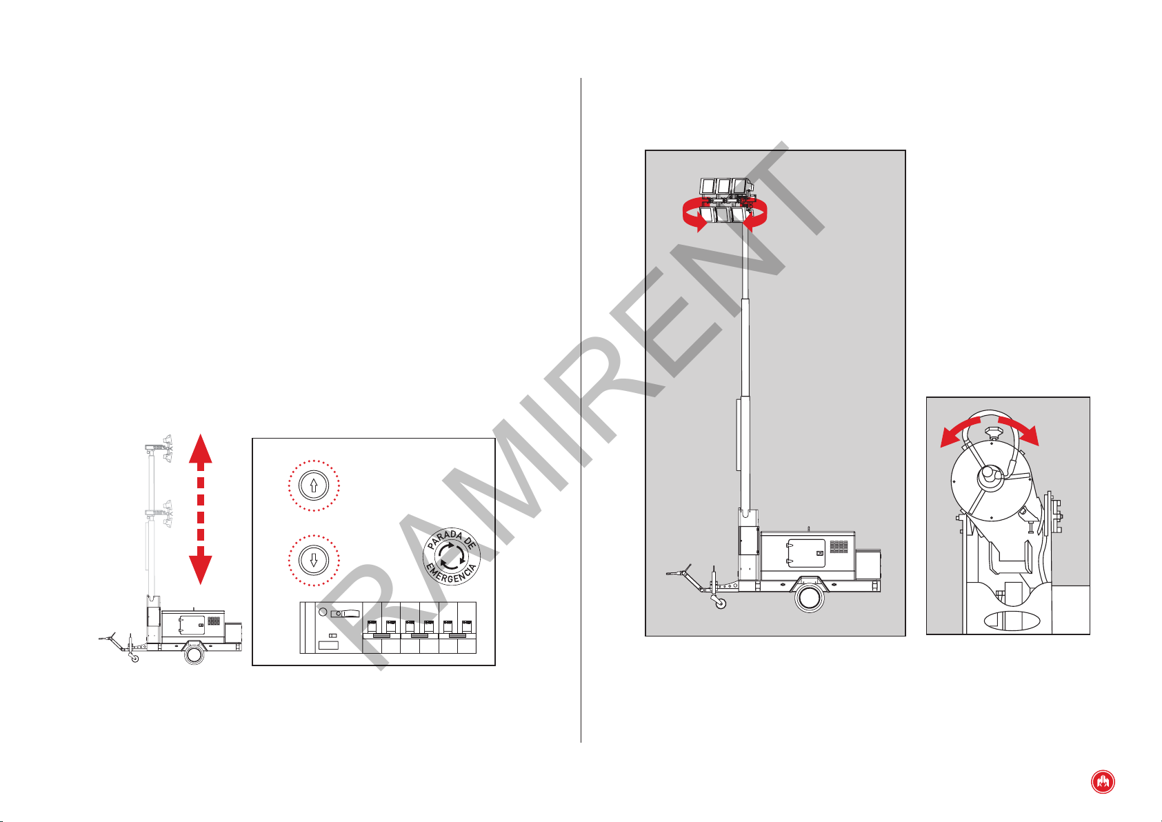
•Projectors direction: To give the projectors direction we must rst
unblock the lockscrew of the mast (Fig. 2) to turn the handwheel
located on the base of the mast. This orientation allows a 355º mast
rotation and offers a 360º of lighting eld.
Fig.2
5.6 STARTING THE ELECTRICAL MOTOR
In order to raise the mast you must connect the main switch at the tower control
panel (panel located in one of the side compartments) This switch feeds the
electrical motor of the Lighting Tower which will allow raising and unfolding the
mast in its all.
5.7 MAST START CONTROL & PROJECTORS ORIENTATION/DIRECTION
•Mast start control: lt allows the control of the mast through two
simple maneuver press buttons located at the waterproof and
maneuvering shelter (Fig. 1). Before moving the mast, it is necessary
to start the electrical engine as described previously. Moreover, it is
crucial to anchor and level out the tower with the extensible side legs.
The maneuver press buttons only allows safe movements of the mast.
This means that you will not be allowed to spread out the mast until the
mast is not completely perpendicular to the oor. Therefore you will not be
allowedtopull themast downuntil theevreysectionisnotaleradycleared.
The top button controls the slope angle regarding the horizontal (Oº
transport position, 9Oº working position), and the mast raising from is
vertical startign position up to 8.9 meters.
Fig.1
RAMIRENT

START UP | PAG. 13
5.8 SAFE POSITION WHEN WORKING
For working security, we recommend that when the mast and the projectors reach
the suitable position, close the hydraulic circuit key located on the base side of
the mast (Fig. 3) in order to avoid unexpected movements and mast falls because
of a loss of load.
Fig.3
5.9 SWITCHING ON THE SPOTLIGHTS
To switch on the spotlights, it was enough with connecting the main switch (Fig.
1) located inside the tight closet of control and it maneuvers (Fig. 2), next to
work the three switches next to the main one that they light the focuses s.
21
2 spots 2 spots 2 spots
Main
interruptor ON
RAMIRENT

OPERATIONS TO CARRY OUT AFTER USE | PAG. 14
6. OPERATIONS TO CARRY OUT AFTER USE
6.1 SWITCHING OFF THE SPOTLIGHTS
In order to turn off the spotlights, you just have to disconnect the three switches
inside the control and manoeuvring waterproof cabinet (on the right side of the
main switch).
6.2 FOLDING THE MAST
View 5.7 a) Mast start control (pag. 12)
6.3 MAIN SWITCH DISCONNECTION
Disconnect the main switch in the control and manoeuvring panel.
6.4 STOPPING THE GENSET
Follow the instructions for the generating set.
6.5 DISCONNECTING THE GENSET FROM THE TOWER
Disconnect the prolongador and keep it in the rear cabinet.
6.6 DISCONNECTING THE SPOTLIGHTS
Disconnect the spotlights, dismount them and carefully put them in their
compartments.
6.7 FOLDING OF THE TELESCOPIC SPINDLE BEARINGS
Fold the telescopic spindle bearings and dismount the extensible legs.
RAMIRENT

MAINTENANCE AND FAILURES | PAG. 15
7. MAINTENANCE
It is necessary to check the hydraulic oil level every time the lighting tower is
started, and to be cleaned more frequently when working in dusty environments
and it must be relled when necessary.
The packing of the hydraulic bottles must be checked every time the lighting
tower is started.
The lubrication of the lower bolt of the hydraulic bottle has to be carried out every
time we start the lighting tower.
The hoses must be checked every time start up and be replaced when necessary.
In case of blown bulbs, it is advisable to use gloves or a cloth. Don not touch the
bulbs with the ngers. We must frequently clean and dry the lighting tower when
operating it in a humid and dusty environment
In case of doubt contact our technical service.
8. FAILURES
Due to the simplicity of the system, the number of failures is practically zero.
However, in case of any anomaly, please contact our technical service.
RAMIRENT

GUARANTEE CONDITIONS | PAG. 16
9. GUARANTEE CONDITIONS
PROFESSIONAL USE (commercial) (whichever is first)
2.000 working hours.
12 months from the date of the sale.
15 months after leaving the factory.
RESIDENTIAL USE (private) (whichever is first)
2.000 working hours.
24 months from the date of the sale.
27 months after leaving the factory.
The coverage of this warranty is ONLY applicable to the end user of the equipment
recognized by Himoinsa. In the case of Generating sets, it is only applicable to
those generating sets that operate together with an manual or automated control
panel manufactured or/and installed by HIMOINSA. The Generating sets of 3,000
rpm have a 6 months warranty or 500 hours of continuous work, or 12 months or
1,000 hours in standby or emergency, whichever period expires rst.
Except when agreed, the products sold as used will have an only 3 month
warranty. This Warranty benets only the rst purchaser and can not be tranferred
to a thrid-party (nal purchaser) without previous authorization from/of HIMOINSA.
RAMIRENT

GUARANTEE CONDITIONS | PAG. 17
9.1 COMPANY RESPONSABILITIES
•In those countries where HIMOINSA may have an authorized technical
assistance Network (information available at (www.himoinsa.
com) the warranty consists of the replacement or reparation of
the damaged parts once checked its due to defective material at
origin, manufacturing or/and assembly, therefore , it covers both
the replaced parts as well as the manpower used during the normal
working hours. The customer shall be charged with transport
expenses to the premises of the authorized distributor, where the
repairs shall be carried out.
•The warranty for the rest of the world consists of free supply on
premises San Javier (Murcia # Spain), of the non usable parts due
to defective material at origin, manufacturing or/and assembly. If the
equipment is sent to our premises, all necessary repair tasks will be
carried out free of charge.
•In this case, transport both sending and return will be chargeable to
the customer.
•The warranty will only be given after the technical study of the
defective parts. Any part sent or service carried out before the
acceptance of the warranty will be billed. All replaced parts have to
be returned to Himoinsa and will become of its property.
•In case of defects in the motor or alternator, HIMOINSA informs that
the assistance of the warranty will be provided by ofcial technical
services of the manufacturer of the alternator or motor, who will
determine the scope of the warranty.
•The defect shall appear during the normal use of the product and
within the warranty period. The company will supply the necessary
spare parts for the repair as soon as possible but shall not be
deemed responsible for any losses for not having the equipment
during this period.
•All claims made based on this warranty, must be processed through
your authorized seller or area distributor, who will process the claim
and the scope of the warranty.
•This warranty does not cover failures or defects consequence of
its normal use or wear, inappropriate use (including overload and
overvoltage), negligence, accidental damages, non authorized
modications; lack of or inappropriate maintenance or connection,
(inappropriate storage, transrportation or installing); any kind of use
of the equipment over the capacity and limits established by the
manufacturer or under conditions different from those recommended;
failures caused after the failure or defect had or should have been
detected; batteries, lamps and fuses damages; damages due of
use of parts not supplied or manufactured by the manufacturer.
The Warranty also does not cover the rental costs of substitution
equipments during repair period nor connection costs and/or
connection works of the product with other equipments of the
customer.
•The repaired or replaced parts have a (6) six month warranty, this
will not modify the warranty of the other elements.
•Equipment or components not manufactured by the company.
The company will provide a warranty equal to the one supplier,
and limited to the responsibility offered by the company for its
equipment.
•All claims to do with the fuel injection system or parts of it, will be
referred by HIMOINSA to the manufacturer of the injection system,
or to its authorized agent. The manufacturer or authorized agent’s
report ON THE FAILURE will be binding for both parties : Himoinsa
and purchaser.
9.2 USER RESPONSABILITIES
The user is responsible to:
•Install and operate the product in accordance with the operation
and instruction manual provided, and in its case with the
assistance of qualied technical personnel and in accordance with
the current regulations.
•Carry out a proper maintenance of the equipment; (including the
use of appropriate fuel, oil, antifreeze, and lubricant), as well as to
replace of the parts and components due to the normal use of the
equipment.
•Return the warranty register form properly lled in within 1O days
after the start up of the product, or a month after the date of the
sale, whichever is rst.
•Send written notication to the company or to authorized Technical
assistance service in his country, of the failures of the material
and justify them within seven days after the failure appeared and
in any case before the expiration of the warranty, otherwise the
purchaser may lose his warranty rights.
•If the repair of the defect requires the participation of other
equipments not manufactured by HIMOINSA, the purchaser will be
the only responsible for the works and costs resulted as well as to
provide full access to the products manufactured by HIMOINSA S.L.
RAMIRENT

GUARANTEE CONDITIONS | PAG. 18
•Accept the technical report about the existence or non existence of
defects in the material or the assembly.
•The manpower costs , except for those stated in the section
“COMPANY RESPONSIBILITIES”, including those ones derived from
the assembly and disassembly of the equipment .
•The costs and risks from transportation or shipping of the equipment,
and any other costs associated with the replacement of the
components.
•Any cost that may exceed the purchasing price of the product.
•Any other cost, including transport and trips, accommodation, taxes
and fees, communication expenses, extra hours among others;
except for those stated in section #Company responsibilities#
•Payment of the total price of the machine, spare parts and related
services related with the product under warranty.
•The attendance of sales or technical personnel to the #start-up#
or #functioning demonstration# of the equipment will not mean
that the present warranty may be extended to the installation or
mounting, operation expressly excluded from this warranty; it also
does not imply acceptance or understanding of the correct technical
installation, assembly or/and connexion of the machine carried out
by the purchaser or a third party unconnected with Himoinsa, neither
of the dimensioning of the equipment purchased regarding the real
power supply need of the purchaser.
The present warranty will not be applicable to the following cases:
•When the documentation (warranty, purchasing invoice, maintenance
and use manual) may have been altered in any way or may be
illegible.
•If the model and serial number of the generating set have been
altered, erased, removed or are illegible.
HIMOINSA shall not be deemed contractually or extra contractually responsible
for any material or immaterial, direct nor indirect damages; consecutive or non-
consecutive to the damage on the material covered by the warranty, such as
operating losses, expenses and costs due to not having the product, neither for
damages to third parties or to other equipment or products.
This Warranty does not limit any other rights that as a consumer, the purchaser
may have according to the current legislation. This warranty replaces any other
express or implied warranty, including, without limitation any merchantability
warranty of the equipment or its suitability for a particular purpose. All claims not
covered by the above stipulations will not be accepted by the company.
HIMOINSA Informs the user of the obligation to follow the Maintenance and use
Manual and to keep it together with the rest of the technical documentation of
the equipment in observance with the safety at work regulation as well as the
convenience of installing specic protections that may prevent overvoltage and
overload from the main electrical line, and to protect the equipment by seeking
advice of an authorized installer.
RAMIRENT

HIMOINSA se reserva el derecho de modificar cualquier característica
sin previa notificación. Las ilustraciones pueden incluir equipamiento
opcional y/o accesorios. Imágenes no contractuales. Las indicaciones
técnicas descritas en este manual se corresponden con la información
disponible en el momento de la impresión. HIMOINSA ® - 2015 ©Todos
los derechos reservados.
© HIMOINSA - October 2015
FACTORIES
SPAIN • FRANCE • INDIA • CHINA • USA • BRAZIL
SUBSIDIARIES
PORTUGAL | SINGAPORE | POLAND | UAE | PANAMA
MEXICO | GERMANY | ARGENTINA | ANGOLA | UK
HEADQUARTERS
Ctra. Murcia - San Javier, km 23.6
30730 SAN JAVIER (Murcia) SPAIN
TLF. +34 968 19 11 28 | +34 902 19 11 28
Fax +34 968 19 12 17 | Export Fax +34 968 33 43 03
www.himoinsa.com
RAMIRENT
This manual suits for next models
1
Table of contents
Other Himoinsa Lighting Equipment manuals


