HindlePower AT30 SERIES Training manual

AT30 SERIES
Operating and Service Instructions
MICROPROCESSOR-CONTROLLED
FLOAT BATTERY CHARGER
THREE PHASE INPUT
(25 - 1,000 Adc)
JA5011-03
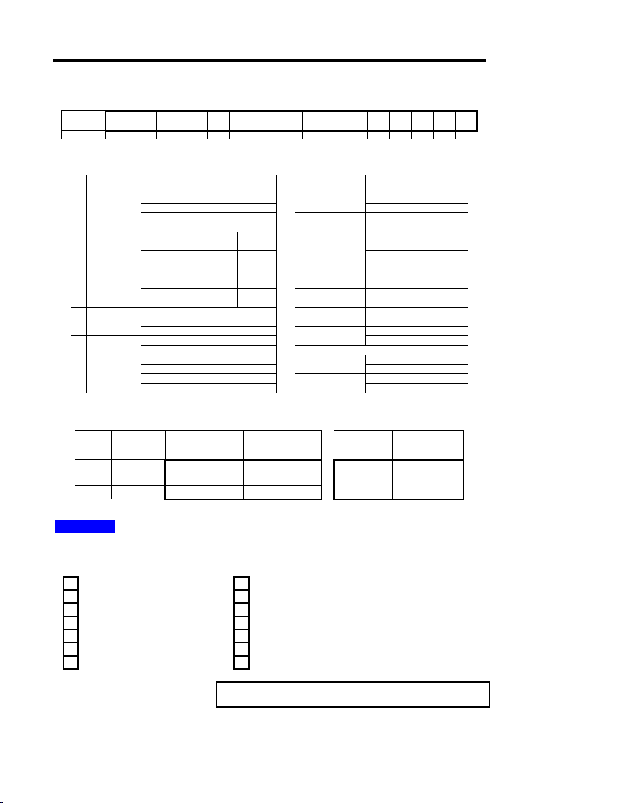
HOW TO READ THE AT30 MODEL NUMBER
The AT30 configured model number is coded to describe the unit's features and options. Please identify
the model number printed onthe data nameplate decal, and write it in the spaces provided below.
AT30
A B C D E F G H J K L M N P
Follow the chart below to determine the configuration of the AT30.
DESCRIPTION CODE FEATURE DESCRIPTION CODE FEATURE
A SERIES AT30 AT30 BATTERYCHARGER S STANDARD
012 12 Vdc M MEDIUMAIC
024 24 Vdc H HIGH AIC
048 48 Vdc
F
AC CIRCUIT
BREAKER
RATING
(SEE TABLE) 0 NO AC BREAKER
B NOMINAL
DC OUTPUT
VOLTAGE 130 130 Vdc F SUPPLIED
CODE FEATURE CODE FEATURE G AC FUSES
(200 kAIC) X NOT SUPPLIED
025 25 Adc 200 200 Adc S STANDARD
030 30 Adc 250 250 Adc M MEDIUMAIC
040 40 Adc 300 300 Adc H HIGH AIC
050 50 Adc 400 400 Adc
H
DC CIRCUIT
BREAKER
RATING
(SEE TABLE) 0 NO DC BREAKER
075 75 Adc 500 500 Adc F SUPPLIED
100 100 Adc 600 600 Adc J DC FUSES
(20 kAIC) X NOT SUPPLIED
125 125 Adc 800 800 Adc A SUPPLIED
C NOMINAL
DC OUTPUT
CURRENT
150 150 Adc 1K0 1,000 Adc K AUX ALARM
RELAYBOARD X NOT SUPPLIED
U UNFILTERED G SUPPLIED
F FILTERED (STANDARD) L COPPER
GROUND BUS X NOT SUPPLIED
D DC
FILTERING E BATT ELIMINATOR FILTER L SUPPLIED
208 208 Vac 60 Hz M LIGHTNING
ARRESTOR X NOT SUPPLIED
240 240 Vac 60 Hz
480 480 Vac 60 Hz F APPLIED
220 220 Vac 50/60 Hz N FUNGUS
PROOFING X NOTAPPLIED
380 380 Vac 50/60 Hz S APPLIED
E AC INPUT
VOLTAGE
416 416 Vac 50/60 Hz P STATIC
PROOFING X NOTAPPLIED
DESCRIPTION CODE FEATURE DESCRIPTION CODE FEATURE
INPUT AND OUTPUT INTERRUPTING CAPACITY RATINGS
ORDER
CODE
CIRCUIT
BREAKER
TYPE
AC CIRCUIT
BREAKER RATINGS
(208/240/480 Vac) *
DC CIRCUIT
BREAKER RATINGS
(125/250 Vdc)
OPTIONAL AC
FUSE RATING
(208-600 Vac)
OPTIONAL DC
FUSE RATING
(12/24/48/130 Vdc)
S STANDARD 5,000 AIC 5,000 AIC
M MEDIUM AIC 25,000 AIC 10,000 AIC 200,000 AIC 20,000 AIC
H HIGH AIC 65,000 AIC 20,000 AIC
* Contactyour sales representative for500-600 Vac circuitbreaker AIC ratings.
NOTICE .
The factory-configured model number printed on the AT30 data nameplate decal does not
feature certain options and accessories. Nor does it feature any field-installed options. Check off below
any options and/or accessories that are initially included, or are installed after shipment.
wall/rack-mounting brackets zero-center ground detection meter w/test switch
NEMA-2 type drip shield end of discharge alarm relay
NEMA-4 (12/13) type enclosure battery discharge alarm relay
cabinet heater strips barrier type auxiliary alarm terminal block(s)
pad/key lock for front panel door external temperature compensation probe
analog ac voltmeter w/sel switch DNP3 Level 2 / Modbus communications module
analog ac ammeter w/sel switch forced load sharing interconnection cable
Please find the serial number on the
data nameplate and record it here:

IMPORTANT SAFETY INSTRUCTIONS
i
PLEASE READ AND FOLLOW
ALL SAFETY INSTRUCTIONS
NOTICE
1. Before using the AT30, read all instructions and cautionary markings on:
A) this equipment, B) battery, and C) any other equipment to be used in
conjunction with the AT30.
2. This manual contains important safety and operating instructions, and should
therefore be filed for easy access.
3. Remove all jewelry, watches, rings, etc. before proceeding with installation or
service.
4. Maintain at least 6in / 152mm of free air on all vented surfaces for cooling.
Allow sufficient clearance to open the front panel for servicing.
5. Connect or disconnect the battery only when the AT30 is off, to prevent
arcing or burning.
6. Do not operate the AT30 if it has been damaged in any way. Refer to
qualified service personnel.
7. Do not disassemble the AT30. Only qualified service personnel should
attempt repairs. Incorrect reassembly may result in explosion, electrical
shock, or fire.
8. Do not install the AT30 outdoors, or in wet or damp locations, unless
specifically ordered for that environment.
9. Do not use the AT30 for any purpose not described in this manual.
!WARNING
1. Do not touch any uninsulated parts of the AT30, especially the input and
output connections, as there is the possibility of electrical shock.
2. During normal operation, batteries may produce explosive gas. Never smoke,
use an open flame, or create arcs in the vicinity of the AT30 or the battery.
3. Turn the AT30 off before connecting or disconnecting the battery to avoid a
shock hazard and/or equipment damage.
4. De-energize and lock out all ac and dc power sources to the AT30 before
servicing.
5. Do not operate the AT30 with any power source that does not match the
specified ac and dc voltage ratings. Refer to the data nameplate decal affixed
to the outside panel for operational requirements.
6. Do not operate the AT30 with the Plexiglas safety shield or any other supplied
guards removed or improperly installed.

TABLE OF CONTENTS
ii
QUICK OPERATION.......................................................................................... Back Cover
HOW TO READ THE AT30 MODEL NUMBER ......................................... Inside Front Cover
IMPORTANT SAFETY INSTRUCTIONS................................................................................i
1 Receiving and Installing the AT30 Battery Charger
1.1 Storing the AT30.............................................................................................2
1.2 Reporting shipping damage.............................................................................2
1.3 Unpacking and inspecting the AT30.................................................................2
Inspection checklist.........................................................................................2
1.4 Moving the AT30 ............................................................................................3
Enclosure type and weight table ......................................................................3
1.5 Mounting the AT30 .........................................................................................4
1.5.1 Floor-Mounting the AT30...........................................................................4
1.5.2 Wall-Mounting the AT30............................................................................6
1.5.3 Rack-Mounting the AT30...........................................................................8
1.6 Changing the transformer taps.......................................................................10
1.7 Making the ac input connections....................................................................12
1.8 Making the dc output connections..................................................................14
1.9 Wiring the AT30 for remote sensing...............................................................16
1.10 Wiring to the remote alarm contacts...............................................................18
Auxiliary Alarm Relay PC Board (optional)......................................................19
1.11 Installing the temperature compensation probe (optional)................................20
Using temperature compensation ..................................................................22
1.12 Installing the AT30 for remote communications (optional)................................23
1.13 Installing the AT30 for forced load sharing (optional) .......................................23
2 Operating the AT30 Battery Charger
2.1 Starting the AT30
2.1.1 Understanding the start-up sequence.......................................................24
2.1.2 Checking the installation .........................................................................24
2.1.3 Starting the AT30....................................................................................24
Using the digital meter............................................................................24
Factory settings table..............................................................................25
2.2 Using the AT30 front panel features
2.2.1 If the meter displays an error message.....................................................26
2.2.2 Selecting the meter mode........................................................................26
2.2.3 Selecting the Float or Equalize mode.......................................................27
2.2.4 Choosing the Equalize method................................................................27
Manual Timer method.............................................................................27
Manual Equalize method.........................................................................28
Auto-Equalize Timer method ...................................................................28
2.2.5 Testing the front panel indicators.............................................................29
2.2.6 Testing the Auxiliary Alarm Relay PC Board (optional) ..............................29
2.2.7 Interpreting the alarm indicators...............................................................29

TABLE OF CONTENTS
iii
2.3 Setting the AT30 parameters
2.3.1 Understanding parameter settings ........................................................... 30
2.3.2 Setting the Float and Equalize voltages ...................................................31
2.3.3 Setting the Equalize timer .......................................................................32
2.3.4 Setting the Alarms..................................................................................32
Setting the high and low dc voltage alarms...............................................33
Adjusting ground detection sensitivity ......................................................34
Disabling the ground detection alarm....................................................... 35
2.3.5 Setting the Current Limit value ................................................................ 35
2.3.6 Enabling the high dc voltage shutdown feature......................................... 36
2.3.7 Adjusting the Voltmeter accuracy.............................................................37
2.3.8 Using the Low Level Detector (LLD) ........................................................38
2.3.9 Using the front panel security feature.......................................................39
2.4 Performing routine maintenance....................................................................40
Sample preventive maintenance procedure....................................................42
3 Servicing the AT30 Battery Charger
3.1 A step-by-step troubleshooting procedure...................................................... 44
3.2 Interpreting front panel error messages..........................................................45
3.3 Using the troubleshooting chart..................................................................... 48
3.4 Troubleshooting chart begins on....................................................................49
3.5 Replacing defective components...................................................................58
3.6 Ordering replacement parts........................................................................... 62
APPENDIX A: AT30 Performance Specifications............................................................. 64
APPENDIX B: Field Installable Accessories .................................................................... 65
APPENDIX C: Standard Drawings *
Outline: AT30 Battery Charger NEMA-1 Style-5018 Enclosure....................................................66
Outline: AT30 Battery Charger NEMA-1 Style-5030 Enclosure....................................................68
Outline: AT30 Battery Charger NEMA-1 Style-163 Enclosure......................................................70
Internal Component Layout: AT30 Style-5018 Enclosure w/Common Options ............................72
Internal Component Layout: AT30 Style-5030 Enclosure w/Common Options ............................74
Internal Component Layout: AT30 Style-163 Enclosure w/Common Options ..............................76
Instrument Panel / PC Board Detail: AT30 Series Battery Charger..............................................78
Schematic: AT30 Series Battery Charger - Standard w/o Options...............................................80
Schematic: AT30 Series Battery Charger - with Common Options ..............................................82
Connection Diagram: AT30 Battery Charger - Power Wiring w/Common Options.......................84
Connection Diagram: AT30 Battery Charger - Control (Signal) Wiring.........................................86
Connection Detail: AT30 Battery Charger - I/O Panels & Rectifier Assemblies............................88
APPENDIX D: Recommended Float/Equalize Voltages / Temp. Compensation ............. 90
APPENDIX E: DNP3 Level 2 / Modbus Communications Module..................................... 91
APPENDIX F: Forced Load Sharing................................................................................. 92
MANUAL SPECIFICATIONS (document control information / online availability)................... 94
* A customized record drawing package is available for your particular AT30, featuring an itemized
internal component layout, electrical schematic with component ratings, and a full connection diagram.
If the standard drawings featured in this manual are not sufficient, please contact your Sales
Representative for drawing availability from the AT30 manufacturer.

RECEIVING THE AT30
2
1. RECEIVING THE AT30
1.1. STORING THE AT30
If you store the AT30 for more than a few days before installation, you
should store it in its original shipping container, and in a temperature
controlled, dry climate. Ambient temperatures of 0 to 122 °F / -18 to 50
°C are acceptable. Storage should not exceed two (2) years due to the
limited shelf life of the dc filter capacitors when they are not in service.
1.2. REPORTING SHIPPING DAMAGE
Upon delivery of the AT30 (or related products) if you discover any
damage or shortage, make notation on all copies of delivering carrier's
delivery receipt before signing and notify the delivery person of your
findings. If loss or damage is discovered after delivery, notify delivering
carrier immediately and request an inspection. The manufacturer does not
assume any liability for damage during transportation or handling.
Should the products require an inspection by (or return to) the
manufacturer, please contact your sales representative for further
instructions. Any returned material must be properly packed in
compliance with shipping regulations. It is preferable to use the original
shipping materials if possible. Mark the outside of the shipping container
with the Return Material Authorization (RMA) number issued by the
manufacturer.
1.3. UNPACKING AND INSPECTING THE AT30
Carefully remove all shipping materials from the AT30. Remove the
AT30 from the shipping pallet for inspection. Save all shipping materials
until you are sure that there is no shipping damage.
Once the AT30 is unpacked, inspect the unit for possible shipping
damage, using the checklist below. If shipping damage has occurred, refer
to Section 1.2 on this page for proper reporting.
INSPECTION CHECKLIST
Enclosure exterior and interior are not marred or dented.
There is no visible damage to exterior or interior components.
All internal components are secure.
Printed circuit boards are firmly seated on their standoffs.
All hardware is tight.
All wire terminations are secure.
The User's Manual and Quick Setup Sheet are supplied.
You received all items on the packing list.

INSTALLING THE AT30
3
1.4. MOVING THE AT30
Once you have established that the AT30 is undamaged, identify the
enclosure style of your unit. Refer to the table below.
Standard AT30 NEMA-1 Type Enclosures
( Style-5018 / Style-5030 / Style-163 / Style-198 )
Output Voltage
Ampere
Rating 12 Vdc 24 Vdc 48 Vdc 130 Vdc
25 Adc n/a n/a n/a Style-5018
30 Adc n/a n/a n/a Style-5018
40 Adc n/a n/a n/a Style-5018
50 Adc Style-5018 Style-5018 Style-5018 Style-5018
75 Adc Style-5018 Style-5018 Style-5018 Style-5018
100 Adc Style-5018 Style-5018 Style-5018 Style-5030
125 Adc Style-5030 Style-5030 Style-5030 Style-5030
150 Adc Style-5030 Style-5030 Style-5030 Style-5030
200 Adc Style-5030 Style-5030 Style-5030 Style-5030
250 Adc Style-5030 Style-5030 Style-5030 Style-163
300 Adc Style-5030 Style-5030 Style-5030 Style-163
400 Adc n/a Style-163 Style-163 Style-163
500 Adc n/a Style-163 Style-163 Style-198
600 Adc n/a Style-163 Style-198 Style-198
800 Adc n/a Style-198 Style-198 Style-198
1,000 Adc n/a Style-198 Style-198 Style-198
Comprehensive weight data for the different models is available in the
AT30 product literature (JF5018-00). The four standard NEMA-1 type
enclosures do not feature top lifting eyes for moving. Move the AT30
with a forklift whenever possible, using the supplied shipping pallet.
Place the AT30 onto a floor-mount installation using a forklift, lifting the
enclosure from the bottom between the mounting legs. To lift the Style-
5018 enclosure into a wall-mount or rack-mount installation, use a heavy-
duty sling or a scissor lift.
For further AT30 standard cabinet information, refer to the table below
and the standard drawings featured in Appendix C, starting on Page 66.
NEMA-1 Enclosure Outline Drawing Internal Layout Drawing
Style-5018 JE5085-00 JE5088-99
Style-5030 JE5086-00 JE5089-99
Style-163 JE5095-00 JE5098-99
Style-198 JE5096-00 JE5099-99

INSTALLING THE AT30
4
1.5. MOUNTING THE AT30
The AT30 must be installed in manner that allows easy access to the front
ac (CB1) and dc (CB2) circuit breakers. Chose a mounting method for the
AT30 enclosure from the table below.
ENCLOSURE
MANUAL
SECTION MOUNTING METHOD Style-5018 Style-5030/163/198
1.5.1 Floor-Mounting STANDARD STANDARD
1.5.2 Wall-Mounting OPTIONAL n/a
19in / 483mm
Rack-Mounting n/a n/a
1.5.3 23-24in / 584-610mm
Rack-Mounting OPTIONAL n/a
1.5.1. Floor-Mounting the AT30
Floor-mounting is the standard means of installing all the AT30
enclosures. When floor-mounting the AT30, consider the following:
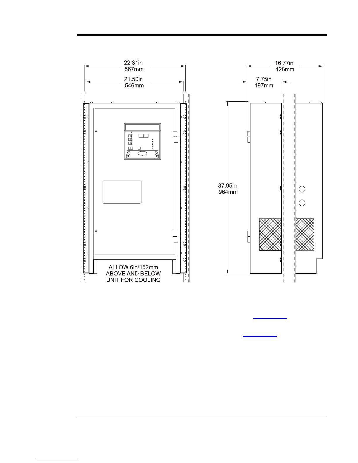
1. Refer to the outline drawings in Appendix C, starting on Page 66, for the
overall footprint of the Style-5018, Style-5030, and Style-163 enclosures.
2. Be conscious of planned ac input and dc output wiring to the AT30,
selecting conduit entrances carefully. Note the standard pre-fab conduit
knockouts located on the sides (and sometimes tops) of the enclosures.
3. The location:
• Should be free of drips and splatter. If falling particles and liquids are a
problem, install NEMA-2 type drip shield accessory (EI0191-0#). For
kit availability, see ordering information in Appendix B on page 65.
• Should be between 0 and 122 °F / -18 and 50 °C, with relative humidity
between 5% and 95% non-condensing.
• Must be free of flammable or explosive materials.
4. Maintain at least 6in / 152mm of free air on all vented surfaces for cooling.
5. Allow at least 36in / 914mm front clearance for access to the AT30 for
operation and maintenance.
PROCEDURE (Style-5018)
1. Install four (4) 0.25in / 6.4mm anchor bolts into the floor, per the mounting
dimensions featured in the outline drawing (JE5085-00).
2. Carefully lift the AT30 above the anchor bolts using the methods described
in Section 1.4. Guide the enclosure onto the floor bolt pattern and lower it
into place.
3. Add appropriate mounting hardware onto the floor-mounting anchor bolts
and tighten securely.

INSTALLING THE AT30
5
PROCEDURE (Style-5030)
1. Install four (4) 0.375 / 9.5mm or 0.5in/12.7mm anchor bolts into the floor,
per the mounting dimensions featured in the outline drawing (JE5086-00).
2. Carefully lift the AT30 above the anchor bolts using the methods described
in Section 1.4. Guide the enclosure onto the floor bolt pattern and lower it
into place.
3. Add appropriate mounting hardware onto the floor-mounting anchor bolts
and tighten securely.
PROCEDURE (Style-163 / Style-198)
1. Install four (4) 0.5in/12.7mm anchor bolts into the floor, per the mounting
dimensions featured in the outline drawings (JE5095-00 / JE5096-00).
2. Carefully lift the AT30 above the anchor bolts using the methods described
in Section 1.4. Guide the enclosure onto the floor bolt pattern and lower it
into place.
3. Add appropriate mounting hardware onto the floor-mounting anchor bolts
and tighten securely.
GRAPHICS - STANDARD NEMA-1 TYPE AT30 ENCLOSURES
Style-5018
see outline drawing
JE5085-00
Style-5030
see outline drawing
JE5086-00
Style-163
see outline drawing
JE5095-00

INSTALLING THE AT30
6
1.5.2. Wall-Mounting the AT30 (Style-5018 enclosure only)
To install the AT30 onto a vertical surface, the standard Style-5018
enclosure does not need to be modified, but a special wall-mounting
accessory (EI5008-00) is required. For kit availability see ordering
information in Appendix B on page 65. The kit includes two (2)
mounting brackets, appropriate hardware, and Installation Instructions
(JA5063-00) for the wall-mounting procedure.
When wall-mounting the AT30, consider the following:
1. The wall must be strong enough to properly support the weight of the AT30
and the mounting brackets. Comprehensive weight data for the different
models is available in the AT30 product literature (JF5018-00). The
weight of your AT30 may be different from the literature value, depending
on supplied features, options, or accessories.
2. Be conscious of planned ac input and dc output wiring to the AT30,
selecting conduit entrances carefully. Note the standard pre-fab conduit
knockouts located on the sides the Style-5018 enclosure.
3. The location:
• Should be free of drips and splatter. If falling particles and liquids are a
problem, install NEMA-2 type drip shield accessory (EI0191-0#). For
kit availability, see ordering information in Appendix B on page 65.
• Should be between 0 and 122 °F / -18 and 50 °C, with relative humidity
between 5% and 95% non-condensing.
• Must be free of flammable or explosive materials.
4. Maintain at least 6in / 152mm of free air on all vented surfaces for cooling.
5. Allow at least 36in / 914mm front clearance for access to the AT30 for
operation and maintenance.
PROCEDURE
1. Install eight (8) 0.25in / 6.4mm anchor
bolts (not supplied) rated to support the
AT30 weight plus a safety factor of at
least two (2) times, into the wall.
2. Mount the triangular brackets to the wall.
3. Carefully lift the Style-5018 enclosure
onto the mounted triangular brackets.
4. Use the supplied 0.25in / 6.4mm hardware
to mount the enclosure to the wall-
mounting brackets and tighten securely.
5. Refer to the graphics on the opposite page
for the AT30 Style-5018 wall-mounting
pattern and enclosure footprint.
6. Dimensions are in/mm.

INSTALLING THE AT30
7
GRAPHICS - WALL-MOUNTING THE AT30
NOTES
1. Refer to the Style-5018 enclosure outline drawing (JE5085-00) in
Appendix C on Page 66 for overall size, mounting dimensions, and cabinet
specifications.
2. See Installation Instructions (JA5063-00) for the special Style-5018 wall-
mounting procedure.

INSTALLING THE AT30
8
1.5.3. Rack-Mounting the AT30 (Style-5018 enclosure only)
Smaller AT30s can be installed in 23-24in /584-610mm relay racks with
standard EIA hole spacing. The Style-5018 enclosure does not need to be
modified for rack mounting, but a special kit (EI0193-0#) is required.
For kit availability see the ordering information in Appendix B on page
65. The kit includes two (2) mounting brackets, hardware, and
Installation Instructions (JA0091-03) for the rack-mounting procedure.
When rack-mounting the AT30, consider the following:
1. The relay rack must be strong enough to properly support the weight of the
AT30. Comprehensive weight data for the different models is available in
the AT30 product literature (JF5018-00). The weight of your AT30 may
be different from the literature value, depending on supplied features,
options, or accessories.
2. Be conscious of planned ac input and dc output wiring to the AT30,
selecting conduit entrances carefully. Note the standard pre-fab conduit
knockouts located on the sides of the enclosures. Ensure that planned
conduit is accessible after the AT30 is rack-mounted.
3. The location:
• Should be free of drips and splatter. If falling particles and liquids are a
problem, install a NEMA-2 type drip shield accessory (EI0191-02). For
kit availability, see ordering information in Appendix B on page 65.
• Should be between 0 and 122 °F / -18 and 50 °C, with relative humidity
between 5% and 95% non-condensing.
• Must be free of flammable or explosive materials.
4. Maintain at least 6in / 152mm of free air on all vented surfaces for cooling.
5. Allow at least 36in / 914mm front clearance for access to the AT30 for
operation and maintenance.
PROCEDURE
1. Attach the two (2) relay rack-mounting brackets
to the sides of the Style-5018 enclosure, using
the four (4) small pre-fab knockouts as guides.
2. Mount the brackets to the AT30, using the
supplied 0.25in / 6.4mm hardware and tighten
securely.
3. Using a scissor lift, guide the AT30 into the
front face of the 23in / 584mm EIA relay rack.
4. Adjust the height of the AT10 and mount in
place using appropiate hardware (not supplied).
5. Refer to the graphics on the opposite page for
the rack-mounted enclosure footprint.
INSTALLING THE AT30
9
GRAPHICS - RACK-MOUNTING THE AT30
NOTES
1. Rack-mount AT30 Style-5018 enclosures are installed from the front.
2. Refer to the Style-5018 enclosure outline drawing (JE5085-00) in
Appendix C on Page 66 for overall size and cabinet specifications.
3. Refer to the detailed Installation Instructions (JA0091-03) supplied with
the kit for the special rack-mounting procedure.

INSTALLING THE AT30
10
1.6. CHANGING THE TRANSFORMER TAPS
AT30s are normally designed for a single ac input supply voltage. Verify
the ac voltage listed on the data nameplate decal, and the ..CAUTION..
tag attached to the ac input circuit breaker (CB1). The AT30 ac input
transformer (T1) is designed with a voltage tolerance of +10% to -12%.
!WARNING
If your particular site ac supply voltage does not match your AT30
ac input requirements, you may need to change the ac input circuit
breaker (and/or fuses) and the input surge suppressors. In
addition, you must replace (or rewire) the ac input power isolation
transformer (T1) as described below.
Failure to use properly rated components may damage the AT30.
If your AT10.1 was supplied with the 480 Vac 60Hz ac input feature, the
transformer will only accept the listed voltage.
NOTICE
Do not attempt to rewire the 480Vac transformer. If a different ac
input voltage feature for the AT30 is desired, please contact your sales
representative for ordering replacement parts (T1, CB1, VR2-VR5).
If your AT30 was supplied with one of the following ac input voltage
features, the transformer is re-tappable:
• 208 or 240Vac 60Hz
• 220 or 240Vac 50/60Hz
• 380 or 416Vac 50/60Hz
• 550 or 600Vac 50/60Hz
Before you connect ac power to the AT30, inspect the primary wiring of
the ac input transformer (T1). Make sure it is "tapped" for the desired ac
input supply voltage.
NOTICE
Before starting work, disconnect and lock out all external ac and
dc power sources to the AT30. Merely turning off (opening) the
front panel ac and dc circuit breakers (CB1/CB2) is not sufficient
to eliminate live voltages inside the enclosure. Verify that no
voltages are present inside the AT30, using a voltmeter at the
ac terminals TB1-L1, TB1-L2 & TB1-L3, the dc terminals TB1(+)
& TB1(-), the dc remote sense terminals, and any external
wiring to alarm relay contacts.

INSTALLING THE AT30
11
PROCEDURE
1. See Section 3.5 for necessary steps to follow when accessing internal
components within the AT30.
2. Shut down the AT30 and verify that no internal voltages are present.
3. Refer to the images below and identify the three (3) primary "taps" (T1-H1,
T1-H2 & T1-H3) of the power isolation transformer.
AT30 THREE PHASE ISOLATION TRANSFORMER
(excludes 480 Vac non-tappable variant)
TOP VIEW LAYOUT (T1) SCHEMATIC (T1)
4. Inside the AT30, inspect the transformer wiring, and identify the three (3)
jumpers on the primary-side wire "taps" (T1-H1/H2/H3).
5. Change the jumpers on the primary-side taps as needed per the table below.
jumper setting
208 or 220 or 380 or 550 Vac jumper setting
240 or 416 or 600 Vac
H1, H2 & H3 set to "1" H1, H2 & H3 set to "2"
6. Check your work, making sure no exposed wiring is touching ground.
7. Always use all three (3) jumpers, and make sure all connections are tight.
8. Restart the AT30 using the startup procedure in Section 2.1.
9. For more information, see the schematics & wiring diagrams in Appendix C.
10. Contact the factory for a new data nameplate with revised ac input values.
11. For a list of maximum ac input current values, refer to standard (DC5016-00).

INSTALLING THE AT30
12
1.7. MAKING THE AC INPUT CONNECTIONS
!WARNING
The A30 is a commercial product, and not intended for use in a residential
environment, or to be powered by low-voltage public mains.
It is the responsibility of the installer of the AT30 to provide suitable ac
supply wiring. Wiring must be approved for use in the country in which
the AT30 is installed. When selecting wire sizes, consult the data
nameplate decal affixed to the front panel of the AT30 for maximum
voltage and current requirements. The AT30 must also be grounded in
accordance with the electrical rules of the country where installed.
Follow these steps to connect ac power to the AT30:
1. Confirm that the AT30 main power transformer (T1) is properly jumpered for
your ac input supply voltage. See Section 1.6 for details.
2. Use a branch circuit breaker or fused disconnect switch upstream from the
AT30. This device should have lockout capability so that the ac input supply to
the AT30 can be de-energized for charger maintenance. A time delay circuit
breaker or slow-blow fuse is recommended.
3. Size the branch circuit breaker or fused disconnect switch for the maximum ac
input current of the AT30. This rating is listed on the left-hand side of the
AT30 data nameplate. For a comprehensive list of these maximum ac input
values, access standard (DC5016-00).
NOTICE
If your AT30 is wired for 480 Vac input, and is equipped with the standard
AIC ac input circuit breaker (no ac fuses), you need a feeder breaker or
fuse rated to interrupt the short-circuit current of your ac supply.
4. Size ac input wiring per the National Electric Code (NEC) and local codes for
the trip rating of the branch circuit breaker or fused disconnect switch.
5. Do not run external ac input power wiring through the same conduit of the
AT30 enclosure as external dc output power wiring.
6. All site requirements of your facility take precedence over these instructions.
PROCEDURE
1. Remove the Plexiglas safety shield (if supplied).
2. Run the ac input supply wiring into the AT30, ending at terminals TB1-L1,
TB1-L2, TB1-L3, and TB1-GND on the I/O panel board.
3. The AT30 features four (4) CU-AL compression lugs on the ac input terminals.
• Style-5018 and Style-5030 enclosure ac lugs accept #14 - 1/0 AWG wire
• Style-163 and Style-198 enclosure ac lugs accept #6 AWG - 350 MCM wire
4. Strip 0.50in / 13mm from the insulation of the incoming ac input supply wiring.
5. Connect the wires to the appropriate ac lugs as shown on the next page.
6. Using proper tools, securely tighten the compression screws on the ac lugs to
proper torque specifications.
7. Check all connections and reinstall the Plexiglas safety shield (if supplied).
INSTALLING THE AT30
13
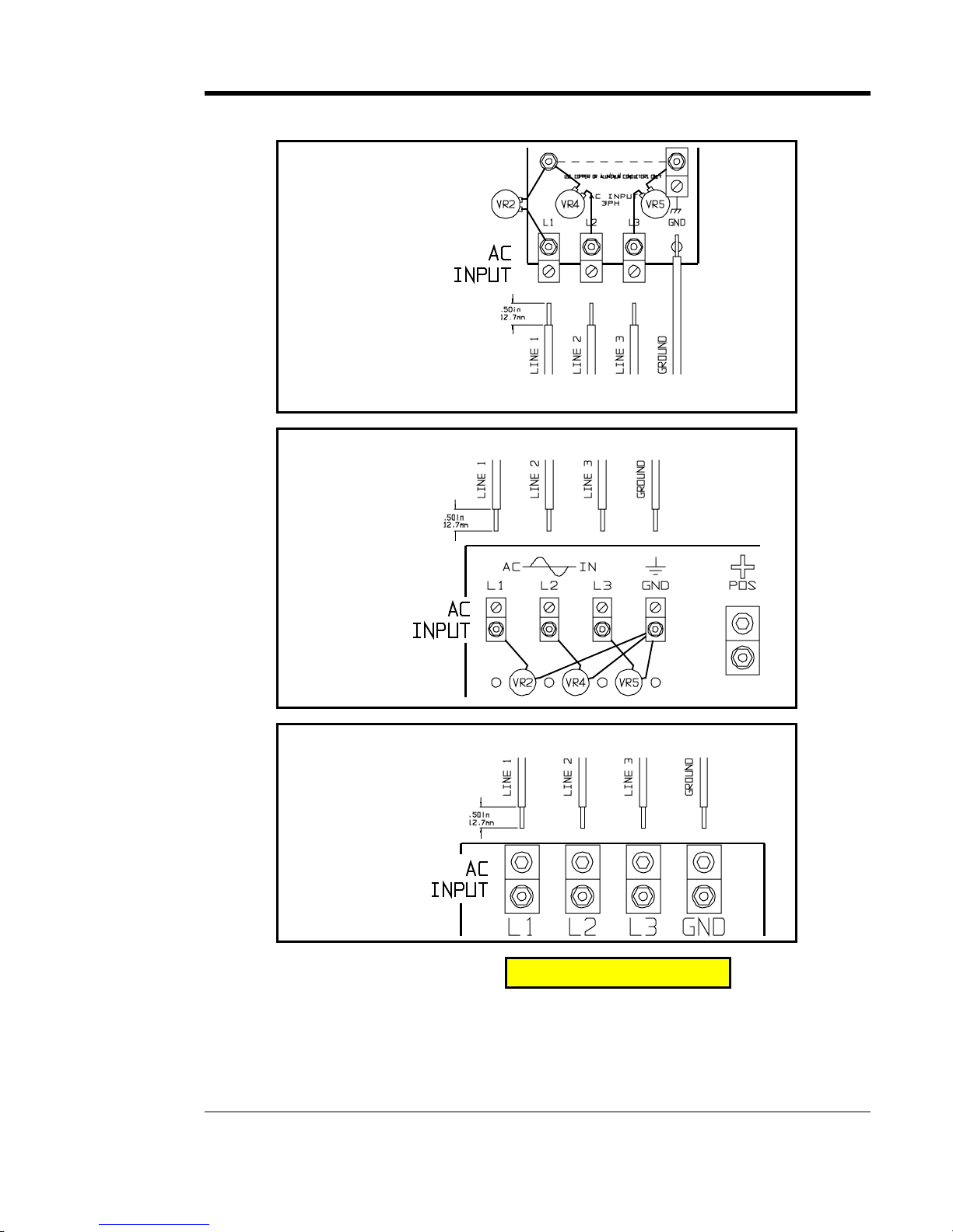
MAKING THE AC INPUT CONNECTIONS - GRAPHICS
Style-5018
I/O Terminal
Board (TB1)
Detail
user-supplied ac input wiring
user-supplied ac input wiring
Style-5030
I/O Terminal
Board (TB1)
Detail
user-supplied ac input wiring
Style-163
I/O Terminal
Board (TB1)
Detail
NOTES !CAUTION
1. The ac input terminal hardware fastens other components mounted to the I/O
panel (TB1-L#). Be careful not to disconect any other component leads.
2. Conduit must be properly grounded, and in compliance with the nationalwiring
rules of the country where installed.
3. Use copper or aluminum conductors only.

INSTALLING THE AT30
14
1.8. MAKING THE DC OUTPUT CONNECTIONS
It is the responsibility of the installer of the AT30 to provide suitable dc
output, battery, and dc load wiring. Follow these steps to connect the
battery to the AT30:
1. Size the dc wiring to minimize voltage drop. The acceptable wire size
depends on your installation. As a guideline, the voltage drop should not
exceed 1% of nominal output voltage at full current.
2. Size the dc output wiring per your battery manufacturer's specifications and
local codes for the rating of the batteries and/or load.
3. The AT30 is factory wired to regulate the output voltage at the output
terminals. If the total voltage drop is greater than 1% (e.g., 1.3V for a 130
Vdc system), remote sense wiring is recommended, see Section 1.9.
4. Do not run the external dc power wiring through the same conduit of the
AT30 enclosure as the external ac power wiring.
5. All specific requirements of your facility take precedence over these
instructions.
PROCEDURE
1. Use a dc disconnect switch or circuit breaker between the AT30 and the dc
bus. This device should have lockout capability to allow the AT30 to be
disconnected from the dc bus for maintenance.
2. Remove the Plexiglas safety shield (if supplied).
3. Run the dc wiring to terminals TB1(+) and TB1(-) on the I/O panel board in
the enclosure. CU-AL Compression lugs are supplied for your convenience.
• Style-5018 enclosure dc output lugs accept #14 - 1/0 AWG wire
• Style-5030/163 enclosure dc output lugs accept #6 AWG - 350 MCM wire
4. Strip the insulation 0.5in / 12.7mm on the incoming ac wires and connect the
wires to the appropriate dc lugs as shown on the next page.
5. Using proper tools, securely tighten the compression screws on the lugs to
proper torque values.
6. Check all connections and reinstall the Plexiglas safety shield (if supplied).
!CAUTION
NOTES
1. The dc output terminal hardware fastens other components mounted to the
I/O panel. Be careful not to disconect any other component leads.
2. Always use a proper ground.
3. Use copper or aluminum conductors only.
4. Refer to images on the following page for I/O panel layout.

INSTALLING THE AT30
15
MAKING THE DC OUTPUT CONNECTIONS - GRAPHICS
user-supplied dc output wiring
Style-5018
I/O Terminal
Board (TB1)
Detail
user-supplied dc output wiring
Style-5030
I/O Terminal
Board (TB1)
Detail
Style-163
I/O Terminal
Board (TB1)
Detail
user-supplied dc output wiring
INSTALLING THE AT30
16
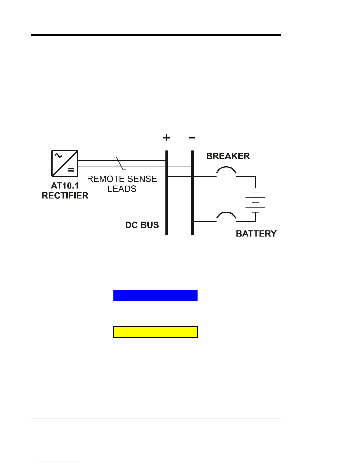
1.9. WIRING THE AT30 FOR REMOTE SENSING
You can wire the AT30 to regulate the output voltage at the battery
terminals, instead of at the charger output terminals (TB1+/-). Remote
sensing provides the following:
1. Compensates for voltage drop in the dc wiring between the AT30 and the
battery.
2. Directly monitors the battery or dc bus voltage. The front panel meter
displays the actual voltage on the battery or dc bus.
SCHEMATIC
You wire the AT30 for remote sensing by installing twisted pair cabling
from the AT30 remote sense terminals to the battery terminals. The AT30
control circuitry then measures the dc voltage at the battery terminals, and
controls the output of the charger to maintain the battery voltage at the
desired float or equalize voltage.
NOTICE
If the remote sense wiring fails, the AT30 detects the fault, and
displays E 06 on the front panel meter. See Section 3.2 for details.
!CAUTION
The AT30 cannot protect against short circuits in the remote sense
wiring. You should install a 1.0A fuse at the battery or dc bus end of
the remote sense cable.
PROCEDURE
1. De-energize and lock out all ac and dc voltages within the AT30 enclosure.
Check with a voltmeter.
2. Remove safety shield (if supplied).
3. Remove the two (2) dc output CU-AL compression lugs.
Other manuals for AT30 SERIES
1
Table of contents
Other HindlePower Batteries Charger manuals

HindlePower
HindlePower SCRF series Training manual

HindlePower
HindlePower ATevo Series Instruction Manual

HindlePower
HindlePower UMC Series Training manual

HindlePower
HindlePower ATevo Series User manual

HindlePower
HindlePower ATevo Series User manual

HindlePower
HindlePower AT10.1 series User manual

HindlePower
HindlePower SCRF series Training manual

HindlePower
HindlePower SCR series User manual

HindlePower
HindlePower AT30 SERIES Training manual

HindlePower
HindlePower ATevo Series User manual


LG Standart manual")


