HindlePower UMC Series Training manual
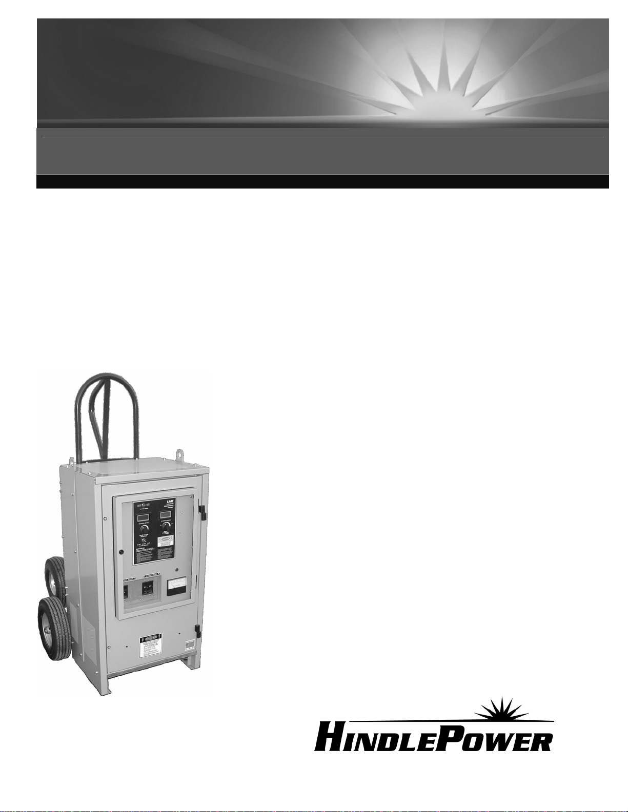
UMC SERIES
Operating and Service Instructions
UNIVERSAL MAINTENANCE CHARGER
120/208/240/480 Vac SINGLE PHASE INPUT
24/48/130 Vdc ADJUSTABLE OUTPUT
JA5041-01

QUICK STARTUP
TURN OFF ALL POWER AND TURN OFF UMC'S INPUT & OUTPUT CIRCUIT BREAKERS (CB1 & CB2)
1. Move input jumpers on I/O panel to match the required input voltage. See connection chart on wiring diagram
inside enclosure.
2. Connect the input terminals (TB1-L1/L2) to available ac power.
3. See table/nameplate for input currents required.
4. If reduced input/output currents are required, adjust the Output Current Limit to minimum (counter-clockwise).
5. Connect cables to the dc bus or battery (properly rate wire size for the current required).
6. Select output voltage rating 130V, 48V or 24V using the Voltage Selector Switch on front panel.
7. Set Voltage Check switch to Charger Voltage (left position).
8. Turn on ac source and the ac input circuit breaker and adjust output voltage to desired set point. DO NOT
turn on the dc output circuit breaker at this point. Monitor the output voltage on the dc voltmeter, and adjust
the Output Voltage control slowly to the desired value. It may take several seconds for the output voltage to
settle to the desired voltage.
9. Set Voltage Check switch to Battery Voltage (right position). Check for proper polarity and voltage.
10. Turn on the dc output circuit breaker; current will be displayed on the ac and dc ammeters.
11. Increase Current Limit Adjustment clockwise to obtain the desired output current. Monitor the ac input current
on the ac ammeter in the lower right corner of the front panel. Do not allow the input current to exceed 66
Aac, as shown in the table below.
DC OUTPUT CURRENT 10A 20A 30A 55A
AC INPUT VOLTAGE
AC INPUT CURRENT
120V 25A 48A 66A **
208V 17A 24A 44A 60A
240V 15A 22A 35A 51A
480V 8A 15A 17A 26A
INPUT CURRENT TABLE
** Full output current at 120Vac input will cause the input current to exceed breaker rating.
IMPORTANT OPERATION NOTES
The battery charger’s output voltage is capable of adjustment over 145Vdc. The output current limit needs to
be reduced when operating at levels above 145Vdc.
Adjust the Output Current Limit of 50A units to 40A.
Adjust the Output Current Limit of 25A units to 22A.
...!WARNING... WORKING WITH BATTERIES
Some reasons why someone would wish to overcharge a battery bank is when the battery’s temperature is
very low, or the electrolyte has stratified. Once charging takes place the batteries may start to heat, or electrolyte
mixes and the batteries will start to show signs of gassing. The charger WILL need to be readjusted to a lower output
voltage to prevent damage to the batteries.
NEVER LEAVE BATTERIES UNATTENDED DURING THIS KIND OF CHARGING!
NEVER LET THE INTERNAL PLATES OF THE BATTERY TO BE EXPOSED TO AIR!
FOLLOW ALL RECOMMENDED PROCEDURES PROVIDED BY THE BATTERY MANUFACTURER!
Battery banks greater than 130V can be charged. Connect to a portion of the bank at a time and move to the next
portion until all the batteries are charged. This should only be done if there is no or little standing load while charging.
SPECIFICATIONS
REGULATION: + or - 0.5% no-load to full-load
REGULATION: + or - 0.5% for + or - 10% AC line variation
REGULATION: + or - 1% for combined load, line & temperature variations
120-240Vac input protection 5 kAIC
480Vac input protection 200 kAIC
Ambient Temperature Range: 0 ºC to 40 ºC
Relative Humidity: up to 95% without condensation
Altitude: up to 1,000m above sea level

i
IMPORTANT SAFETY INSTRUCTIONS
1) Before using the battery charger, read all instructions and cautionary markings on:
A) battery charger, B) battery, C) equipment connected to charger and battery
2) This manual contains important safety and operating instructions, and therefore should be filed for
easy access.
3) Do not touch any uninsulated parts of the battery charger, especially the input and output
connections, as there is the possibility of electric shock.
4) During normal operation, batteries may produce explosive gas. NEVER smoke, use an open flame,
or create arcs in the vicinity of the battery charger or battery.
5) Maintain at least 1ft (0.3m) clearance from all obstructions on all sides of the battery charger.
6) Keep area in front of battery charger clear for at least 4ft (1.3m).
7) Connect or disconnect the battery only when the battery charger is off to prevent arcing or burning.
8) De-energize all ac and dc inputs to the battery charger before servicing.
9) Do not operate the battery charger if it has been damaged in any way. Refer to qualified service
personnel only.
10) Do not disassemble the battery charger. Only qualified service personnel should attempt repairs.
Incorrect reassembly may result in explosion, electrical shock, or fire.
11) Do not install the battery charger outdoors, or in wet or damp locations unless specifically ordered
for that environment.
12) Remove all jewelry, watches, rings, etc. before proceeding with installation.
13) Check your ac input current resources before choosing input power and installing input cables.
READ AND FOLLOW
ALL SAFETY INSTRUCTIONS

ii
TABLE OF CONTENTS
Page No.
SECTION I
•Quick Startup........................................................................................................... Inside Front Cover
•Notes And Warnings...............................................................................................Inside Front Cover
•Specifications .......................................................................................................... Inside Front Cover
•Important Safety Instructions............................................................................................................... i
•Table Of Contents (this page) ............................................................................................................. ii
SECTION II - Installation And Operation
•Battery Safety Notice ...........................................................................................................................1
•Application...........................................................................................................................................1
•Installation............................................................................................................................................2
•Powering Up.........................................................................................................................................2
•Maintenance .........................................................................................................................................3
•Internal Protection................................................................................................................................3
•Descriptions Of Component Operation................................................................................................3
SECTION III - Troubleshooting
•...!CAUTION... Notice.....................................................................................................................4
•Quick First Checks...............................................................................................................................4
•Troubleshooting Procedure ..................................................................................................................4
•Testing Of Components....................................................................................................................5-6
SECTION IV - Replacement Components
•Instructions...........................................................................................................................................6
SECTION V - Document Control Information
•Manual Revision...................................................................................................................................7
•Document Information .........................................................................................................................7
•Online Availability Note......................................................................................................................7
SECTION VI - Parts Data Package Report
•Parts Data Package Report: UMC 10-25Adc (BB0443-00)...................................supplemental insert
or
•Parts Data Package Report: UMC 10-50Adc (BB0443-01)...................................supplemental insert
SECTION VII - Supplemental Drawings
•Universal Maintenance Charger (UMC) Drawing List / Data Nameplate Detail...............................JE5035-##
•Universal Maintenance Charger (UMC) Outline Drawing NEMA-1 Style-5018 Enclosure .............JE5036-##
•Universal Maintenance Charger (UMC) Internal Component Layout Drawing St-5018 Encl...........JE5037-##
•Universal Maintenance Charger (UMC) Instrument Panel Detail......................................................JE5038-##
•Universal Maintenance Charger (UMC) Schematic...........................................................................JE5039-##
•Universal Maintenance Charger (UMC) Connection Diagram ..........................................................JE5040-##

1
UNIVERSAL MAINTENANCE CHARGER (UMC)
INSTALLATION AND OPERATION
1. BATTERY SAFETY NOTICE
...!WARNING... BATTERIES CONTAIN DANGEROUS CHEMICALS AND
PRODUCE HYDROGEN GAS DURING CHARGING! THIS EQUIPMENT
(UMC) SSHOULD BE CONNECTED AND DISCONNECTED WITH CARE.
ALWAYS OPEN THE DC BREAKER (CB2) BEFORE CONNECTING OR
DISCONNECTING THE BATTERIES, SO THAT NO SPARK OR ARC WILL
OCCUR AT THE BATTERY TERMINALS.
2. APPLICATION
The Universal Maintenance Charger (UMC) is a standby constant voltage battery charger designed to provide:
1) temporary replacement for a battery charger that needs repair or refit
2) charging for a new installation of a battery bank waiting for charger installation, or batteries in storage
3) emergency replacement for a catastrophic failure of a dc bus
FEATURES
•Input voltage connections are available for 120/208/240/480Vac single phase 60Hz
(input current control for temporary feeds that may lack charger’s full current capability)
•The output voltage is designed to charge a battery bank of 24V, 48V or 130V depending on setting.
•The voltage output adjustment is broad enough to charge any cell combination from 20V to 145V
•Output voltage and current displayed through 1% digital meters (M1/M2)
•AC input circuit breaker (CB1)
•AC input ammeter (M3)
•DC output circuit breaker (CB2)
•Charger/battery voltage switch (SW2) to check dc voltage compatibility prior to connection
•No dc fuses to clear if battery connection is incorrect or setting is incorrect
•Front panel adjustable current limit to reduce input current and charge current
•Built-in mobile cart and lifting eyes for transportation
•Covered controls for maximum protection during transport or harsh environments
CONTROLS
•AC AMMETER (M3): 0-50Aac or 0-100Aac - 2% needle-indicating analog meter
•DC VOLTMETER (M2): 0-200Vdc 1% digital meter
•DC AMMETER (M1): 0-100Adc 1% digital meter
•DC OUTPUT VOLTAGE ADJUSTMENT (R5): 10-turn control for fine voltage adjustment
•DC OUTPUT CURRENT LIMIT CONTROL (R12): 1-turn current limit control
•DC VOLTAGE SELECTOR SWITCH (SW1): Coarse voltage selection for 24, 48 or 130V
APPLICATION CONSIDERATIONS
Although the battery charger is designed to operate with a battery, it can be connected to loads such as dc-to-dc power
supplies or inverters. Ripple content is designed to be below 200 mVac rms, without the battery connected, on resistive load.
The battery charger is designed to connect to a high capacitive load like a battery. It is wise to consider the effect when large
inductive loads are attached, like a dc motor without the battery. The response to these loads is a reduction of output voltage with
a recovery time in seconds. Once the load is stabilized the battery charger will support most loads with little problem.
Conversely when loads are shed, there may be a voltage rise in the output due to the large filter stage. Care needs to be taken
when the loads attached are sensitive to voltages 5% above the charger’s set voltage level.
This charger can be used on any number of lead-acid, nickel-cadmium, or nickel-iron cells, as long as the desired
voltages are within the UMC range. Batteries are not alike so check with the battery manufacture’s charging procedures and
practices. Pay attention to what the batteries are doing during the charging process. Some battery types may produce more gas
(hydrogen and oxygen) and need to be monitored for loss of water. Never leave the charger unattended for long periods of time.
The battery charger can be installed in an environment more severe then specifications allow. Reduce the output current
to 60% of the charger’s rated output for 50 ºC ambient or 3,300 ft (1,000m) above sea level.
Table of contents
Other HindlePower Batteries Charger manuals

HindlePower
HindlePower ATevo Series User manual

HindlePower
HindlePower SCR series User manual

HindlePower
HindlePower SCRF series Training manual

HindlePower
HindlePower SCRF series Training manual

HindlePower
HindlePower AT10.1 series User manual

HindlePower
HindlePower ATevo Series User manual

HindlePower
HindlePower ATevo Series Instruction Manual

HindlePower
HindlePower ATevo Series User manual

HindlePower
HindlePower AT30 SERIES Training manual

HindlePower
HindlePower AT30 SERIES Training manual


