Hiniker DB-5245-1 User manual

HINIKER V-PLOW
DB-5245-1 STONE
HYDRAULIC UNIT
SERVICE MANUAL
DO NOT USE OR OPERATE THIS EQUIPMENT UNTIL THIS MANUAL
HAS BEEN READ AND THOROUGHLY UNDERSTOOD
PART NUMBER 25012796


TITLE
Introduction
POWER UNIT OPERATION
GENERAL
The hydraulic power unit consists of a 12 VDC
motor, a hydraulic pump rated at 1.9 GPM @
1600 PSI, and a valve body containing six nor-
mally closed electric solenoid valves and three
adjustable pressure relief valves. The uid sup-
ply line for the pump is submerged in a 2.5 quart
capacity reservoir and is ltered by a 149 micron
screen.
The valve body directs hydraulic uid to operate
six hydraulic circuits, raise, lower, angle left, an-
gle right, vee and scoop. The raise, angle, vee
and scoop circuits receive uid under pressure,
and the lower circuit does not, however, pressure
is generated as uid returns to the reservoir.
RAISE MODE OF OPERATION
Operating the Raise switch energizes the 12
VDC motor, the S5 solenoid valve and de-en-
ergizes the S6 solenoid valve. Hydraulic uid
under pressure is then directed through the S5
solenoid valve and a one way check valve (CV1)
to the lift cylinder.
Releasing the Raise switch de-energizes the
12 VDC motor and the S5 solenoid valve. The
one way check valve (CV1) maintains hydraulic
pressure in the lift cylinder.
The raise circuit is protected by a pressure relief
valve (SYSRV) set to relieve system pressure at
2250 PSI.. Typically, pressure is relieved when
the lift cylinder reaches the full up position.
LOWER MODE OF OPERATION
Operating the Lower switch energizes the S6 so-
lenoid valve, lowers the blade and establishes a
oat circuit. The oat circuit allows uid to enter
or exit the lift cylinder allowing the blade to fol-
low the contour of the ground.
ANGLE LEFT MODE OF OPERATION
Operating theAngle Left switch energizes the 12
VDC motor, the S2 solenoid valve and the S3
solenoid valve. Hydraulic uid under pressure is
then directed through the S2 solenoid valve to
the right wing cylinder. Hydraulic uid, not under
pressure, is directed from the left wing cylinder
through the S4 solenoid valve back to the reser-
voir as the cylinder retracts.
The right wing circuit is protected by a crossover
relief valve (RV2) set to relieve system pressure
at 2700 PSI. It is also protected by a retraction
relief (RV5) set at 3000 PSI.
ANGLE RIGHT MODE OF OPERATION
Operating the Angle Right switch energizes the
12 VDC motor, the S1 solenoid valve and the S4
solenoid valve. Hydraulic uid under pressure is
then directed through the S1 solenoid valve to
the left wing cylinder. Hydraulic uid, not under
pressure, is directed from the right wing cylinder
through the S2 solenoid valve back to the reser-
voir as the cylinder retracts.
The left wing circuit is protected by a crossover
relief valve (RV3) set to relieve system pressure
at 2700 PSI. Typically, pressure is relieved when
the left wing cylinder reaches its fully extended
position. It is also protected by a retraction relief
(RV4) set at 3000 PSI.
VEE MODE OF OPERATION
Operating the Vee switch energizes the 12 VDC
motor and the SI and S3 solenoids pumping uid
through hosesAand C to the rod end of the wing
cylinders. Fluid from the butt end of the cylinders
returns to the tank through hoses B and D and
valves S2 and S4
SCOOP MODE OF OPERATION
Operating the Scoop switch energizes the 12
VDC motor, the S2 solenoid valve and the S4
solenoid valve pumping uid through hoses B
and D to the butt end of the wing cylinders. Fluid
from the rod end of the cylinders returns to the
tank through hoses A and C and valves S1 and
S3

Power Unit - Hydraulic
POWER UNIT - SPX MODEL DB-5245-1
REF.
NO. PART
NUMBER DESCRIPTION QTY. REF.
NO. PART
NUMBER DESCRIPTION QTY.
1
2
3
4
5
6
7
8
9
10
11
12
13
14
15
16
17
18
25010734
950-001-327
25010332
25010244
25010221
25010334
25010214
25010236
25011654
25011667
25010544
25010992
25010230
25010337
25010746
25012736
25010330
25010518
PumpAssembly
Hex Head Cap Screw 5/16-24 x 3 Gr. 8
Inlet Plumbing Kit
Plumbing Elbow
Filter
Pump O-Ring Kit
Coupling
O-Ring
Release Valve Kit
Solenoid Coil
Cartridge Release Valve
O-Ring Kit
Motor 12V DC
Motor Brush Kit
Check Valve
Orice With O-Ring
Adjustable Relief Valve Kit
Adjustable Relief Valve O-Ring
1
2
1
1
1
1
1
1
2
6
2
1
1
1
1
1
1
1
19
20
21
22
23
24
25
26
27
28
29
30
31
32
33
34
35
25010738
950-004-071
25010436
25010217
25010220
25010762
25012678
25010985
950-004-095
952-004-080
25011525
25010935
25012737
25010745
25012673
952-001-001
951-001-003
Plastic Tank
Machine Screw #12-24 x 1/2 Hex Washer Head
Decal - Fill Line
Plastic Breather
Plumbing Magnet
Manifold O-Ring Kit
Relief Valve
Crossover Relief Valve
Socket Head Cap Screw 1/4-20 x 2 1/2
Lock Washer 1/4 Inch
Spool Valve
Return Tube
Return Tube
Return Tube Filter
Ground Stud 1/4-20
Lock Washer 1/4 Inch
Hex Nut 1/4-20
1
4
1
1
1
1
2
2
4
4
2
1
1
2
1
1
1
DWG. NO. 6526A
25012648 Power Unit - SPX Model DB-5245-1

Power Unit Hydraulic Circuit Diagram
DWG NO. 6459

Introduction
V-Plow Power Unit
DWG NO. 6457A

TITLE
TABLE OF CONTENTS
25012796 3/10 Manual/25012796
Troubleshooting Procedures....................................................................................................... 2
V-Plow Will Not Raise.................................................................................................................. 3
V-Plow Lifts Slowly ...................................................................................................................... 4
V-Plow Will Not Stay Up.............................................................................................................. 5
V-Plow Will Not Lower................................................................................................................. 6
Left Wing Will Not Extend ........................................................................................................... 7
Right Wing Will Not Extend......................................................................................................... 8
Left Wing Will Not Stay Extended............................................................................................... 9
Right Wing Will Not Stay Extended.......................................................................................... 10
Left Wing Will Not Retract..........................................................................................................11
Right Wing Will Not Retract ...................................................................................................... 12
DC Motor Removal and Replacement...................................................................................... 13
DC Motor Brush Replacement.................................................................................................. 14
Check Valve Removal, Cleaning & Replacement (CV1) ........................................................ 15
Relief Valve Removal, Cleaning & Replacement .................................................................... 16
System Relief Valve Removal, Cleaning & Replacement....................................................... 17
Solenoid Valve Removal, Cleaning and Replacement.......................................................18-19
Spool Valve Removal, Cleaning and Replacement..................................................................... 20
Valve Block Removal, Cleaning and Replacement................................................................. 21
Hydraulic Pump Removal, Cleaning and Replacement.....................................................22-23
Flow Control Valve Removal, Cleaning and Replacement..................................................... 24
System Relief Valve Testing and Adjustment.......................................................................... 25
DC Motor Current Draw (Full Load).......................................................................................... 26
DC Motor Current Draw (No Load)........................................................................................... 27
Solenoid Test ............................................................................................................................. 28
Relief Valve Testing and Adjustment ....................................................................................... 29
Hydraulic Pump Test.................................................................................................................... 30
Table of Contents 1

TITLE
TROUBLESHOOTING PROCEDURES
INTRODUCTION
This section is designed to help you troubleshoot
the hydraulic system on the Hiniker V-Plow.
Each procedure consists of a detailed problem
description followed by a step-by-step ow chart
that will direct you to do certain service or test
procedures. If each service or test procedure is
done step-by-step in the order given, the prob-
lem can usually be corrected.
INITIAL INSPECTION
1. Make sure vehicle is in park and parking
brake is set.
2. Retract wings fully and lower plow to the
ground before servicing any part of the hy-
draulic or electrical systems.
3. Inspect all wiring harness connectors for:
A. Corrosion or dirt in and/or on Pins and
Sockets.
B.Damagedor missingPinsand/or Sockets.
C. Full engagement of Pins into respective
Sockets.
4. Check Ground.
A.Makesurebatterygroundto vehicleframe
is clean, corrosion free and tight.
B. Make sure that ground connections from
the Snow Plow harness to vehicle frame
or battery are clean, corrosion free and
tight.
5. Verify the correct hydraulic uid is being
used in unit and make sure oil level is to “Fill
Line” when the plow is on the ground and
the wings retracted.
6. Check all hoses and cylinders for proper
condition and leaks.
7. Make sure battery is charged and charging
system is in good condition.
8. Check 10 AMP fuse located on the Under-
hood Wiring Harness. Replace if bad.
9. Make sure joystick controller is connected in
the cab and turned on.
2 Troubleshooting

TITLE
V-Plow Will Not Raise 3
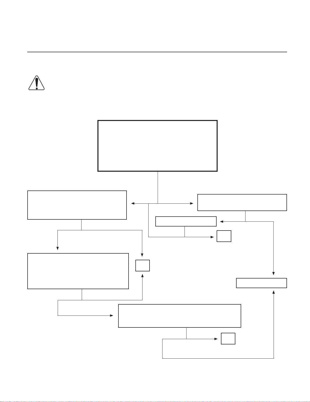
V-PLOW WILL NOT RAISE
Perform all initial inspections and checks listed on page 2 before beginning test procedure.
WARNING: Always retract wings fully, lower the plow to the ground and relieve pressure
before removing any ttings, hoses or caps. Allow the system to cool down before drain-
ing oil or handling system components. Serious burns can result from contact with hot
oil. FAILURE TO HEED CAN RESULT IN SERIOUS INJURY OR DEATH.
V-PLOW WILL NOT RAISE
ALL OTHER FUNCTIONS ARE NORMAL.
DOES PUMP MOTOR RUN?
Perform Solenoid Valve Test to S5 Solenoid
Valve. Repair or replace as necessary.
See page 28.
Does V-Plow raise?
Refer to electrical troubleshooting.
Does pump motor run?
Turn ignition switch on and momentarily ac-
tivate the RAISE switch on the joystick con-
trol box to ensure that the FLOAT mode is
OFF. Check S6 Solenoid Valve for magne-
tism by loosely holding metal end of screw-
driver within 1/8” of the nut end of the S6
Solenoid Valve Coil.
Is screwdriver attracted to nut end of coil?
Remove, inspect and clean System Relief
Valve. Repair or replace as necessary. See
page 17. Reinstall and adjust.
See page 25. Does V-Plow raise?
Remove, inspect and clean S6 Solenoid
Valve. See page 18-19. Repair or replace
as necessary. Does V-Plow raise?
Check ttings and lift cylinder hose for ob-
structions. Remove lift cylinder and drain
oil. Check for a frozen/binding cylinder by
manually compressing and extending the
cylinder. Repair or replace as necessary.
Does V-Plow raise?
Call Hiniker Service Does V-Plow Raise?
Call Hiniker Service
Yes No
No Yes End
No Yes
No Yes End
No Yes End
YesNo End
YesNo
End
YesNo

TITLE
V-PLOW LIFTS SLOWLY
Perform all initial inspections and checks listed on page 2 before beginning test procedure.
WARNING: Always retract wings fully, lower the plow to the ground and relieve pressure
before removing any ttings, hoses or caps. Allow the system to cool down before drain-
ing oil or handling system components. Serious burns can result from contact with hot
oil. FAILURE TO HEED CAN RESULT IN SERIOUS INJURY OR DEATH.
V-PLOW LIFTS SLOWLY
ALL OTHER FUNCTIONS ARE NORMAL.
Remove, inspect and clean System Relief Valve.
See page 17.
Adjust pressure. See page 25.
DOES V-PLOW LIFT FULLY UP IN APPROXIMATELY 2 SECONDS?
Remove, inspect and clean S5 Solenoid
Valve See page 18-19.
Repair or replace as necessary. Does V-
Plow lift fully up in approximately 2 sec-
onds?
Check ttings and lift cylinder hose for ob-
structions. Remove, lift cylinder and drain
oil. Check for a binding cylinder by manu-
ally compressing and extending the cylin-
der. Repair or replace as necessary. Does
V-Plow lift fully up in approximately 2 sec-
onds?
YesNo
YesNo End
Yes
No
Note: Until pump system warms, slow functioning of the V-Plow will occur in extremely cold tempera-
tures unless a high quality oil that is appropriate for the temperatures in which you will be plow-
ing snow is used. See chart below.
Note: Ensure vehicle battery is fully charged and alternator output is 13.6 Volts minimum with engine
running and no accessories on.
End
Call Hiniker Service DWG NO. 3066
4 V-Plow Lifts Slowly

TITLE
V-PLOW WILL NOT STAY UP
Perform all initial inspections and checks listed on page 2 before beginning test procedure.
WARNING: Always retract wings fully, lower the plow to the ground and relieve pressure
before removing any ttings, hoses or caps. Allow the system to cool down before drain-
ing oil or handling system components. Serious burns can result from contact with hot
oil. FAILURE TO HEED CAN RESULT IN SERIOUS INJURY OR DEATH.
V-PLOW WILL NOT STAY UP.
ALL OTHER FUNCTIONS ARE NORMAL.
Remove, inspect and clean Check Valve 1 (CV1)
See page 15.
Repair or replace as necessary.
DOES V-PLOW STAY UP?
Momentarily activate the RAISE switch on
the joystick control box to ensure that the
oat mode is OFF. Verify that there is no
voltage at the S6 Solenoid Valve, using a
voltmeter or test light. Is voltage present?
Remove, inspect and clean S6 Solenoid
Valve.
See page 18-19.
Repair or replace as necessary.
Does V-Plow stay up?
YesNo
YesNo
End
Call Hiniker Service
Refer to electrical troubleshooting.
Does V-Plow stay up?
V-Plow Will Not Stay Up 5
YesNo End
YesNo End

TITLE
V-PLOW WILL NOT LOWER
Perform all initial inspections and checks listed on page 2 before beginning test procedure.
WARNING: Always retract wings fully, lower the plow to the ground and relieve pressure
before removing any ttings, hoses or caps. Allow the system to cool down before drain-
ing oil or handling system components. Serious burns can result from contact with hot
oil. FAILURE TO HEED CAN RESULT IN SERIOUS INJURY OR DEATH.
V-PLOW WILL NOT LOWER
ALL OTHER FUNCTIONS ARE NORMAL.
Perform Steps 1 thru 5 of the
Solenoid Valve Test to Solenoid Valve S6.
See Page 28.
DO NOT REPLACE CARTRIDGE VALVE
AT THIS TIME.
DOES V-PLOW LOWER?
Support plow blade (same as the left paragraph).
Check for plugged ttings and hydraulic hose.
Remove and drain oil from lift cylinder. Check for
frozen/binding cylinder by manually compressing
and extending the cylinder.
Repair or replace as necessary.
Does V-Plow lower?
Support plow blade with a oor Jack or
other suitable means. Relieve hydraulic
pressure by loosening hose tting on lift
cylinder. Remove, inspect and clean S6
Solenoid Valve. See page 18-19. En-
sure plunger pushes in approx. 1/16”
and springs back. If it does not, replace
cartridge valve. Remove, inspect and
clean Flow Control Valve. See page 24.
Does V-Plow lower?
YesNo
YesNo
End
Call Hiniker Service
YesNo End
6 V-Plow Will Not Lower
End
TITLE
Left Wing Will Not Extend 7
LEFT WING WILL NOT EXTEND
Perform all initial inspections and checks listed on page 2 before beginning test procedure.
WARNING: Always retract wings fully, lower the plow to the ground and relieve pressure
before removing any ttings, hoses or caps. Allow the system to cool down before drain-
ing oil or handling system components. Serious burns can result from contact with hot
oil. FAILURE TO HEED CAN RESULT IN SERIOUS INJURY OR DEATH.
LEFT WING WILL NOT EXTEND
ALL OTHER FUNCTIONS ARE NORMAL.
Move joystick on controller to
“Right” position.
DOES PUMP MOTOR RUN?
Remove, inspect and clean S3 - S4 Spool Valve.
Repair or replace as necessary. See page 20.
Does Left Wing Extend?
Perform Solenoid Valve Test to S4 So-
lenoid Valve. Repair or replace as nec-
essary. See page 28.
Does Left Wing Extend?
Yes No
YesNo
Call Hiniker Service
YesNo
End
End
Refer to electrical troubleshooting.
Does pump motor run?
Remove, inspect and clean Relief Valve
3 (RV3). Repair or replace as neces-
sary. See page 16. Reinstall and adjust.
See page 29.
Does Left Wing Extend?
YesNo
NoYes
Does Left Wing Extend?
YesNo End

TITLE
RIGHT WING WILL NOT EXTEND
Perform all initial inspections and checks listed on page 2 before beginning test procedure.
WARNING: Always retract wings fully, lower the plow to the ground and relieve pressure
before removing any ttings, hoses or caps. Allow the system to cool down before drain-
ing oil or handling system components. Serious burns can result from contact with hot
oil. FAILURE TO HEED CAN RESULT IN SERIOUS INJURY OR DEATH.
RIGHT WING WILL NOT EXTEND
ALL OTHER FUNCTIONS ARE NORMAL.
Move joystick on controller to
“Left” position.
DOES PUMP MOTOR RUN?
Remove, inspect and clean S1 - S2 Spool Valve.
Repair or replace as necessary. See page 20.
Does Right Wing Extend?
Perform Solenoid Valve Test to S2 So-
lenoid Valve. Repair or replace as nec-
essary. See page 28.
Does Right Wing Extend?
Yes No
YesNo
Call Hiniker Service
YesNo
End
End
Refer to electrical troubleshooting.
Does pump motor run?
Remove, inspect and clean Relief Valve
2 (RV2). Repair or replace as neces-
sary. See page 16. Reinstall and adjust.
See page 29.
Does Right Wing Extend?
YesNo
NoYes
Does Right Wing Extend?
YesNo End
8 Right Wing Will Not Extend

TITLE
LEFT WING WILL NOT STAY EXTENDED
Perform all initial inspections and checks listed on page 2 before beginning test procedure.
WARNING: Always retract wings fully, lower the plow to the ground and relieve pressure
before removing any ttings, hoses or caps. Allow the system to cool down before drain-
ing oil or handling system components. Serious burns can result from contact with hot
oil. FAILURE TO HEED CAN RESULT IN SERIOUS INJURY OR DEATH.
LEFT WING WILL NOT STAY EXTENDED
ALL OTHER FUNCTIONS ARE NORMAL.
Remove, inspect and clean Relief Valve 3 (RV3).
See page 16.
Repair or replace as necessary.
DOES LEFT WING STAY EXTENDED?
Remove, inspect and clean
S3 - S4 Spool Valve. See page 20.
Repair or replace as necessary.
Does Left Wing Stay Extended?
YesNo
Call Hiniker Service
YesNo End
End
Left Wing Will Not Stay Extended 9

TITLE
RIGHT WING WILL NOT STAY EXTENDED
Perform all initial inspections and checks listed on page 2 before beginning test procedure.
WARNING: Always retract wings fully, lower the plow to the ground and relieve pressure
before removing any ttings, hoses or caps. Allow the system to cool down before drain-
ing oil or handling system components. Serious burns can result from contact with hot
oil. FAILURE TO HEED CAN RESULT IN SERIOUS INJURY OR DEATH.
RIGHT WING WILL NOT STAY EXTENDED
ALL OTHER FUNCTIONS ARE NORMAL.
Remove, inspect and clean Relief Valve 2 (RV2).
See page 16.
Repair or replace as necessary.
DOES RIGHT WING STAY EXTENDED?
Remove, inspect and clean
S1 - S2 Spool Valve. See page 20.
Repair or replace as necessary.
Does Right Wing Stay Extended?
YesNo
Call Hiniker Service
YesNo End
End
10 Right Wing Will Not Extend

TITLE
Left Wing Will Not Retract 11
LEFT WING WILL NOT RETRACT
Perform all initial inspections and checks listed on page 2 before beginning test procedure.
WARNING: Always retract wings fully, lower the plow to the ground and relieve pressure
before removing any ttings, hoses or caps. Allow the system to cool down before drain-
ing oil or handling system components. Serious burns can result from contact with hot
oil. FAILURE TO HEED CAN RESULT IN SERIOUS INJURY OR DEATH.
LEFT WING WILL NOT RETRACT
ALL OTHER FUNCTIONS ARE NORMAL.
Perform Steps 1 thru 5 of the Solenoid Test to
S3 Solenoid. See page 28.
DO NOT REPLACE CARTRIDGE VALVE AT THIS TIME.
DOES LEFT WING RETRACT?
NOTE: Pay special attention to
above warnings.
Remove, inspect and clean S3 - S4
Spool Valve. See page 20. Repair
or replace as necessary.
Does Left Wing Retract?
YesNo
Call Hiniker Service
YesNo End
NOTE: Pay special attention to above
warnings.
Check left wing cylinder hose and t-
tings for obstructions. Remove left wing
cylinder from plow and drain oil. Check
for frozen/binding cylinder by manually
compressing and extending the cylinder.
Repair or replace as necessary.
Does Left Wing Retract?
YesNo
End
WARNING: If wing can not be retracted, then it must be secured and the pressure re-
lieved before performing any tests and/or procedures.
FAILURE TO HEED CAN RESULT IN SERIOUS INJURY OR DEATH.

TITLE
12 Right Wing Will Not Retract
RIGHT WING WILL NOT RETRACT
Perform all initial inspections and checks listed on page 2 before beginning test procedure.
WARNING: Always retract wings fully, lower the plow to the ground and relieve pressure
before removing any ttings, hoses or caps. Allow the system to cool down before drain-
ing oil or handling system components. Serious burns can result from contact with hot
oil. FAILURE TO HEED CAN RESULT IN SERIOUS INJURY OR DEATH.
RIGHT WING WILL NOT RETRACT
ALL OTHER FUNCTIONS ARE NORMAL.
Perform Steps 1 thru 5 of the Solenoid Test to
Solenoid S1. See page 28.
DO NOT REPLACE CARTRIDGE VALVE AT THIS TIME.
DOES RIGHT WING RETRACT?
NOTE: Pay special attention to
above warnings.
Remove, inspect and clean S1 - S2
Spool Valve. See page 20. Repair
or replace as necessary.
Does Right Wing Retract?
YesNo
Call Hiniker Service
YesNo End
NOTE: Pay special attention to above
warnings.
Check left wing cylinder hose and t-
tings for obstructions. Remove left wing
cylinder from plow and drain oil. Check
for frozen/binding cylinder by manually
compressing and extending the cylinder.
Repair or replace as necessary.
Does Right Wing Retract?
YesNo
End
WARNING: If wing can not be retracted, then it must be secured and the pressure re-
lieved before performing any tests and/or procedures.
FAILURE TO HEED CAN RESULT IN SERIOUS INJURY OR DEATH.

TITLE
DC MOTOR REMOVAL AND REPLACEMENT
DC Motor Removal and Replacement 13
WARNING: Disconnect Vehicle Bat-
tery prior to performing this procedure
to avoid electrical shock or burns.
1
2
PHOTO NO. 1000263
Disconnect the black wire of the battery power
cable at location 2. Disconnect the red (or red
striped) wire of the battery power cable from the
motor terminal at location 1.
MOUNT BOLTS
PHILLIPS HEAD SCREWS
MOTOR CAP MOTOR
DWG NO. 3512
Remove the two Phillips head screws from the
motor cap. Using a 3/8” wrench loosen the two
motor mounting bolts. Do not remove bolts.
NOTE: Use care when removing the motor from
the endhead, the motor can separate into three
pieces and will require additional time to reas-
semble.
Hold motor together while removing it from the
end head.
NOTE: If oil is found in the cavity of the valve
passage where the coupling is located, replace-
ment of the oil pump shaft seal is necessary be-
fore the unit can be put back into service. See
page 22.
PHILLIPS HEAD SCREWS
MOTOR CAP MOTOR
MOTOR TERMINAL
(POS)
GROUND SCREW
(NEG) COUPLING
PUMP SHAFT
VALVE PASSAGE
SHIPPING NUTS
(REMOVE)
DWG NO. 3513
Remove shipping nuts from new motor, align
splined shaft of motor with coupler and position
motor onto the locating pins on the end head.
Torque the two motor mounting bolts to 5-8 ft.
lbs. with a 3/8” wrench. Reattach motor cap.
Reconnect the black wire of the battery power
cable at location 2 and the red (or red striped)
wire of the battery power cable to motor termi-
nal at location 1. See photo 1000263.

TITLE
WARNING: Disconnect Vehicle Battery
prior to performing this procedure to
avoid electrical shock or burns.
1
2
PHOTO NO. 1000263
Disconnect the black wire of the battery power ca-
ble at location 2. Disconnect the red (or red striped)
wire of the battery power cable from the motor ter-
minal at location 1.
PHILLIPS HEAD SCREWS
MOTOR CAP
MOTOR
DWG NO. 3514
Remove the two Phillips head screws from the mo-
tor cap. Remove motor cap.
PHOTO NO. 3747
NOTE: If your motor is equipped with two (2)
brushes with bare wires (Ground brushes) and
two (2) brushes with insulated wires (POS brush-
es), make sure that you note location of the two
types and replace them with like type brushes.
WARNING: Failure to replace Brushes
correctly will severely damage Motor
and may cause electrical res. FAIL-
URE TO HEED CAN RESULT IN SERIOUS IN-
JURY OR DEATH.
PHOTO NO. 3749
Remove screws from brush leads. Carefully
pry back the tension spring with a straight slot
screwdriver and remove brush. Replace brush if
it is 1/4” or less in length. (P/N 25010337)
IMPORTANT: Brushes should be replaced as
a set. DO NOT replace one Brush only.
Clean the motor commutator with a spray electri-
cal contact cleaner before installing brushes.
To install new brushes reverse the procedure.
14 DC Motor Brush Removal and Replacement
DC MOTOR BRUSH REPLACEMENT
Table of contents
Other Hiniker Lifting System manuals


Popular Lifting System manuals by other brands

Rotary
Rotary SPO55E Operation & maintenance manual

Aquatec
Aquatec orca Assembly instructions

Dhollandia
Dhollandia DH-CH1 Series installation manual

ARKSEN
ARKSEN 018-HO-18040 owner's manual

CLASSIC LIFT
CLASSIC LIFT CL4500XH Installation and service manual

PFlow Industries
PFlow Industries 21 Series Hydraulic VRC owner's manual

Mec
Mec Mast Series Service & parts manual

Ultra-Fab
Ultra-Fab ULTRA 3502-7 Installation & operation

Mohawk
Mohawk USL-600 Replacement Instruction

Future Automation
Future Automation TSLM-MO-3 Technical sheet

KI
KI Genesis Desking Repair & Replacement Instructions

HOMCOM
HOMCOM 713-087 Assembly & instruction manual


