stertil-KONI ST 1085-FWA User manual

STERTIL
SUPERIOR SOLUTIONS
Capacity 18,500 lbs.
or 22,000 lbs.
MOBILE COLUMN LIFT
ST 1085 - ST 1100

Superior
Solutions
The Stertil Group provides customized
and technically advanced lifting solutions
for heavy-duty customers worldwide,
as well as the best possible after-sales
service from factory trained local
partners. These superior solutions
are conceived, developed and
implemented by a team of specialized
professionals with unique experience.
Thanks to its quality people, its total
in-house production process and its
international organization, Stertil-Koni
is the world leader in the eld of
heavy-duty vehicle lifting systems.
Wireless…
Our wireless mobile column lifts with the ebright Smart
Control System represent the latest in mobile column lifting
technology. Using the innovative ID key, you can connect
up to 32 columns in a single lift set. In most cases, the
special deep cycle batteries only need to be recharged
every two weeks. No time is wasted connecting up cables
and the mechanic has maximum access to the vehicle,
without any tripping hazards.
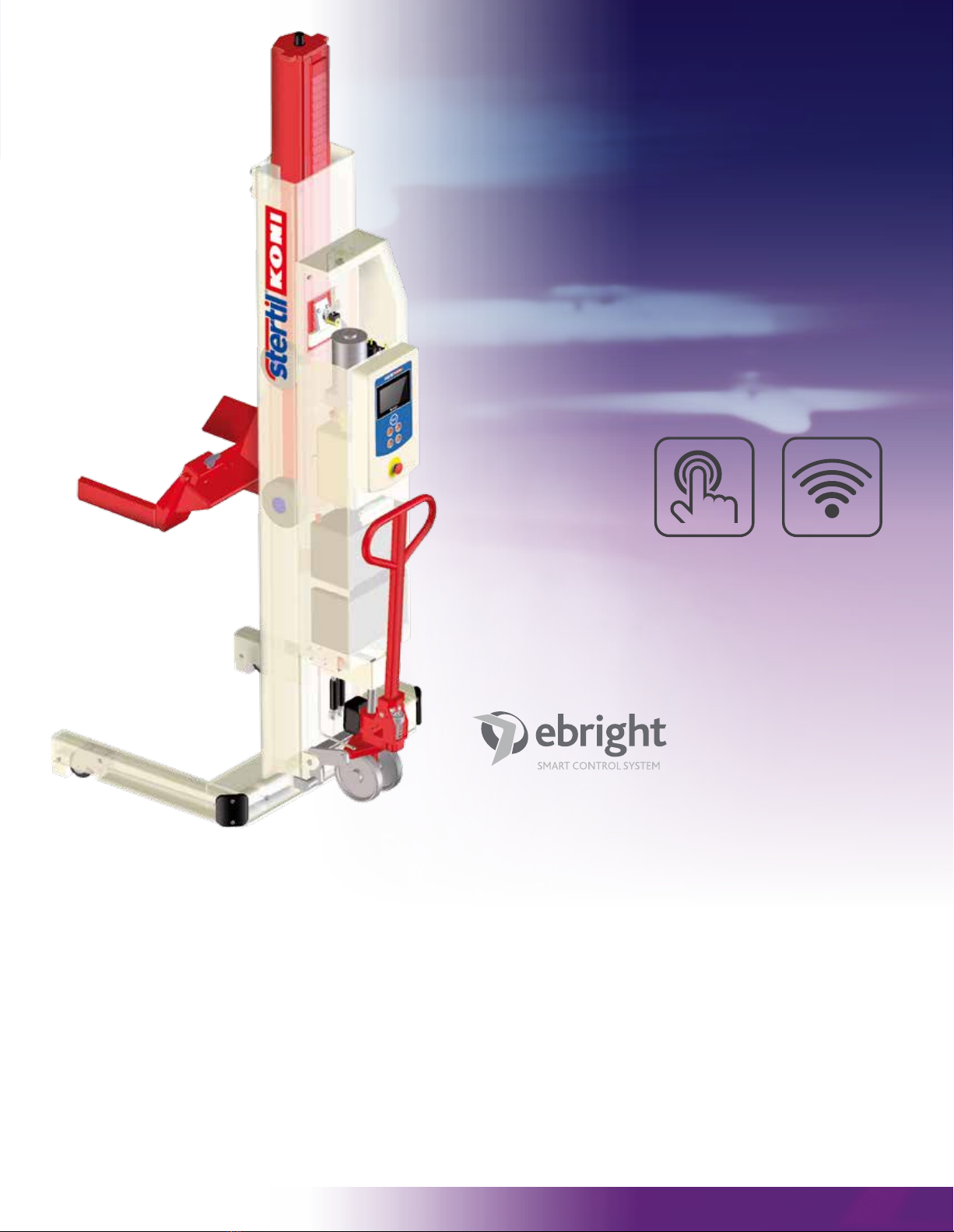
Full color touch screen control
The revolutionary ebright Smart Control System
combines intuitive ease of use with maximum visual
information about the lifting process. The main advantages:
•
7" full color touch screen, works even when wearing gloves
•User-configured options, such as choice of language,
safety warnings and scheduled maintenance notifications
•All relevant information available at a glance
•Customizable ID-Key to prevent unauthorized operation
•Wireless Mesh network for optimal connectivity
… or cabled, it’s up to you
If you predominantly work in a fixed location the cabled
mobile column lifts could be the best solution for you.
This setup offers the possibility to connect up to 32 columns
in a single lift set. All interconnection cables are equipped
with heavy-duty plugs at both ends.
Both the wireless and the cabled column lifts are equipped
with a control panel on each individual column. Columns
can be operated individually, in pairs or simultaneously as
a complete set with the touch of a button. Each column
can therefore be used at any given location.
Wireless mobile
column lifts
with ebright Smart
Control System
TOUCH SCREEN WIRELESS

Power supply
The Stertil-Koni wireless mobile column lifts operate on
24 VDC and are easily recharged by means of a 110 VAC
wall receptacle. The Stertil-Koni cabled mobile column lifts
operate on three phase at 208/230, 460/480 and
575 VAC, as well as single phase at 220 VAC.
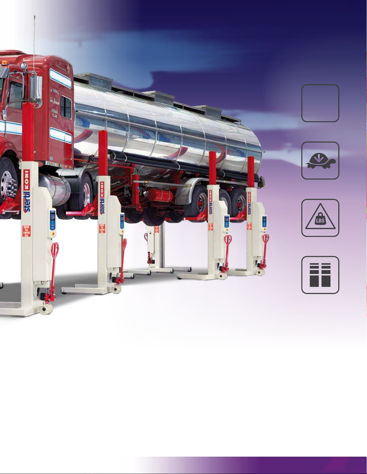
Fast lifting and lowering
The ST 1085 and ST 1100 only take 94 seconds to reach
its maximum lifting height of 73". This makes them one of
the fastest mobile column lifts in the world.
Reliable hydraulic technology
•Extended column life and minimal maintenance
thanks to low-friction design
•Stringent testing before leaving the factory
•Manual lowering in case of a power outage
•Maximum protection of the cylinder and
seal against damage
Adjustable pick-up forks
ST 1085 mobile column lifts have a fork length of 14",
ideal for picking up a variety of vehicles, including vehicles
with super single tires in a safe and secure manner.
The fork length for the ST 1100 mobile column lift is 12".
Both models can handle wheels with rim diameters from
R12 to R22.5 with an adjustable fork that is easy to
move manually and includes a mechanical lock.
Retractable wheels
Both the wireless and the cabled mobile column lifts are
available with retractable wheels. This unique Stertil-Koni
design is the best available on the market. This prevents
high point loading on the floor and reduces the floor
surface pressure by a factor of 10. The system is fast,
efficient, very stable and extremely reliable.
Adjustable lowering speed
If you need to lower the vehicle more slowly for precision
placement of under carriage components, this is easily
done with a single touch.
Unique synchronization
The synchronization system is activated at a height
difference of just 9/16". This ensures a safe and smooth
lifting and lowering cycle, even in cases where the
distribution of the vehicle weight is extremely uneven.
Lifetime guarantee
The innovative synthetic runner wheels within the column
come with a lifetime parts guarantee.
Easy to move
Stertil-Koni mobile column lifts are indeed mobile, thanks
to the synthetic roller wheels and hydraulic pallet jack
mechanism with patented overload protection.
Safe working space
As an extra safety feature, we have also designed ample
working space between the column and the vehicle.
This ensures that the vehicle will not come into contact with
the column in the event of sagging vehicle suspension.
MAX 32 LINKED
COLUMNS
UNIQUE
SYNCHRONIZATION
SYSTEM
MAX
32
OVERLOAD
PROTECTION
ADJUSTABLE
LOWERING SPEED
Well thought out
in all aspects

High resolution
7" touch screen
Intuitive controls
•Tracking of specific operations and
information codes
•Intuitive controls with actual data about the lift:
- Indication for Single, All or Pair operation mode
- Information about how many columns are
in the set (up to 32 columns)
- Actual lifting height displayed
- Lowering speed can be manually adjusted
on the touch screen
- Battery status information
- Customizable ID-Key to prevent unauthorized
operation
•Wireless Mesh network with continuous active
channel search offering optimal connectivity
•High resolution 7” touch screen
•Owner/User configurable system with user ID key
- Individual user settings for setting language
and units of measure
- Protection against unauthorized use, thanks to
personalized ID key
•Maintenance notifications
•Visual display of maximum programmable lifting
height
•Warning and failure information
•Operation manual available on-screen
Features

Overview of ST 1085 – ST 1100
models
ebright
wireless
ST 1085-FWA
ST 1100-F WA
ebright
wireless
ST 1085-RWA
ST 1100-RWA
ebright
cabled
ST 1085-FSA
ST 1100-FSA
ebright
cabled
ST 1085-RSA
ST 1100-RSA
ebright Smart Control System with a control box
on each individual mobile column
••••
Touch screen with important information about
the system e.g. lifting height, operation mode
••••
Wireless Mesh network with continuous active
channel search offering optimal connectivity
• •
These columns utilize a power outlet in the
workshop and communicate with each other via
interconnecting cables
• •
Adjustable lowering speed for slow or
normal lowering
••••
Hydraulic pallet truck mechanism with patented
overload protection
••••
14"-long adjustable fork, suitable for
super single tires ST 1085 ST 1085 ST 1085 ST 1085
12"-long adjustable fork S T 110 0 S T 110 0 S T 110 0 S T 110 0
Fixed synthetic wheels that reduce the floor
surface pressure
• •
Retractable synthetic wheels integrated into
the base frame, for 10x less floor pressure
• •
Everything
under
control

10”
33”
47 1/4”
14”*
44”
9 3/8”-22”
34 1/2”
49 1/4”
14”*
44”
9 3/8” - 22”
4”
143 1/2”
97”
73”
6”
10”
4”
143 1/2”
97”
73”
6”
a member of the Stertil Group
95003902 ST1085 - ST1100 USA 02-2017. Stertil is a registered trademark of Stertil B.V.. We reserve the right to make changes in specifications without notice and without making changes retroactive.
Technical specifications
Lifting capacity: 18,500 lbs. or 22,000 lbs.
Lift system: hydraulic lifting system with
microprocessor-controlled
synchronization
Lifting height: maximum 73", automatic stop at
the highest position
Lifting time: 94 seconds
Motor rating: 3 hp / 4 hp per column
(Cabled/Wireless)
Weight: 1,350 lbs per column (Wireless)
Column lift height: 97"
Highest safety requirements
• ANSI/ALI-ALCTV certified (USA), CSA certified
(Canada), CE certified (Europe)
• Independent mechanical locking system engages
at 5" above finished floor. Locking pawl engaged by
gravity. The locking system is always active, even
when the column is turned off
• Locking profile with locking increments of just 1 3/8"
• Synchronization between the mobile lifting columns
starts at a height difference of 9/16"
• Automatic overload protection
• Low voltage control panel with emergency stop
• Each column is equipped with hold-to-run
push buttons
• Each individual mobile lifting column is tested prior to
leaving the factory
• Splash-proof electrical system (IP 65).
Accessories & options
Stertil-Koni offers an extensive package of accessories
& options tailored to fit your specific needs. More information?
For more information about the ST 1085, ST 1100,
or any of Stertil-Koni's other top products, please
do not hesitate to contact us. We will be pleased
to assist you.
Fixed front wheels Adjustable forks
Adjustable forksRetractable front wheels
* For the ST 1100: 12"
Stertil-Koni U.S.A. Inc.
200 Log Canoe Circle
Stevensville, Maryland 21666
Tel. 410-643-9001
Toll free 800-336-6637
Fax 410-643-8901
www.stertil-koni.com
StertilKoniUSA @StertilKoniUSA

14 45 00-1
DIVISION 14 45 00
VEHICLE LIFTS(ST 1085 FWA ebright)
PART 1 GENERAL
1.1 SECTION INCLUDES
A. Mobile column lifts.
1.2 RELATED SECTIONS
A. Section 03 30 00 - Concrete: Footings and foundations.
B. Section 26 05 00 - Common Work Results for Electrical.
1.3 SUBMITTALS
A. Submit under provisions of Section 01 30 00 - Administrative Requirements.
B. Product Data: Manufacturer's data sheets on each product to be used, including:
1. Preparation instructions and recommendations.
2. Storage/handling requirements and recommendations.
3. Installation methods.
C. Shop Drawings: Submit drawings showing full layout of all lifts with dimensions
D. Operation and Maintenance Manual: Submit Operation and Maintenance manual to
include system operation, maintenance and troubleshooting, spare part numbers,
drawings and schematics.
1.4 QUALITY ASSURANCE
A. Manufacturer Qualifications: The lift company selling the product shall have
ISO-9001 certification and the proof of current certification shall accompany the bid.
B. Installer Qualifications: For warranty validation, installation shall be performed by
qualified factory authorized and trained personnel.
C. Product Requirements:
1. Design Standards and Certification: The lift shall be certified by ETL/Intertek
to the ANSI/ALI ALCTV-current edition Standard for Automotive Lifts: Safety
Requirements for Construction, Testing and Validation.
2. The drive system shall permit lifting without any pulsation, jerks, or unsteady
lifting. Lifting shall be smooth. System shall be comprised of an electrically
powered pump, flow control valves, and a fluid reservoir. An
electronic/hydraulic synchronization system shall ensure smooth alignment of
each lifting assembly based on variances in vehicle weight. A microprocessor
shall control all lift movement for ultimate operator safety and convenience.
Troubleshooting codes shall facilitate service and repair.

14 45 00-2
1.5 DELIVERY, STORAGE, AND HANDLING
A. Store products in manufacturer's unopened packaging until ready for installation.
B. Store and dispose of solvent-based materials, and materials used with
solvent-based materials, in accordance with requirements of local authorities having
jurisdiction.
1.6 PROJECT CONDITIONS
A. Maintain environmental conditions (temperature, humidity, and ventilation) within
limits recommended by manufacturer for optimum results. Do not install products
under environmental conditions outside manufacturer's absolute limits.
1.7 WARRANTY
A. Manufacturer's Warranty: Lift system shall be warranted for a minimum period of 2
years for parts and 1 year for labor. Hydraulic cylinder shall have a parts only
warranty of an additional four years. Guide rollers shall have a lifetime warranty; this
extended warranty covers parts only.
PART 2 PRODUCTS
2.1 MANUFACTURERS
A. Acceptable manufacturer: Stertil-Koni USA, Inc., which is located at: 200 Log Canoe
Circle; Stevensville, MD 21666; Toll Free Tel: 800-336-6637; Tel: 410-643-9001;
Email: request info (lifts@stertil-koni.com); Web: www.stertil-koni.com
B. Requests for substitutions will be considered in accordance with provisions of
Section 00 26 00.
1. Requests for changes by the contractor on products, materials, equipment
and methods of construction required by the contract documents, after the
award, shall be considered requests for "substitutions", and shall follow the
procedures outlined within the bid documents for substitutions.
2. Any substitution of the specified lift requiring modifications of foundation
system detailed will be the responsibility of the contractor.
3. The contractor shall provide for any and all engineering and redesign of
foundation system as a result of substitution.
4. Under no circumstances will extra payment be permitted as a result of
additional work to accommodate any equipment substitution.
2.2 MOBILE COLUMN LIFTS
A. Mobile Column Lifts Model ST-1085-FWA(ebright) as manufactured by Stertil-Koni
USA, Inc.
1. General Description:
a. A lifting system or set (consisting of up to 32 columns) for vehicles
shall be composed of interchangeable columns. The size of the set
shall be able to be configured by the operator at time of set up without
the need to modify the operating system. It shall be possible to operate
up to 480 columns within any facility. With a set of up to 32 columns, it
shall be possible to operate any single column, a pair of columns, or all
columns together, at the same time.
b. Each column shall contain its own power supply which consists of two
deep cycle (group 31) 12 VDC batteries combined to provide a stable
24 VDC power supply.

14 45 00-3
c. The main power shall be fused between the primary power switch and
the motor/control circuits to protect against overload.
d. When fully charged, the on board battery power system shall be
capable of 19 lifting/lowering cycles at 100% of lifting capacity and 28
lifting/lowering cycles at 50% of lfiting capacity .
e. The 24 VDC on board power supply shall incorporate a built in
recharging systems with a pictograph on the display so the operator
can visually verify charging status.
1) The recharging system shall be a built in 110 VAC battery
charger with indicator lamps. The battery charger shall be
enclosed within a steel cabinet for protection from damage. The
charger indicator lamp shall be easily visible through a sight glass
mounted externally in the control cabinet. The indicator lamp shall
be illuminated steady red when the system is recharging, green
when batteries are fully recharged, and flashing green when the
charger is providing a trickle charge. It shall be possible to
operate the lifting column while the battery charger is actively
charging the batteries.
f. The base frame of the lifting column shall be of a rectangular design.
The contact pattern to the foundation under the column shall be
triangular in design to ensure uniform contact with the lifting foundation.
2. Lifting Capacity:
a. Each individual column shall have a nominal rated capacity of 18,500
lbs. (8,500 kg).
3. Dimensions:
a. The achieved lifting height of the column shall be no less than 73
inches (1,854 mm) when measured from the foundation on which the
column rests to the top of the lifting fork.
b. Column height shall not be greater than 97 inches (2,464 mm) when
fully lowered and 143.5 inches (3,645 mm) when the carriage has
achieved maximum height.
c. Column lifting fork shall be 14 inches in length.
4. Tire Size:
a. Wheel contact forks shall be adjustable by hand and freely accept tires
with rim diameters between R10 and R22.5. The adjustable forks shall
incorporate a mechanical locking device to ensure the fork cannot
relocate/adjust during use.
5. Pallet Jack Mechanism:
a. The pallet jack mechanism shall have a gas shock incorporated into its
design which shall serve two purposes. The primary purpose of the
pallet jack gas shock shall be to serve as a safety mechanism to
ensure that the mobile column is not lifting, while the pallet jack is
extended. If the operator fails to lower the pallet jack after column
positioning, as soon as the column experiences load during a lifting
cycle, the gas shock will retract to lower the column to its foundation for
stable lifting. The second purpose of the pallet jack gas shock shall be
to dampen the impact of floor imperfections experienced while the
column is relocated.
6. Wheels:
a. The column shall be fitted with fixed front roller wheels fabricated from
oil impregnated nylon so as to be non-destructive to the foundation on
which the column rests.
b. Floor pressure at the front roller wheel location shall be no greater than
7,200 lbs.
7. Drive Mechanism:
a. The drive system shall be hydraulic and shall permit lifting without any

14 45 00-4
pulsation, jerks, or unsteady lifting. Lifting shall be smooth. The
hydraulic power unit shall be an electrically-powered pump, flow control
valves, and a fluid reservoir.
b. Lifting carriage shall ride on durable, oil filled nylon guide rollers. Guide
rollers shall require no lubrication and no maintenance.
c. Each hydraulic cylinder shall be equipped with a hose burst check
valve to prevent decent in the event of a major fluid leak.
8. Controls:
a. The various functions of the mobile lifting system shall be initiated from
the control panels on the columns.
b. Each control box shall include:
1) "UP" button.
2) "Down" button.
3) “Lock release” button.
4) “Confirm” button
5) Mushroom style emergency stop button
6) A high definition 7 inch LCD screen touch. The touch screen
shall be specifically designed for a harsh workshop environment.
The touch screen shall be capable of providing the following
functions:
i. Column selection indicator: This area of the touch
screen display shall inform the operator of which columns in the
set have been selected for operation.
ii. Battery charge indicator: This area of the touch
screen display shall inform the operator of the charge condition of
the battery power supply.
iii. Column height indicator: This area of the touch
screen display shall inform the operator of the height of the
individual column. The operator shall have the ability to easily
toggle between individual imperial or metric units of height
measurement (inches or mm.). The column height indicator shall
also provide on the touch screen a clear indicator if the column has
been set to stop at a restricted lifting height. This indicator shall
be displayed as a thick horizontal line in the height display region
of the touch screen. As the column rises, the screen will mimic
the column and display the lifting fork rising up towards the
horizontal restricted height indicator bar. Once the lifting fork
shown on the display arrives at the restricted height indicator bar,
the column shall stop rising.
iv. Column speed indicator: This area of the touch
screen shall inform the operator of the speed of the lifting system.
The speed indicator shall have the ability to adjust the lowering to
30% of full lowering speed.
v. Column fault code indicator: When a fault code has
been registered by the control system, the touch screen shall
inform the operator of any fault codes affecting the lifting set. The
control system shall have the ability to display 42 individual fault
codes.
vi. One-touch access to the Guide screen: This area
of the touch screen provides to the operator access to the Guide
screen. The Guide screen shall provide to all system users:
i. Calculator
vii. One-touch access to the Information screen: This
area of the touch screen provides to the operator access to:
i. Owner information
ii. Service provider information

14 45 00-5
iii. Manufacturer information
viii. One-touch access to the Settings screen which
displays 5 options which allows management of :
i. Settings screen option (1): On this screen,
operators shall have the ability to change the
language displayed on the screen as well as the
units of measure for height and weight (imperial
or metric units).
ii. Settings screen option (2): On this screen,
operators shall have the ability to retract the
mechanical locks during raising for reduced
noise, as well as to set a restricted maximum
lifting height.
iii. Area to allow for future expansion
iv. Portal to the Shop screen: access to this screen
requires a PIN with details of the Shop Screen
provide below.
v. Portal to Information screen option: access to this
screen requires a PIN with details of the
Information Screen provide below.
ix. One-touch access to the Shop screen options
(access to the Shop screen shall be generally provided to only
maintainers and system administrators). The shop configuration
screen shall allow manipulation of:
i. Edit of owner’s details: on this screen shall be
the ability to edit the information displayed on
the Owner’s field.
x. Access to the Information Screen,which displays 9
options (access to the Information screen shall be generally
provided to only maintainers and system administrators). The
maintenance configuration screen shall allow manipulation of:
Screen 1
i. Initiation of foot protection which guards
against a crushing hazard during lowering.
This safety system, when enabled, will stop
lowering as the column reaches 18 inches
above finished floor. At that time, the operator
is provided a chance to inspect and ensure that
there are no obstructions in the area of the
vehicle and lifts. After confirmation that the
vehicle and lift area is clear of obstructions, the
operator simply needs to retract the mechanical
safety locks again and compete the lowering
cycle to bring the lift completely to the floor.
ii. Ability to disable height difference monitoring to
aid in trouble shooting. Once initiated, this
control system option allows the maintainer to
operate the lifting system outside normal safety
limits. This system is only for use by the lift
system maintainer during repair procedures.
This system option will automatically be
disabled and the control system returned to
default operating parameters after 10 minutes.
iii. Ability to apply a set value to height monitoring
system to aid in troubleshooting. Once
initiated, this control system option substitutes

14 45 00-6
a fixed value for the height monitoring device in
a particular column. This system is only for
use by the lift system maintainer during repair
procedures. This system option will
automatically be disabled and the control
system returned to default operating
parameters after 2 minutes.
Screen 2
i. Ability to select wireless operating channel to
minimize interference
ii. Ability to view total lift system run time to
properly plan for lift system maintenance.
iii. Ability to view individual column motor run time
to properly plan for lift system maintenance.
Screen 3 Area to allow for future expansion
Screen 4 (Safety Messages)-area to allow for future
expansion
Screen 5 (Maintenance Messages)-area to allow for
future expansion
Screen 6 (Back up and Restore)
I. Ability to restore control system to default
settings
Screen 7 (Software Version)
I. Ability to review system operating information
Screen 8
I. Ability to establish column type
II. Ability to establish motor type, VDC or VAC
III. Ability to establish control system
communication protocol
IV. Ability to enable or disable weight measuring
Screen 9 (Battery Settings)
i. Ability to establish at what voltage the system
will display that the battery system is WEAK
ii. Ability to establish at what voltage the system
will display that the battery system is EMPTY
c. All control panels shall have automatic synchronization through the full
stoke of the hydraulic cylinder with a maximum tolerance of 2 inches
(50 mm). Control system will actively control hydraulic correction to
maintain level synchronization, unless a column deviates more than 2.4
inches (60 mm) inches from any other column, at which point all motion
halts.
d. Each column shall be fitted with an individual analog height measuring
device. This height measuring device shall ensure that the height of
each column in the set remains synchronized at the height initiated by
the operator. The height measuring device shall also allow, through
single operation, that the operator can raise or lower any column to
alternate heights within the tolerances set by the ALI (Automotive Lift
Institute) in its manual entitled “Lifting It Right”.
e. The wireless communication system shall utilize mesh-style wireless
technology and be properly shielded from external interference in the
workshop.
f. The mobile column lift battery charger shall operate at the following
voltages: 110VAC.
g. Control panel shall be rated IP 65.
9. Safety Devices:
a. An independent and fail-safe mechanical locking system shall be

14 45 00-7
present on each column. This safety device shall be totally independent
from the lifting drive system.
b. Increments on lifting carriage locking profile shall not be greater than
1.375 inches (35 mm) and the first locking position shall engage after
no more than 5.0 inches (120 mm) of lifting.
c. A locking “pawl and ratchet” system shall be used to ensure proper and
automatic locking at any height and at all times. The locking notches
shall be integrated into the lifting carriage. The locking pawl shall be
mounted to the inside of the column and function as a wedge between
the column and the lifting carriage. The locking pawl design shall utilize
gravity, with a spring assist, to ensure the locking pawl is always
engaged into the locking ladder. The mechanical safety lock shall be
automatically engaged at all times when the lift is not operating.
PART 3 EXECUTION
3.1 EXAMINATION
A. Do not begin installation until substrates have been properly prepared.
B. If substrate preparation is the responsibility of another installer, notify architect of
unsatisfactory preparation before proceeding.
3.2 PREPARATION
A. Clean surfaces thoroughly prior to installation.
B. Prepare surfaces using the methods recommended by the manufacturer for
achieving the best result for the substrate under the project conditions.
3.3 INSTALLATION
A. Install in accordance with manufacturer's instructions. Test for proper operation, and
re-test if necessary until satisfactory results are obtained.
3.4 PROTECTION
A. Protect installed products until completion of project.
B. Touch-up, repair or replace damaged products before substantial completion.
END OF SECTION
This manual suits for next models
7
Table of contents
Other stertil-KONI Lifting System manuals


Popular Lifting System manuals by other brands


GEDA
GEDA AB 450 Assembly and operating manual

R. Beck Maschinenbau
R. Beck Maschinenbau HS 1200 FH operating manual

John Bean
John Bean 40HP210ES instruction manual

Stenhoj
Stenhoj MASCOT 1.25 Operation and maintenance instructions

Tuxedo
Tuxedo TP9KACX Installation & operation manual

Oshkosh
Oshkosh JLG 1930ES Service maintenance manual

BLUM
BLUM SERVO-DRIVE Problem Resolution

Elebia
Elebia NEO50 user manual

Rotary
Rotary SM65-51 Operation and maintenance manual

EZTRUNK
EZTRUNK 1900 0072 Assembly manual

WOOD'S POWR-GRIP
WOOD'S POWR-GRIP LJ6VH Guide to maintenance, troubleshooting, and repair

STARKE ARVID
STARKE ARVID Inlift Instructions for use