Hinowa LightLift 17.75 3S User manual

1
TECHNICAL COURSE
BOOKLET
LightLift 17.75 3S
LightLift 20.10 3S
PERFORMANCE
TTPE1720021602

2
COURSE CONTENTS
1. INTRODUCTION ...................................................................... 4
2. PERFORMANCE DATAS ............................................................ 5
2.1 PERFORMANCE TECHINCAL SPECIFICATIONS: ........................ 5
2.2.1 LL17.75 3S DIMENSIONS ........................................................ 6
2.2.2 LL17.75 3S WORKING AREA - 230 KG CAPACITY .................... 7
2.3.1 LL20.10 3S DIMENSIONS ........................................................ 8
2.3.2 LL20.10 3S WORKING AREA - 230 KG CAPACITY .................... 9
2.4 SERIAL NUMBER LOCATION .................................................. 10
3. SUMMARY OF REMOTE CONTROL FUNCTIONS ....................... 11
4. MACHINE IGNITION.............................................................. 12
4.1 GASOLINE ENGINE PRE-HEATING ......................................... 13
5. OPERATION AND SAFETY FEATURES OF THE MACHINE ......... 14
5.1 FUNCTIONING OF THE GROUND PART................................... 15
5.1.1 TRACKS OPERATION……………………………………………………….15
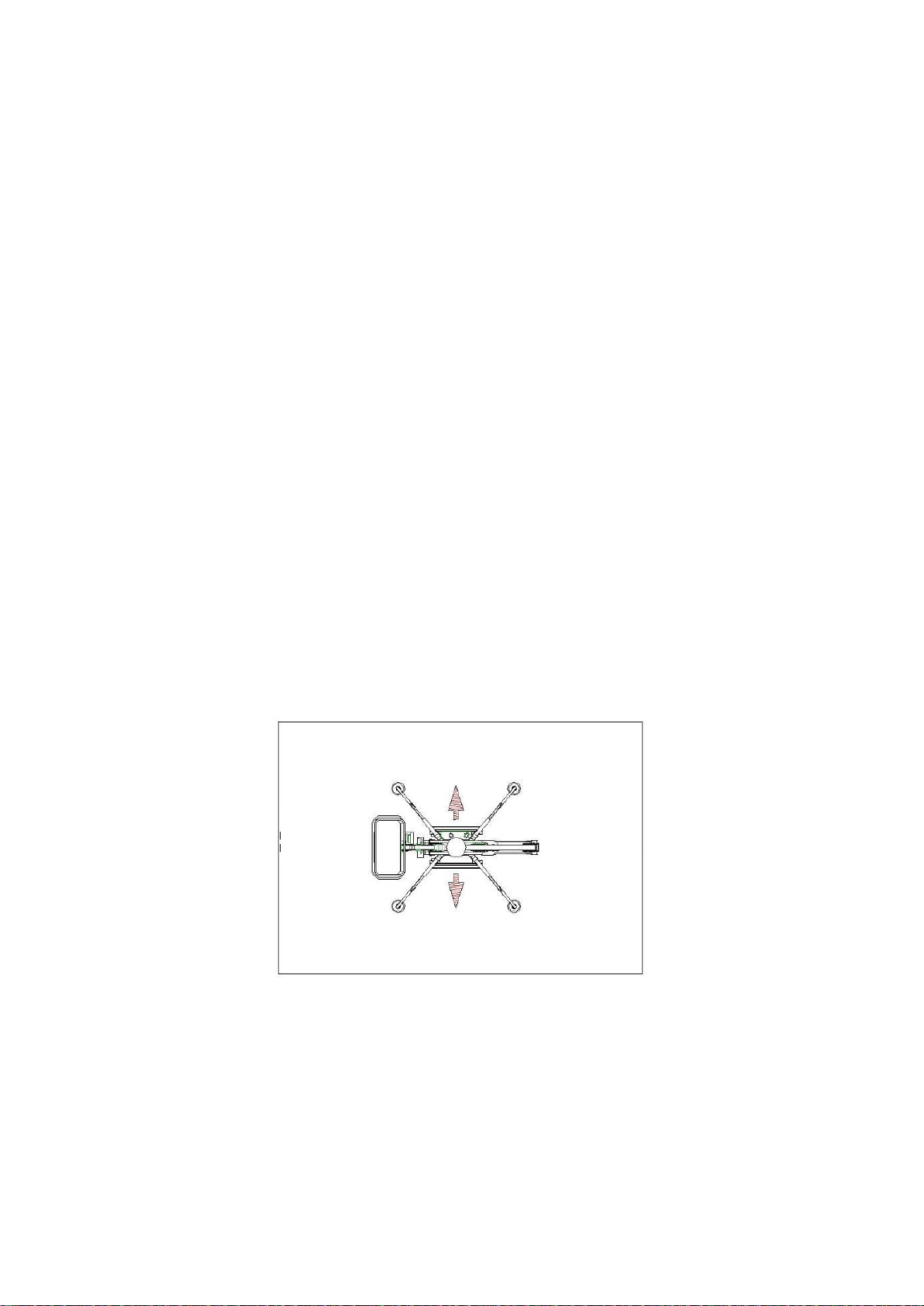
5.1.2 OUTRIGGER MOVEMENT………………………………………………….21
5.2 FUNCTIONING OF THE AERIAL PART..................................... 24
5.3 STOP BUTTONS ..................................................................... 26
5.4 PEDAL (OPTIONAL)............................................................... 27
6. EMERGENCY OPERATION ...................................................... 27
6.1 EMERGENCY OPERATIONS OF THE AERIAL PART .................. 29
6.1.1 GRAVITY EMERGENCY DESCENT............................................ 29
6.1.2 OPERATIONS FROM GROUND CONTROL POSITION............... 30
6.1.3 EMERGENCY DESCENT WITH SAFETIES BY-PASS .................. 31
6.1.4 EMERGENCY DESCENT WITH HAND PUMP............................. 32
6.2 EMERGENCY MOVEMENTS OF THE GROUND PART ................. 35
6.2.1 TRACK MOVEMENT WITH SAFETIES BY-PASS........................ 35
6.2.2 OUTRIGGERS MOVEMENT WITH THE MANUAL PUMP............. 36
6.3 ENGINES EMERGENCY START PROCEDURES .......................... 42
7. HYDRAULIC SYSTEM ............................................................. 45
7.1 COMPONENTS LOCATION ...................................................... 45
7.2 GROUND PART FUNCTIONING............................................... 48
7.3 AERIAL PART FUNCTIONING................................................. 51
8 ELECTRICAL SYSTEM............................................................. 55
8.1 CAN-BUS SYSTEM.................................................................. 55
8.2 CAN BUS DEVICES CONNECTION SCHEME ............................. 58
8.3 SAFETY DEVICES NOT IN CAN-BUS ....................................... 59
8.4 SAFETY DEVICES NOT IN CAN-BUS CONNECTION SCHEME.... 62

3
8.5 ELECTRONIC BOARDS LIGHT MEANINGS............................... 63
8.5.1 ECM1 (MASTER BOARD FRONT MODULE) LED CODE .............. 63
8.5.2 ECM2 (MASTER BOARD BACK MODULE) LED CODE ................ 64
8.5.3 ECM3 (LOAD CELL BOARD) LED CODE ................................... 64
8.5.4 110÷230V BOARD LED COD .................................................. 65
8.5.5 MODEM LED COD ................................................................... 65
9 ELECTRONIC BOARDS REPLACEMENT AND SETTING ............. 66
9.1 ELECTRONIC BOARDS SOFTWARE UPLOADER ....................... 66
9.2 ELECTRONIC BOARDS SOFTWARE INSTALLATION ................ 67
9.3 ELECTRONIC BOARDS SOFTWARE UPDATING ....................... 68
9.4 MASTER BOARD (ECM1-2) PARAMETERS SETTING ................ 69
9.5 LOAD CELL BOARD (ECM3) PARAMETERS SETTING ............... 69
10 POWER SUPPLY AND ELECTRIC MOTOR ................................ 69
10.1 ELECTRIC MOTOR.................................................................. 69
10.2 BATTERY CHARGE SYSTEM .................................................... 70
11 REMOTE CONTROL................................................................. 71
11.1 DISPLAY ICONS .................................................................... 71
11.2 ERROR MESSAGES –SELF DIAGNOSIS .................................. 72
11.3 DIAGNOSTICS ON THE DISPLAY ........................................... 73
11.4 FUNCTIONING OF THE REMOTE CONTROL ON THE GROUND . 81
11.5 LOAD CELL ............................................................................ 82
12. POWER SYSTEM .................................................................... 82
12.1 GASOLINE ENGINE HONDA IGX440....................................... 83
12.2 DIESEL ENGINE HATZ 1B40 (FOR 17.75 DIESEL) .................. 89
12.3 DIESEL ENGINE PERKINS 402.05 (FOR 20.10 DIESEL) ......... 92
12.4 LITHIUM VERSION (48V FOR 17.75, 72V FOR 20.10)............ 96
APPENDIX 1 - HYDRAULIC SYSTEM .................................................. 101
APPENDIX 2 - REMOTE CONTROL JOYSTICK REPLACEMENT ............. 104
APPENDIX 3 - CAN-BUS DIAGNOSTICS AND TROUBLESHOOTING .... 105
APPENDIX 4 - CURRENTS AND RAMPS SETTING............................... 112
APPENDIX 5 - LOAD CELL SYSTEM CALIBRATION PROCEDURE ........ 114
APPENDIX 6 - ACCELEROMETERS CALIBRATION PROCEDURE .......... 116
APPENDIX 7 - LIGHT INDICATION ON ELECTROVALVES………………..115
APPENDIX 8 - REMOTE CONTROL STOP BUTTON BY-PASS…… …..115
APPENDIX 9 - FREQUENTLY ISSUES SOLVING.................................. 118
APPENDIX 10 - MK2 PDATINGS…………………………….……………………121
4
THE PRESENT MANUAL HAS TO BE CONTEMPLATE SIMPLY WITH
INDICATIVE PURPOSE, IT DOESN'T REPLACE ANYHOW THE USE AND
MAINTENANCE MANUAL OF THE MACHINE.
THEREFORE ALWAYS REFER TO USE AND MAINTENANCE MANUAL FOR
ORDINARY AND EXTRAORDINARY USAGE, FOR MAINTENANCE, FOR
PROBLEM SOLVING AND GENERALLY FOR ANYTHING REGARDING THE
MACHINE.
1. INTRODUCTION
This booklet describes the technical and safety features, the electrical system
and the hydraulic system of the Hinowa LightLift 17.75 3S and 20.10 3S
Performance.
It does not include how to operate the machine, for this purpose see the
Operation and Maintenance Manual.
The first two digits of numerical part of the LightLift name identify the
maximum working height of the machine in meters, while the last two digits
indicate the maximum outreach in decimeters.
The aerial platform is equipped with an hydraulic system and an electrical
system that interact to ensure safe operating in any situation. The two systems
are described below, the present manual describes also how they interact.
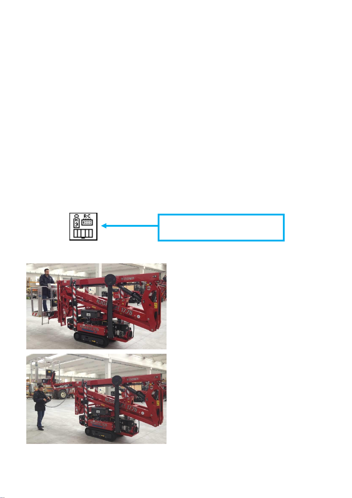
Remember that the operating position of the machine is established from
inside the basket, which is positioned in the rear. See the diagram below.
All the machine movements are controlled by the machine remote control
supplied with the machine. Usually, the remote control is positioned in the
specific seat in the basket, anyway there are others options illustrated and
described later.
Left Side
Right Side
Front
Side
Rear
Side

5
2. LL17.75 3S AND 20.10 3S PERFORMANCE DATAS
2.1 LL17.75 3S AND 20.10 3S PERFORMANCE TECHINCAL
SPECIFICATIONS:
LL1775
LL2010
Platform capacity
230 Kg
230 Kg
Max height (basket floor level)
14,96m
18.05m
Max working height
17,06m
20.15m
Basket dimensions (standard 2 persons
basket)
1335x690mm
134x69
Max working horizontal extension
7,00m
9,20m
Undercarriage width (Retracted/Extended)
798 / 1086mm
795 / 1095mm
Rotation (non-continuous)
360°
360°
Basket rotation
124° (+/- 62°)
124° (+/- 62°)
Max pressure on the ground for tracks
0,64 daN/cm²
0,67 daN/cm²
Max pressure on the ground for outrigger
2,45 daN/cm²
3,04 daN/cm2
N° of operators
2
2
N° operators for optional 1 person basket
1
1
Jib function
89° (+0° / -89°)
89° (+0° / -89°)
Max aerial part working inclination
1°/ 1,75%
1°/ 1,75%
Max slope tolerance
12°
15°
Petrol version dry weight (indicate in CE plate)
2190 Kg
2840 Kg
Petrol machine operating weight (without
operator)
2230 Kg
2880 Kg
Lithium machine operating weight (without
operator)
2300 Kg
2980 Kg
Max drive speed with thermic engine (with
double speed)
0,7 / 1,8 / (optional
3,6) Km/h (*)
0,5 / 1,3 / (standard
2,5) Km/h
Angle of attack
20° / 36,4%
20° / 36,4%
Max admitted translation inclination
16° / 28,7%
16° / 28,7%
Max wind speed
12,5 m/s
12,5 m/s
Max manual force allowed
400N
400N
Hydraulic pressure of ground part (tracks-
outriggers)
165bar
165bar
Hydraulic pressure aerial part
185bar
185bar
Hydraulic oil tank capacity
40 liters
40 liters
Electric system tension
12V
12V
Battery
12V 55Ah (*)
12V 55Ah (*)
AC electric motor
110V or 220V
50 Hz, 2.2KW
110V or 220V
50 Hz, 2.2KW
(*) (FROM LL17.75/4 and LL20.10/3 read APPENDIX 9)

6
2.2.1 LL17.75 3S PERFORMANCE DIMENSIONS
NOTE : standard version
with 2 persons basket

7
2.2.2 LL17.75 3S PERFORMANCE WORKING AREA - 230 KG CAPACITY

8
2.3.1 LL20.10 3S PERFORMANCE DIMENSIONS
NOTE : standard version
with 2 persons basket
9
2.3.2 LL20.10 3S PERFORMANCE WORKING AREA - 230 KG CAPACITY

10
2.4 SERIAL NUMBER LOCATION
A serial number plate is affixed on to the frame of the machine. The
following illustrations showing its location.
SERIAL NUMBER
PLATE LOCATION
11
3. SUMMARY OF REMOTE CONTROL FUNCTIONS
The remote control functions (commands and signals) of the LightLift 17.75 3S
and 20.10 3S Performance are briefly summarized below.
Engine
preheat
STOP
button
Gravity
emergency
descent
Automatic
destabilization
selector
Left track
1-2 arms
Jib
Turret
rotation
Right track
Main boom
Basket
rotation
Extension
Basket
leveling
key
Electric
motor
(start-stop)
Thermic
engine
(start-stop)
Undercarriage
closing
Automatic
stabilization selector
Undercarriage
widening
Engine speed
selector
Stabilizers manual
operating
Service
menu
selector
Display
Permission of aerial
part operation from
ground

12
The remote control is critical for the machine: it displays all the information on
the platform status and any error message in case of incorrect use of the
controls. It is also possible to access the SERVICE menu, which indicates any
anomalies or malfunctioning of machine components.
The icons on the display appear in 8 different positions, as illustrated above.
4. MACHINE IGNITION
(FOR LL17.75/4 and LL20.10/3 read APPENDIX 9)
To start up the machine, the battery cutter switch must be active, both the
stop buttons (the first on the remote control and the second on the ground
control box) must be released and ignition switch on the engine has to be
turned ON without start the engine.
To start the engine press remote control “thermic engine” button, to start the
electric motor press “electric motor“ button. With cold temperatures with petrol
engine it is recommended to press the preheat button after engine start and
wait 20 seconds before to start any movement. To stop the engine it is
possible to press a stop button or to press once again the button of engine
BATTERY
CUTTER
STOP
BUTTONS
IGNITION
SWITCH
TURNED “ON”

13
start. The display shows always in position 3 the motor selected, in case this
motor has been stopped the icon will be marked with an “X”.
If the operator tries to start up the machine with a
stop button pressed, the "ERROR STOP" message will
appear as illustrated here on side.
4.1 GASOLINE ENGINE PRE-HEATING
In case platform is equipped with gasoline engine, it is possible to pre-heat the
engine, increasing the rpm.
Pushing the “PREHEAT”button on the remote control engine runs for 20
seconds at 2200 rpm and the display visualizes the icon “PREHEAT
PROCEDURE IN PROGRESS”.
While preheating is in progress, any movement normally working at 2200 rpm
would work at 2200 rpm.
In case an aerial part movement working at 1500 or 3600 rpm is selected,
engine changes rpm to 1500 or 3600 and the heating procedure ends.
In case a track movement working at 1500 or 3600 rpm is selected, engine
changes rpm to 1500 or 3600 rpm, then it returns to 2200 rpm when
movement is released.
In case the power system is Lithium the rpm are different but the behavior will
be the same.
While preheating is in progress it’s not possible to move outriggers or to widen
the undercarriage.
ERROR
PREHEAT BUTTON
PREHEAT
PROCEDURE IN
PROGRESS
14
5. OPERATION AND SAFETY FEATURES OF THE MACHINE
The LL 17.75 3S and 20.10 3S Performance aerial platform are divided into two
main parts:
1. Ground part or undercarriage part
2. Aerial part
Operating in travel or stabilization mode, we are controlling the ground part;
on the other hand, moving the booms or the turret rotation we are controlling
the aerial part.
The ground or aerial part movements are managed by a control module
composed by different boards (indicated in the picture below) that interact
each other and with sensors or actuators installed in the machine. The load cell
board (ECM3) on the jib arm controls the weight in the basket and
communicates by CAN BUS with the master board (ECM1-2) located in the
electric component compartment on the ground part.
Another board (110÷230V BOARD) manages the functioning of the electric
motor and the charging of the battery when the machine is connected to the
110÷230V network.
This board communicates directly with the master board (ECM1-2).
A small board is located into the remote control (REMOTE CONTROL BOARD).
LOAD CELL BOARD
(ECM3)
MASTER BOARD (ECM1-2)
110÷230V BOARD
REMOTE CONTROL
BOARD
LOAD CELL BOARD
(ECM3)
MASTER BOARD (ECM1-2)
110÷230V BOARD
REMOTE CONTROL
BOARD
ON 20.10
ON 17.75
15
5.1 FUNCTIONING OF THE GROUND PART
5.1.1 TRACKS OPERATION
To allow tracks movement all the outriggers must be lifted from the ground.
When the operator is at the ground it is enough to act on the 2 outer red
joysticks to move the tracks. If the remote control is on the basket, it is
necessary to press the pedal (if pedal option is active) and act on the joystick
at the same time.
It’s possible to drive the tracks with the jib either closed or open in order to
move the machine on inclined slopes as well. To open the jib with machine not
stabilized, none of the outriggers can touch the ground and the operator must
control the machine from ground with remote control in hand (the remote
control cannot be in the support). It is enough to act on the joystick to move
the jib. If a joystick of another aerial part movement is operated an error
message appears on the display (“JIB ONLY”).
If there are more than 40 Kg weight in the basket or the remote control is in
its support in the basket, it is not possible to move the jib and on the display
appears an error message icon “REMOTE CONTROL OR LOAD ON BASKET”.
THE TRANSLATION WITH JIB
CLOSED IS POSSIBLE FROM
GROUND OR BASKET.
THE TRANSLATION WITH
OPENED JIB IS POSSIBLE
ONLY WITH OPERATOR AT THE
GROUND.
“REMOTE CONTROL OR LOAD
ON THE BASKET” ICON

16
MOVEMENT SPEED SELECTION FOR THE GROUND PART
Button 5 on remote control allows the operator to select the speed of the
ground part movement. To modify the movement speed, the machine changes
the rpm of the engine (electronically controlled). On the machine equipped
with the double speed drive gear motors, it is available one speed more
(HARE) acting on the chamber of the drive gear motors (slow gear- fast gear).
Pushing button 5 to select the speed, the speed icon will appear in position 4 of
the display. If no movement is made the engine keeps the minimum speed
(1500 rpm for gasoline engine).
THERMIC ENGINE (GASOLINE –DIESEL)
a) TURTLE:
b) NORMAL:
c) HARE:
NOTE: Auxiliary electric motor works always at minimum speed (1500 rpm).
LITHIUM SYSTEM
a) TURTLE:
b) NORMAL:
c) HARE:
AUTOMATIC SPEED CONTROL FOR STABILITY REASON
LL17.75 and LL20.10 are provided with a special system that automatically
reduces tracks speed or stops the movement in case of stability risks.
This control depends automatically on different factors:
-Weight in the basket
-Jib opened or closed
-Tracks widened or not
-Slope inclination gradient in axles X and Y
OPTIONAL: If equipped with double speed drive
gear motors the engine runs always at 3600
rpm for the undercarriage part and the drive
gear motors switch to high speed (max 3,6
Km/h).
The engine runs always at 3600 rpm for the
undercarriage part but the drive gear motors
keep the slow speed (max 1,8 km/h).
The engine runs at 1500 rpm (1850 on diesel).
OPTIONAL: If equipped with double speed drive
gear motors the engine runs always at 2550
rpm for the undercarriage part and the drive
gear motors switch to high speed.
The engine runs always at 2550 rpm for the
undercarriage part but the drive gear motors
keep the slow speed.
The engine runs at 1050 rpm.

17
The consequence of a stability emergency is, with increasing severity:
a) Tracks speed reduction
b) Tracks movement stopped, display icon
Moreover the buzzer on the remote control could be activated.
WARNING: To move the tracks when the machine is stopped by those
conditions it’s necessary to press button 8 on remote control, a counter-down
of 10 seconds will be activate on the display and in the meantime tracks
movement is allowed in turtle speed with beeper ON. During that by-pass the
operator can bring machine back to stability condition.
SPEED CONTROL POSSIBLE CONDITIONS ON THE LL17.75
JIB
OPEN
Not possible
to select
HARE
X or Y >5°
TURTLE
Y>7°
TURTLE +
BUZZER
Y>13°
BUZZER +
MOVEMENT
STOPPED+
ALARM
ICON
UNDERCARRIAGE
CLOSED
X>6°
TURTLE +
BUZZER
X>10°
BUZZER +
MOVEMENT
STOPPED+
ALARM
ICON
UNDERCARRIGE
WIDENED
X>10°
TURTLE +
BUZZER
X>15°
BUZZER +
MOVEMENT
STOPPED+
ALARM
ICON
AXLE X
AXLE Y
18
JIB
CLOSED
Weight inside
basket
<=120Kg
Possible to
select HARE
X or Y >8°
TURTLE
Y>10°
TURTLE +
BUZZER
Weight inside
basket <=40kg
Y>16°
BUZZER +
MOVEMENT
STOPPED +
ALARM
ICON
Weight inside
basket
>40kg<=120Kg
Y>13°
BUZZER +
MOVEMENT
STOPPED +
ALARM
ICON
UNDERCARRIAGE
CLOSED
X>6°
TURTLE +
BUZZER
X>10°
BUZZER +
MOVEMENT
STOPPED +
ALARM
ICON
UNDERCARRIAGE
OPEN
X>10°
TURTLE +
BUZZER
X>15°
BUZZER +
MOVEMENT
STOPPED +
ALARM
ICON
Weight inside
basket
>120<=230Kg
Not possible
to select
HARE
X or Y >5°
TURTLE
Y>7°
TURTLE +
BUZZER
Y>13°
BUZZER +
MOVEMENT
STOPPED +
ALARM
ICON
UNDERCARRIAGE
CLOSED
X>6°
TURTLE +
BUZZER
X>10°
BUZZER +
MOVEMENT
STOPPED +
ALARM
ICON
UNDERCARRIAGE
OPEN
X>10°
TURTLE +
BUZZER
X>15°
BUZZER +
MOVEMENT
STOPPED +
ALARM
ICON
Weight inside
basket
>230Kg
MAX
WEIGHT
ALARM +
MOVEMENT
STOPPED

19
SPEED CONTROL POSSIBLE CONDITIONS ON THE LL20.10
JIB
OPEN
Not possible
to select
HARE
X or Y >6°
TURTLE
Y>13°
TURTLE +
BEEPER
Y>20° BASKET DOWNSTREAM
OR
Y>16° BASKET UPSTREAM
BEEPER +
MOVEMENT
STOPPED+
ALARM
ICON
UNDERCARRIAGE
CLOSED
X>8°
TURTLE +
BEEPER
X>10°
BEEPER +
MOVEMENT
STOPPED+
ALARM
ICON
UNDERCARRIGE
WIDENED
X>10°
TURTLE +
BEEPER
X>15°
BEEPER +
MOVEMENT
STOPPED+
ALARM
ICON
20
JIB
CLOSED
Weight inside
basket
<=120Kg
Possible to
select HARE
X or Y >6°
TURTLE
Y>13°
TURTLE
+BEEPER
Y>20° BASKET DOWNSTREAM
OR
Y>16° BASKET UPSTREAM
BEEPER +
MOVEMENT
STOPPED +
ALARM
ICON
UNDERCARRIAGE
CLOSED
X>8°
TURTLE +
BEEPER
X>10°
BEEPER +
MOVEMENT
STOPPED +
ALARM
ICON
UNDERCARRIAGE
OPEN
X>10°
TURTLE +
BEEPER
X>15°
BEEPER +
MOVEMENT
STOPPED +
ALARM
ICON
Weight inside
basket
>120<=230Kg
Not possible
to select
HARE
X or Y >6°
TURTLE
Y>10°
TURTLE +
BEEPER
Y>15°
BEEPER +
MOVEMENT
STOPPED +
ALARM
ICON
UNDERCARRIAGE
CLOSED
X>8°
TURTLE +
BEEPER
X>10°
BEEPER +
MOVEMENT
STOPPED +
ALARM
ICON
UNDERCARRIAGE
OPEN
X>10°
TURTLE +
BEEPER
X>15°
BEEPER +
MOVEMENT
STOPPED +
ALARM
ICON
Weight inside
basket
>230Kg
MAX
WEIGHT
ALARM +
MOVEMENT
STOPPED
This manual suits for next models
3
Table of contents
Other Hinowa Boom Lift manuals

Popular Boom Lift manuals by other brands

Genie
Genie Z-45/25 Operator's manual

Terex
Terex Z4525XCF-101 Operator's manual

Genie
Genie ZX-135/70 with Jib-Extend Service and repair manual

Oshkosh Corporation
Oshkosh Corporation JLG E600 Operation and safety manual

Mec
Mec TITAN Boom 40-S Operator's manual

Genie
Genie Z-45/25 operators manual with maintenance information


