Hioki 3269 User manual

3269
POWER SUPPLY
Instruction Manual
December 2014 Revised edition 6 3269A981-06 14-12H


i
Contents
Contents
Introduction ...............................................................1
Inspection..................................................................1
Safety Notes .............................................................2
Operating Precautions ..............................................5
Chapter 1 Overview 9
1.1 Product Overview........................................9
1.2 Names of Parts............................................9
Chapter 2 Measurement Procedure 11
2.1 Preparations............................................. 11
2.2 Measurement Procedure...........................12
Chapter 3 Specifications 13
Chapter 4 Maintenance and Service 15
4.1 Cleaning and Service ................................15
3269A981-06

Contents
ii

1
Introduction
Thank you for purchasing the HIOKI Model 3269
Power Supply. To obtain maximum performance
from the device, please read this manual first, and
keep it handy for future reference.
When you receive the device, inspect it carefully to
ensure that no damage occurred during shipping.
If damage is evident, or if it fails to operate accord-
ing to the specifications, contact your dealer or
Hioki representative.
Supplied accessories
• Power cord.....................................................1
• Instruction Manual..........................................1
Introduction
Inspection

Safety Notes
2
This manual contains information and warnings
essential for safe operation of the device and for
maintaining it in safe operating condition. Before
using it, be sure to carefully read the following
safety precautions.
Safety Notes
This device is designed to comply with IEC
61010 Safety Standards, and has been thor-
oughly tested for safety prior to shipment.
However, mishandling during use could
result in injury or death, as well as damage to
the device. Using the device in a way not
described in this manual may negate the pro-
vided safety features.
Be certain that you understand the instruc-
tions and precautions in the manual before
use. We disclaim any responsibility for acci-
dents or injuries not resulting directly from
device defects.

3
Safety Notes
Safety Symbols
The following symbols in this manual indicate the
relative importance of cautions and warnings.
In the manual, the symbol indicates particu-
larly important information that the user should
read before using the device.
The symbol printed on the device indicates
that the user should refer to a corresponding topic
in the manual (marked with the symbol) be-
fore using the relevant function.
indicates a grounding terminal.
Indicates AC (Alternating Current).
Indicates the ON side of the power switch.
Indicates the OFF side of the power switch.
Indicates that incorrect operation presents an ex-
treme hazard that could result in serious injury or
death to the user.
Indicates that incorrect operation presents a sig-
nificanthazardthatcould result in serious injury or
death to the user.
Indicates that incorrect operation presents a pos-
sibility of injury to the useror damage to the device

Safety Notes
4
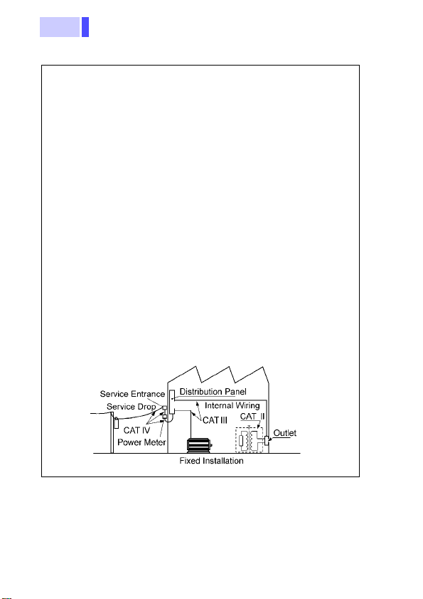
Toensuresafe operation ofmeasurementdevices,IEC 61010
establishes safety standards for various electrical environ-
ments, categorized as CAT II to CAT IV, and called measure-
ment categories.
CAT II: Primary electrical circuits in equipment connected to
anACelectricaloutlet by a power cord (portabletools,
household appliances, etc.)
CAT II covers directly measuring electrical outlet re-
ceptacles.
CAT III:Primary electrical circuits of heavy equipment (fixed
installations) connected directly to the distribution
panel, and feeders from the distribution panel to out-
lets.
CAT IV:The circuit from the service drop to the service en-
trance, and to the power meter and primary overcur-
rent protection device (distribution panel).
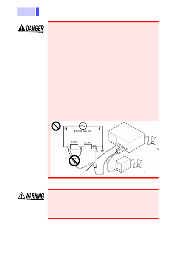
Using a measurement device in an environment designated
with a higher-numbered category than that for which the de-
vice is rated could result in a severe accident, and must be
carefully avoided.
Use of a measurement instrument that is not CAT-rated in
CAT II to CAT IV measurement applications could result in a
severe accident, and must be carefully avoided.
Measurement categories

5
Operating Precautions
Follow these precautions to ensure safe operation
and to obtain the full benefits of the various func-
tions.
Before using the device for the first time, verify that
it operates normally to ensure that no damage
occurred during storage or shipping. If you find any
damage, contact your dealer or Hioki representa-
tive.
Operating Precautions
Before Use

Operating Precautions
6
• To avoid accidents, when using other mea-
surement devices with this one, observe
the usage precautions described for each
device.
• When using a measurement instrument
that does not provide isolation between its
input terminals and chassis or other input
terminals, please pay attention to the fol-
lowing points.
If a signal is applied to an input terminal
other than that to which the current probe
is connected, do not connect the ground-
side terminal to any non-ground potential.
Otherwise, short-circuit current will flow
through the current probe or this device
from the ground terminal, which could
cause an electrical accident or damage.
Current Probe
To avoid electrical accidents and to maintain
the safety specifications of this device, con-
nect the power cord only to a 3-contact (two-
conductor + ground) outlet.

7
Operating Precautions
Observe the following to avoid damage to the
device.
• Installation and Operating Environment
Between 0 and 40°C (32 and 104°F); 80%RH or
less; indoors only.
• Do not store or use the device where it could be
exposed to direct sunlight, high temperature or
humidity, or condensation. Under such condi-
tions, the device may be damaged and insula-
tion may deteriorate so that it no longer meets
specifications.
• This device is not designed to be entirely water-
or dust-proof. To avoid damage, do not use it in
a wet or dusty environment.
• To avoid damage to the device, protect it from
physical shock when transporting and handling.
Be especially careful to avoid physical shock
from dropping.
• To avoid damaging the power cord, grasp the
plug, not the cord, when unplugging it from the
power outlet.

Operating Precautions
8

9
Chapter 1 Overview
This unit is the power supply dedicated to Models
3273-50, 3273, 3274, 3275, and 3276 Clamp on
Probe (hereafter referred to as the "current
probe"), as well as Models CT6700 and CT6701
Current Probe. The unit can supply power to up to
four current probes.
Overview Chapter 1
1.1 Product Overview
1.2 Names of Parts
Front view
Power supply receptacles
Power indicator
2
3
4
The pin assignment of the receptacles
1 Not used
2 Ground
3 -12V
4 +12V 1

Chapter 1 Overview
10
Rear view
ON
OFF
Power switch
Grounding
terminal
Power supply
connector

11
Chapter 2 Measurement Procedure
Measurement
Procedure Chapter 2
2.1 Preparations
• To avoid accidents, when using other mea-
surement devices with this one, observe
the usage precautions described for each
device.
• When using a measurement instrument
that does not provide isolation between its
input terminals and chassis or other input
terminals, please pay attention to the fol-
lowing points.
If a signal is applied to an input terminal
other than that to which the current probe
is connected, do not connect the ground-
side terminal to any non-ground potential.
Otherwise, short-circuit current will flow
through the current probe or this device
from the ground terminal, which could
cause an electrical accident or damage.
Current Probe

Chapter 2 Measurement Procedure
12
1. Turn the power switch off and connect the power
cord.
To avoid electrical accidents and to maintain the
safety specifications of this device, connect the
power cord only to a 3-contact (two-conductor +
ground) outlet.
2. Connect the power plug of the sensor to be used
to the power receptacle of the 3269.
3. Turn the 3269 power switch on, and check that the
front panel power indicator lights.
See the 3273-50, 3273, 3274, 3275, 3276,
CT6700, or CT6701 instruction manual.
Before turning the device on, make sure the
supply voltage matches that indicated on its
power connector. Connection to an improper
supply voltage may damage the device and
present an electrical hazard.
2.2 Measurement Procedure

13
Chapter 3 Specifications
Product Specifications
Specifications Chapter 3
Compatible sensors 3273-50, 3273, 3274, 3275, 3276,
CT6700, CT6701
Number of power
supply connectors 4
Output voltage ±12 V±0.5 V
Rated output current ±2.5 A (sum total of all channels)
Ripple voltage 50 mVp-p or less
Load influence Within output voltage limits indicated above
for current output in the range 0 to ±2.5 A
Temperature influ-
ence Within output voltage limits indicated
above for ambient temperature in the
range 0 to 40°C (32 to 104°F)
Rated supply volt-
age 100 to 240V AC (50/60Hz)
(Voltagefluctuationsof±10%fromtherated
supply voltage are taken into account.)
Maximum rated
power 170 VA
Operating tempera-
ture and humidity
range 0 to 40°C(32 to 104°F),80%RH or less
(no condensation)
Storage temperature
and humidity range -10 to 50°C(14 to 122°F), 80%RH or less
(no condensation)
Location for use Indoor, altitude up to 2000 m (6562 feet)
Dimensions, Mass Approx.80W × 119H × 200D mm
(3.15"W × 4.69"H × 7.87"D)
Approx.1.2 kg (42.3 oz.)
Accessories Instruction Manual
Power cord
Standards applying Safety EN61010, Pollution Degree 2
EMC EN61326,EN61000-3-2,
EN61000-3-3

Chapter 3 Specifications
14
Memo

15
Chapter 4 Maintenance and Service
• To clean the device, wipe it gently with a soft
cloth moistened with water or mild detergent.
Never use solvents such as benzene, alcohol,
acetone, ether, ketones, thinners or gasoline, as
they can deform and discolor the case.
• If damage is suspected, contacting your dealer
or Hioki representative.
• When sending the device for repair, pack care-
fully to prevent damage in transit. Include cush-
ioning material so the device cannot move within
the package. Be sure to include details of the
problem. Hioki cannot be responsible for damage
that occurs during shipment.
Maintenance and
Service Chapter 4
4.1 Cleaning and Service

Chapter 4 Maintenance and Service
16
Memo
Other manuals for 3269
1
Table of contents
Other Hioki Power Supply manuals