HIOS VZ-1510 User manual

Transformerless Screwdriver
100V
VZ-1510/VZ-1510PS
VZ-1812/VZ-1812PS
VZ-1820/VZ-1820PS/VZ-3012/VZ-3012PS/
VZ-3007/VZ-3007PS
VZ-4506/VZ-4506PS with Shockless Stand
120V
VZ-1820/VZ-1820PS/VZ-3012/VZ-3012PS/
VZ-4506/VZ-4506PS
220-240V
VZ-1812/VZ-1812PS/VZ-3007/VZ-3007PS/
VZ-4504/VZ-4504PS
ET-A003 20A
Electric Screwdriver
VZ Series
Operation Manual
(September 2020)

- 2 -
SAVE THESE INSTRUCTIONS
We thank you for your purchase of Hios Electric Screw Driver.
WARNING
When using electric tools, basic safety precautions should
always be followed to reduce the risk of re, electric shock and
personal injury, including the following:
READ ALL INSTRUCTIONS
1. Keep Work Area Clean.
Cluttered areas and benches invite injuries.
2. Consider Work Area Environment.
Don't expose tool to rain. Don't use tool in damp or wet
locations.
Keep work area well lit.
Never use the tool at an area with dangerous object. (gasoline,
benzene, thinner, gas glue, etc.)
3. Secure Work.
Use clamps or vise to hold work. It's safer than using your hand
and it free both hands to operate tool.
4. Guard Against Electric Shock.
Prevent body contact with grounded surfaces, for example:
pipes, radiators, ranges, refrigerator enclosures.
5. Keep Children Away.
Do not let visitors contact tool. All visitors should be kept away
from work area.
6. Store Idle Tools.
When not in use, tools should be stored in dry, and high or
locked-up place out of reach of children.
7. Don't Force Tool.
It will do the job better and safer at the rate for which it was
intended.
8. Remove Adjusting Keys And Wrenches.
From habit of checking to see that keys and adjusting
wrenches are removed from tool before turning it on.
9. Use Right Tool.
Use the tool for the proper work against its power and
intended purpose.

- 3 -
10. Dress Properly.
Do not wear loose clothing or jewelry. They can be caught
moving parts.
Wear protective hair covering to contain long hair.
11. Use Safety Glasses.
Also use face or dust mask if operation is dusty.
12. Don't Abuse Cord.
Never carry tool by cord or yank it to disconnect from
receptacle.
Keep cord from heat, oil and sharp edges.
13. Don't Overreach.
Keep proper footing and balance at all times.
14. Maintain Tools With Care.
Keep tools sharp and clean for better and safer performance.
Follow instructions for lubricating and changing accessories.
To use the tool for long time safely, perform the periodical
inspection for the tool and if damaged, it must be repaired by
authorized service facility.
Keep hand dry, clean and free from oil and grease.
Inspect extension cords periodically and replace if damaged.
15. Disconnect Tools.
When not in use such as attaching and detaching the bit,
changing the Carbon Brush, inspection or cleaning, etc.,
disconnect tool.
16. Avoid Unintentional Starting.
Be sure switch is o when plugging in.
Don't carry tool with nger on switch.
16A.
Extension Cords.
Make sure your extension cords is in good condition. When
using an extension cord, be sure to use one heavy enough to
carry the current your product will draw. An undersized cord
will cause a drop in line voltage resulting in loss of power and
over heating. Table 1 (See Table 1) shows the correct size to
use depending on cord length and nameplate ampere rating.
If in doubt, use the next heavier gage. The smaller the gage
number, the heavier the cord.

- 4 -
17. Stay Alert.
Watch what you are doing. Use common sense. Do not operate
tool when you are tired.
18. Check Damaged Parts.
Before further use of the tool, a guard or other part that is
damaged should be carefully checked to determine that it will
operate properly and perform its intended function. Check for
alignment of moving part, binding of moving parts, breakage
of parts, mounting and any other conditions that may aect its
operation.
A guard or other part that is damaged should be properly
repaired or replaced by an authorized service man or
authorized service facility unless otherwise indicated
elsewhere in this instruction manual.
19. Outdoor Use Extension Cords.
When tool is used outdoors, use only extension cords intended
for use outdoors and so marked.
TABLE 1
MINIMUM GAGE FOR CORD SETSa
Volts Total Length of Cord in Feet
120V 0 - 25 26 - 50 51 - 100 101 - 150
240V 0 - 50 51 - 100 101 - 200 201 - 300
AWG
Ampere Rating
More Not More
Than Than
0 - 6 18 16 16 14
6 - 10 18 16 14 12
10 - 12 16 16 14 12
12 - 16 14 12 Not Recommended
aOnly the applicable parts of the Table needs to be included. For instance, a 120-volt
product need not include the 240-volt heading.

- 5 -
GROUNDING INSTRUCTIONS
The tool should be grounded while in use to protect the
operator from electric shock.
The tool is equipped with a three-conductor cord and three-
prong grounding-type plug to t the proper grounding-type
receptacle.
The green (or green and yellow) conductor in the cord is the
grounding wire.
Never connect the green (or green and yellow) wire to a live
terminal.
If your unit is for use on less than 150 V, it has a plug that looks
like that shown in Figure 1.
An adapter (see Figure 3) is available for connecting Figure
1-Type Plug to 2-prong receptacles.
The green colored rigid grounding strap must be connected to
permanent ground such as to a properly grounded outlet box.
For safe use of adapters, the outlet box must be grounded.
If there is any doubt, have a qualied electrician check
connections.
Use only 3-wire extension cords that have 3-prong grounding
type plugs and 3 pole receptacles that accept the controllers
plug. Replace or repair damaged cords.
COVER OF GROUNDED
OUTLET BOX
GROUNDING PIN
GROUNDING
MEANS
ADAPTER
Figure 1 Figure 2
Figure 3

- 6 -
CAUTIONS IN OPERATION
1. This Screw Driver is integral unit consisting of Screw Driver parts
and cord parts.
If any trouble occur, don't take a part o the tool. Stop the
operation and have the repair it immediately.
2. Never lubricate aerosol oil and the like. Otherwise it may cause
the expensive repair.
3. Do not drop, hit or abuse the tool. Otherwise it may cause some
trouble such as crack or damage.
4. Never use the chemicals to wipe the body cover.
5. Use under the proper voltage. Never use under the higher
voltage.
6. Do not pull the AC cord when unplug the AC plug. Otherwise it
may cause the breaking of wire.
7. To avoid trailing the AC cord on oor, use the Spring Balancer to
hang the AC cord.
8. For the safety use, do not set the torque adjusting nut at higher
than 10 on the torque adjusting scale. (Ref. to P.14)
9. Use the tool intermittently which describes on the tool: (ex: 0.5
sec. on / 3.5 sec. o)
10. Do not tighten more than 900 pcs of tapping screws per 60
minutes.
11. This tool is not for tightening up wood screw.
12. During the motor is running, never change the forward ←→
reverse direction immediately.
13. Whenever the tool is not in use, set the start switch and
Forward/o/Reverse switch to "OFF" position and unplug the AC
cord plug.
14. Use of model VZ-4506PS at high torque settings brings a
very high impact to the operator's hand. Please use this tool
with caution, as Carpal Tunnel Syndrome (CTS) or other trauma
disorders may result.
HIOS shock-Resistant Stand is available to absorb the torque to the
operator's hand during operation.
SUMMARY
This VZ Series Screw Driver is a Control Function Built-in Type.
The body is light and designed to decrease the vibration and noise.
It is possible to use hexagonal bit with opposite side of 6.35 mm (1/4
inch. HEX.)
Also, you can select the starting system (Lever Start and Push to
Start) in accordance with the work.

- 7 -
■ Specications
*: Numeric data in ( ) is weight of push-to-start driver.
AC Input Power 100V
Model VZ-1510
VZ-1510PS
VZ-1812
VZ-1812PS
VZ-1820
VZ-1820PS
VZ-3007
VZ-3007PS
VZ-3012
VZ-3012PS
VZ-4506
VZ-4506PS
Power Consumption 26W 40W 40W 40W 40W 40W
Output Torque
Range
N • m 0.15 - 1.5 0.4 - 1.8 0.4 - 1.8 0.9 - 3 0.9 - 3 1 - 4.5
lbf • in 1.3 - 13 3.5 - 16 3.5 - 16 7.8 - 26 7.8 - 26 8.8 - 39
Torque Switching Stepless adjustment
Unloaded Rotation Speed
(r.p.m) ±10% 1,000 1,200 2,000 700 1,200 600
Screw Size
(mm)
Machine
Screw 2.0 - 4.0 2.6 - 4.0 2.6 - 4.0 3.0 - 5.0 3.0 - 5.0 3.0 - 5.0
Tapping
Screw 2.0 - 3.0 2.6 - 3.0 2.6 - 3.0 3.0 - 4.0 3.0 - 4.0 3.0 - 4.0
Dimensions
(mm)
Grip ∅33 ∅37.8 ∅37.8 ∅37.8 ∅37.8 ∅37.8
Length 255 (243) 276 (280) 276 (280) 276 (280) 276 (280) 276 (280)
*Weight (g) 497 (502) 660 (660) 660 (660) 660 (660) 660 (660) 660 (660)
Bit Drive
HIOS H4 H5 & 5HEX H5 & 5HEX H5 & 5HEX H5 & 5HEX –
HEX 5HEX
or 1/4HEX 1/4HEX 1/4HEX 1/4HEX 1/4HEX 1/4HEX
Power Cord 3m
3m 3m 3m 3m 3m

- 8 -
AC Input Power 120V
Model VZ-1820
VZ-1820PS
VZ-3012
VZ-3012PS
VZ-4506
VZ-4506PS
Power Consumption 60W
Output
Torque Range
N • m 0.4 - 1.8 0.9 - 3 1 - 4.5
lbf • in 3.5 - 16 7.8 - 26 8.8 - 39
Torque Switching Stepless adjustment
Unloaded Rotation
Speed (r.p.m) ±10% 2,000 1,200 600
Screw Size
(mm)
Machine
Screw 2.6 - 4.0 3.0 - 5.0 3.0 - 5.0
Tapping
Screw 2.6 - 3.0 3.0 - 4.0 3.0 - 4.0
Dimensions
(mm)
Grip ∅37.8 ∅37.8 ∅37.8
Length 276(280) 276(280) 276(280)
*Weight (g) 660(660) 660(660) 660(660)
Bit Drive HIOS H5 & 5HEX H5 & 5HEX –
HEX 1/4HEX 1/4HEX 1/4HEX
Power Cord
3m 3m 3m

- 9 -
AC Input Power 220-240V
Model VZ-1812
VZ-1812PS
VZ-3007
VZ-3007PS
VZ-4504
VZ-4504PS
Power Consumption 72W
Output Torque
Range
N • m 0.4 - 1.8 0.9 - 3 1 - 4.5
lbf • in 3.5 - 16 7.8 - 26 8.8 - 39
Torque Switching Stepless adjustment
Unloaded Rotation
Speed (r.p.m) ±10% 1,200 700 400
Screw Size
(mm)
Machine
Screw 2.6 - 4.0 3.0 - 5.0 3.0 - 5.0
Tapping
Screw 2.6 - 3.0 3.0 - 4.0 2.6 - 4.0
Dimensions
(mm)
Grip ∅37.8 ∅37.8 ∅37.8
Length 276(280) 276(280) 276(280)
*Weight (g) 660(660) 660(660) 660(660)
Bit Drive HIOS H5 & 5HEX H5 & 5HEX –
HEX 1/4HEX 1/4HEX 1/4HEX
Power Cord
3m 3m 3m

- 10 -
1. Parts Name
AC plug
Power Cable
Hanger Hanger
Forward/off/
reverse switch
Forward/off/
reverse switch
Carbon
brush cap Carbon
brush cap
Switch lever Switch lever
Torque adjusting bolt
Torque adjusting nut
Bit
(Torque adjusting scale)
Joint shaft collar
Carbon
brush cap Carbon brush cap
Adjusting bolt
(Torque adjust scale)
Torque adjust
scale nut
The Protective
Cover can be
remover from
the driver by
twisting it right.
Lever start Push to start
ACCESSORIES
• Bits
• Torque adjusting spring (for VZ-1510, VZ-1510PS)
• Carbon brushes
• Screw for adjustment M 2.6 (Phillips screw) for VZ-1812, VZ-
1812PS, VZ-1820, VZ-1820PS, VZ-3007, VZ-3007PS, VZ-3012,
VZ-3012PS
• 3PIN to 2PIN power cable adaptor is attached (for VZ-1510,
VZ-1510PS)

- 11 -
HOW TO USE
■OPERATION
1. Insert the Bit into the Joint Shaft Collar of the Screwdriver.
2. Turn the Torque Adjusting Nut and adjust the tightening
torque.
3. Make sure the Forward/O/Reverse Switch is in the "OFF"
position.
4. Insert the AC Plug into the AC socket.
5. Set the Forward/O/Reverse Switch at the "FORWARD"
position.
(Caution)
Whenever the direction of rotation is changed, make sure the
Forward/O/Reverse Switch is in the "OFF" position.
6. Fit the Bit to the recession of a screw head, then push the
Switch Lever to start the motor.
• Push to Start System∙∙∙ Motor automatically starts by pressing
the tip of Bit against the recession of a screw head.
7. The clutch will automatically stop the rotation of motor
when the torque reaches to the xed value.
Release the Switch Lever to put the Bit o the screw. By the
repeat of these operation, screw is tightened continuously.
• Push to Start System is automatically released by moving the
Bit away from screw head.
8. To loosen the tightened screw, turn the Forward/O/Reverse
Switch to "REVERSE" position.
• When the screw can not be loosened, tighten up the Torque
Adjusting Nut.
■Push-to-Start Type
Both the models of Driver have Push-to-Start type that is
designed to start by causing a proper thrusting pressure on
the bit in place of pressing the Switch Lever by the forenger.
Drivers of this type are identied by the additional sign PS
following the principal Push-to-Start type models. The PS type,
therefore, has no lever for starting. All other functions remain
same as the principal type.
Users of this type is specically cautioned to disconnect the
cord to shut o power when handling the Quick Change Collet
for replacing bit to avoid danger from surprising starting.

- 12 -
Attaching the driver bit
Always move the driver normal/reverse
selector switch to the “OFF” position, or
remove the drive power plug from the
power outlet so that it is not powered
when attaching or removing driver bits.
Please take note that if the push-start
driver is powered, even the slightest push
can cause the driver to rotate and cause
unexpected injuries.
• To attach the driver bit, push
the joint shaft collar down
towards the driver body and
insert the driver bit. Check that
the driver bit is rmly locked
after it has been attached.
• The VZ-1812, VZ-1820, VZ-3007
and VZ-3012 series has a chuck
to suit both the HIOS shank H5
and the 5 mm wide hexagonal
bit (5HEX). Take note of the
following precautions when
using the hexagonal bit.
• Always use our standard HIOS shank type bits H4 and H5.
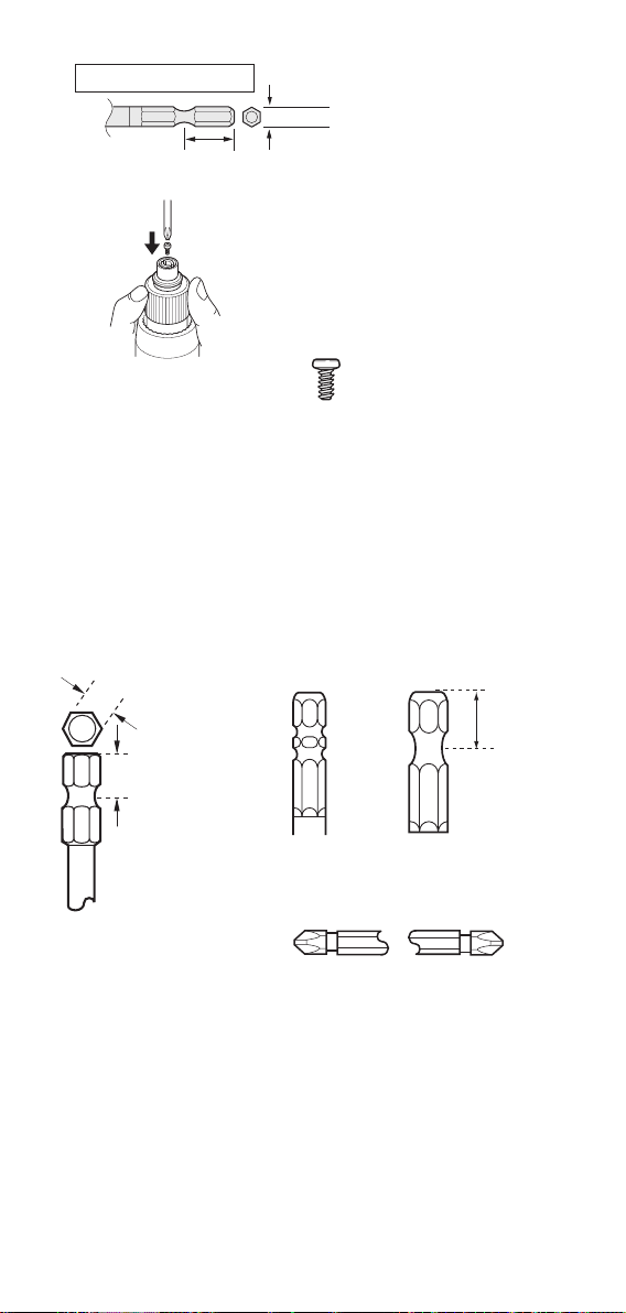
■Types of driver bits that can be used with the VZ-
1812, VZ-1820, VZ-3007 and VZ-3012 series
Caution
60mm
16mm
5mm wide
5mm wide Hexagonal W Bit
(Caution)
When using the HIOS
driver bit ∅5 or 5 mm
wide Hexagonal W Bit,
check that the Phillips
adjustment screw
within the driver body
has not been tightened.
*If the Phillips adjustment screw
has been tightened the driver bit
may drop out.
Joint shaft collar
HIOS Driver Bit H5
H5 (∅5)
- 13 -
■Types of driver bits that can be used with the VZ-
4504, VZ-4504PS, VZ-4506 and VZ-4506PS.
• For safe operation use bits conforming to the standards
indicated in the diagram on the left below. The diagrams on
the right indicate bits that cannot be used with the Screw
driver.
14mm
5mm wide
5mm wide Hexagonal Bit
6.35
9.0
W bit
9.0
Bits whose
length from the
point to the
bearing groove
is not 9 mm.
Double recess
bearing groove
Use size 6.35
mm hexagonal
bits whose
length from the
point to the
bearing groove
are 9 mm.
(Caution)
When using the 5 mm wide
Hexagonal W Bit, tighten
the Phillips adjustment
screw (supplied screw)
tightly into the driver bit
chuck.
* If the Phillips adjustment screw is
not tightened for enough, the driver
bit will not be locked and may result
in unreliable screw fastening.
Use the Phillips
adjustment screw (M 2.6)
Tighten the Phillips
adjustment screw properly
Bits for use Bits unsuitable for driver

- 14 -
■How to adjust the torque
The Torque Adjusting Scale does not indicate the torque value
directly. The torque value of each scale is indicated by the
Approximate Guidance of Output Torque on P.14.
Sometimes, there may be dierence between xed value
and actual tightening torque by the condition of screw and
materials. Please use this Approximate Guidance to get the
approximate torque value.
(1) Referring the Approximate Guidance of Output Torque,
decide the position of Torque Adjusting Nut in the Torque
Adjusting Scale.
(2) Rotate the Torque Adjusting Nut and set the right upper of
decided graduation.
(3) Start the motor and tighten the screw. Check the condition
of tightening screw.
(4) If the tightening is not enough, tighten up the Torque
Adjusting Nut.
In case of opposite, loosen it. Repeating the adjustment, nd
the most suitable point.
• The VZ-1510 (VZ-1510PS) Electric Screwdriver have ‘Double
nut system’ (Nut xing ring and Torque adjusting nut) to avoid
loosening from shock or vibration to the driver. To adjust those
two nuts, follows (1) to (3) steps below.
(1) At rst, stop the Nut xing ring upper
surface to t the graduation, if you
want to adjust.
(2) Then turn the Torque adjusting nut so
as to push up the Nut xing ring.
(3) Lastly, to avoid the loosening of the
Torque adjusting nut strongly fasten
the Nut xing ring by holding the
Torque adjusting nut.
■We recommend to use the HIOS Torque meter Tools
to set the torque of Screw Driver or to check the
torque of screw. (HP, HDP series)
• To set the torque of Electric Screw Driver or to check the
measurement tools (Torque Driver, etc.) ∙∙∙ HP Type
• To measure the loosening torque or tightening torque ∙∙∙HDP
Type
- 15 -
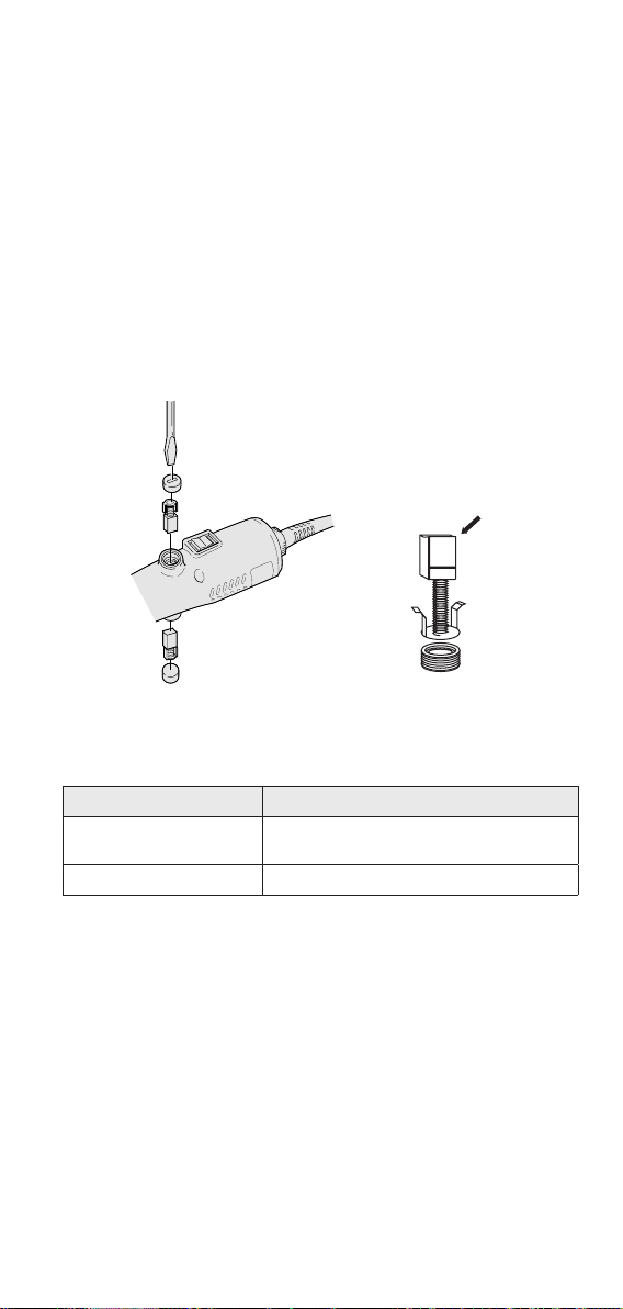
■How to change the Carbon Brush
(Caution)
Whenever changing the Carbon Brush, AC plug should be
unplugged.
• Unscrew the slotted Carbon Brush Cap by Slotted Screw ( - )
Driver and remove it.
• When the Carbon Brush Cap is changed, pay attention to the
direction of brush surface (concavity). Insert the Brush to t its
surface to the Commutator's.
• Slot on the side of Carbon Brush indicates Limit for Use.
Change the Brush when it is abraded over the Slot. To keep the
good condition, we recommend to change it earlier.
• Be careful so as not to tighten the Carbon Brush Cap too
strongly.
Concave
■List carbon brushes and compatible screwdriver (1
pair = 2pcs)
Applicable models Oder Cord
VZ-1510
(including PS type)
VZ-1820, VZ-3012, VZ-3007, VZ-4506
(including PS type)
ACL10-0490 VZ18-0480
- 16 -
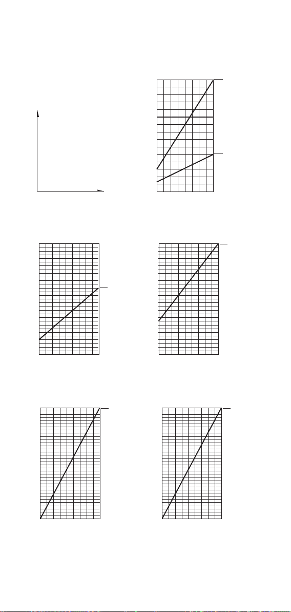
■Approximate Guidance of Output Torque
Torque Scale
Torque Scale
0.5
1.5
2
2.5
3
1
123 4 5 6 7 8 9 10
1.5
1
2.5
3
3.5
4
4.5
2
1 2 3 4 5 6 7 8 9 10
VZ-4506
VZ-4506PS
VZ-1820
VZ-1820PS
Y
W
0.5
1
1.5
1 2 3 4 5 6 7 98
N·m
VZ-1510
VZ-1510PS
Torque Scale
S
R
S: Silver
R: Red
Bl: Black
W: White
Y: Yellow
Torque Adjustment Scale
(Upper edge of Nut)
N·m
Torque Scale
0.5
1.5
2
2.5
3
1
123 4 5 6 7 8 9 10
VZ-3012
VZ-3012PS
Bl
Torque Scale
Torque Scale
0.5
1.5
2
2.5
3
1
123 4 5 6 7 8 9 10
VZ-3007
VZ-3007PS
1.5
1
2.5
3
3.5
4
4.5
2
1 2 3 4 5 6 7 8 9 10
VZ-4504
VZ-4504PS
Bl
Y
Torque Scale
0.5
1.5
2
2.5
3
1
123 4 5 6 7 8 9 10
VZ-1812
VZ-1812PS
W

- 17 -
Torque Scale
Torque Scale
0.5
1.5
2
2.5
3
1
123 4 5 6 7 8 9 10
1.5
1
2.5
3
3.5
4
4.5
2
1 2 3 4 5 6 7 8 9 10
VZ-4506
VZ-4506PS
VZ-1820
VZ-1820PS
Y
W
0.5
1
1.5
1 2 3 4 5 6 7 98
N·m
VZ-1510
VZ-1510PS
Torque Scale
S
R
S: Silver
R: Red
Bl: Black
W: White
Y: Yellow
Torque Adjustment Scale
(Upper edge of Nut)
N·m
Torque Scale
0.5
1.5
2
2.5
3
1
123 4 5 6 7 8 9 10
VZ-3012
VZ-3012PS
Bl
Torque Scale
Torque Scale
0.5
1.5
2
2.5
3
1
123 4 5 6 7 8 9 10
VZ-3007
VZ-3007PS
1.5
1
2.5
3
3.5
4
4.5
2
1 2 3 4 5 6 7 8 9 10
VZ-4504
VZ-4504PS
Bl
Y
Torque Scale
0.5
1.5
2
2.5
3
1
123 4 5 6 7 8 9 10
VZ-1812
VZ-1812PS
W


1-35-1 Oshiage, Sumida-ku Tokyo, Japan 131-0045
TEL: 81-3-6661-8821 FAX: 81-3-6661-8828
HIOS Inc.
This manual suits for next models
14
Table of contents
Other HIOS Power Tools manuals


