Clemco CLASSIC BLAST MACHINE User manual

CLASSIC BLAST MACHINE
2 CUFT TO 20 CUFT CAPACITY
WITH PNEUMATIC TLR REMOTE CONTROLS
O. M. 22501
DATE OF ISSUE: 02/99
REVISION: I, 02/18
© 2018 CLEMCO INDUSTRIES CORP.
One Cable Car Dr.
Washington, MO 63090
Phone (636) 239-4300
Fax (800) 726-7559
www.clemcoindustries.com
Do not use this
equipment before
READING this MANUAL
and UNDERSTANDING
its contents.
These WARNINGS are
included for the health
and safety of the
operator and those in
the immediate vicinity.
Electronic files include
a Preface containing
the same important
information as in the
orange cover.
WARNING

CLASSIC BLAST MACHINE with TLR-100/300 REMOTE CONTROLS Page 1
© 2018 CLEMCO INDUSTRIES CORP. www.clemcoindustries.com Manual No. 22501, Rev. I 02/18
1.0 INTRODUCTION
1.1 Scope of manual
1.1.1 This manual covers installation, operation,
maintenance, troubleshooting, and replacement parts for
Clemco blast machines raging in size from 2 cuft
through 20 cuft with TLR-100/300, and TLR-100/300D
pneumatic remote controls, and with standard FSV
abrasive metering valve. These instructions also contain
important safety information required for safe operation
of the machine. The following separate instruction
manual is provided for the remote control handle.
RLX control handle .............................Manual No. 10574
NOTE: Separate operation instructions are included
when alternate valves are provided.
The optional abrasive cutoff system (ACS) uses a
pneumatically operated abrasive metering valve.
Separate operating instructions are included for the
metering valve when an ACS system is provided.
1.1.2 This manual contains important safety
information. All operators and personnel involved with
the abrasive blast process must read and understand
the contents of these instructions, including the orange
cover. It is equally important that the operator is trained
and qualified to safely operate the blast machine, remote
controls, and all other equipment used with the blast
machine.
1.1.3 All personnel involved with abrasive blasting
must be aware of the hazards associated with abrasive
blasting. The Clemco booklet Abrasive Blasting Safety
Practicesis included with every blast machine; it
contains important safety information about abrasive
blasting that may not be included in equipment operation
manuals. The booklet is available in both English and
Spanish; to request copies, email
1.2 Safety Alerts
1.2.1 Clemco uses safety alert signal words, based on
ANSI Z535.4-2011, to alert the user of a potentially
hazardous situation that may be encountered while
operating this equipment. ANSI's definitions of the signal
words are as follows:
This is the safety alert symbol. It is
used to alert you to potential physical
injury hazards. Obey all safety
messages that follow this symbol to
avoid possible injury or death.
NOTICE
Notice indicates information that is considered
important, but not hazard-related, if not
avoided, could result in property damage.
CAUTION
Caution indicates a hazardous situation that, if
not avoided, could result in minor or moderate
injury.
WARNING
Warning indicates a hazardous situation that, if
not avoided, could result in death or serious
injury.
DANGER
Danger indicates a hazardous situation that, if
not avoided, will result in death or serious
injury.
1.3 Table of Contents
SUBJECT LOCATION
INTRODUCTION ........................................................ 1.0
Scope of Manual .........................................................1.1
Safety Alerts ...............................................................1.2
Table of Contents .......................................................1.3
Components and Operating Principles ....................... 1.4
Components .............................................................1.4.1
Blast Machine...........................................................1.4.2
Remote Controls ......................................................1.4.3
Abrasive Cutoff System (ACS) Option .....................1.4.4
Electric Control Alternate .........................................1.4.5
Abrasive.......................................................................1.5
INITIAL SETUP ..........................................................2.0
Storage Hopper ..........................................................2.1
Pressure Regulator to Reduce Blast Pressure ..........2.2
Setup for Multiple Blast Machine Operating
from a Common Compressed-Air Supply ................2.3
Install Optional Air Filter (Moisture Separator) ...........2.4
Compressed-Air Supply Hose Connection .................2.5
Blast Hose and Remote Control Hose Connections ..2.6
Additional Setup for ACS Option ................................2.7

CLASSIC BLAST MACHINE with TLR-100/300 REMOTE CONTROLS Page 2
© 2018 CLEMCO INDUSTRIES CORP. www.clemcoindustries.com Manual No. 22501, Rev. I 02/18
OPERATION .............................................................. 3.0
Transporting and Moving ........................................... 3.1
Setup for Operation .................................................... 3.2
Blasting Attire ............................................................. 3.3
Pressurize Blast Machine to Start Blasting ................ 3.4
Operation and Function of the Choke Valve .............. 3.5
Operation of Optional Abrasive Cutoff Switch (ACS) ... 3.6
Stop Blasting .............................................................. 3.7
Loading Abrasive into the Blast Machine ................... 3.8
Emptying the Machine of Abrasive ............................. 3.9
Shutdown .................................................................3.10
ADJUSTMENTS ........................................................ 4.0
Adjust Abrasive Flow .................................................. 4.1
PREVENTIVE MAINTENANCE ................................. 5.0
Daily or More Frequent Inspection ............................. 5.1
Weekly Inspection ...................................................... 5.2
Monthly Inspection ..................................................... 5.3
Periodic Inspection ..................................................... 5.4
Lubrication .................................................................. 5.5
SERVICE MAINTENANCE ........................................ 6.0
Removing Damp Abrasive from the Blast Machine ... 6.1
Clearing Obstructions in the Abrasive Metering
Valve and Blast Machine ........................................ 6.2
Inlet Valve ................................................................... 6.3
Piston Outlet Valve ..................................................... 6.4
Diaphragm Outlet Valve ............................................. 6.5
Abrasive Trap ............................................................. 6.6
Replacing the Pop-Up Valve ...................................... 6.7
Replacing the Pop-Up Seal ........................................ 6.8
Exhaust Muffler .......................................................... 6.9
Remove and Install Reusable Control Hose Fittings . 6.10
RLX Control Handle .....Refer to RLX Manual No. 10574
TROUBLESHOOTING ............................................... 7.0
Neither Abrasive Nor Air Exits Nozzle While
Machine is Under Pressure ........................................ 7.1
Air Only (No Abrasive) Exits the Nozzle .................... 7.2
Heavy Abrasive Flow .................................................. 7.3
Abrasive Surging ........................................................ 7.4
Intermittent Abrasive Flow .......................................... 7.5
Blast Machine Does Not Pressurize .......................... 7.6
Blast Machine Does Not Depressurize or
Depressurizes Too Slowly ....................................... 7.7
Outlet Valve Leaks Air During Blasting ...................... 7.8
Optional ACS Feature .....................................................7.9
No Abrasive When ACS Toggle is Moved
ON, Blast Mode ......................................................7.9.1
Abrasive Does Not Stop When ACS Toggle
is Moved OFF, Blowdown Mode ...........................7.9.2
REPLACEMENT PARTS ........................................... 8.0
Blast Machine Accessories ........................................ 8.1
Hose-Safety Accessories ........................................... 8.2
TLR-100/300 Remote Control Systems...................... 8.3
Exhaust Muffler .......................................................... 8.4
Blast Machine and Accessories ................................. 8.5
FSV Abrasive Metering Valve ....................................8.6
Remote Control System Replacement Parts ............. 8.7
ACS System Replacement Parts ............................... 8.8
1-1/2" Inlet Valve ........................................................ 8.9
1" Inlet Valve ............................................................ 8.10
1" Piston Outlet Valve ...............................................8.11
1" Diaphragm Outlet Valve .......................................8.12
Abrasive Trap ...........................................................8.13
RLX Control Handle .............Refer to Manual No. 10574
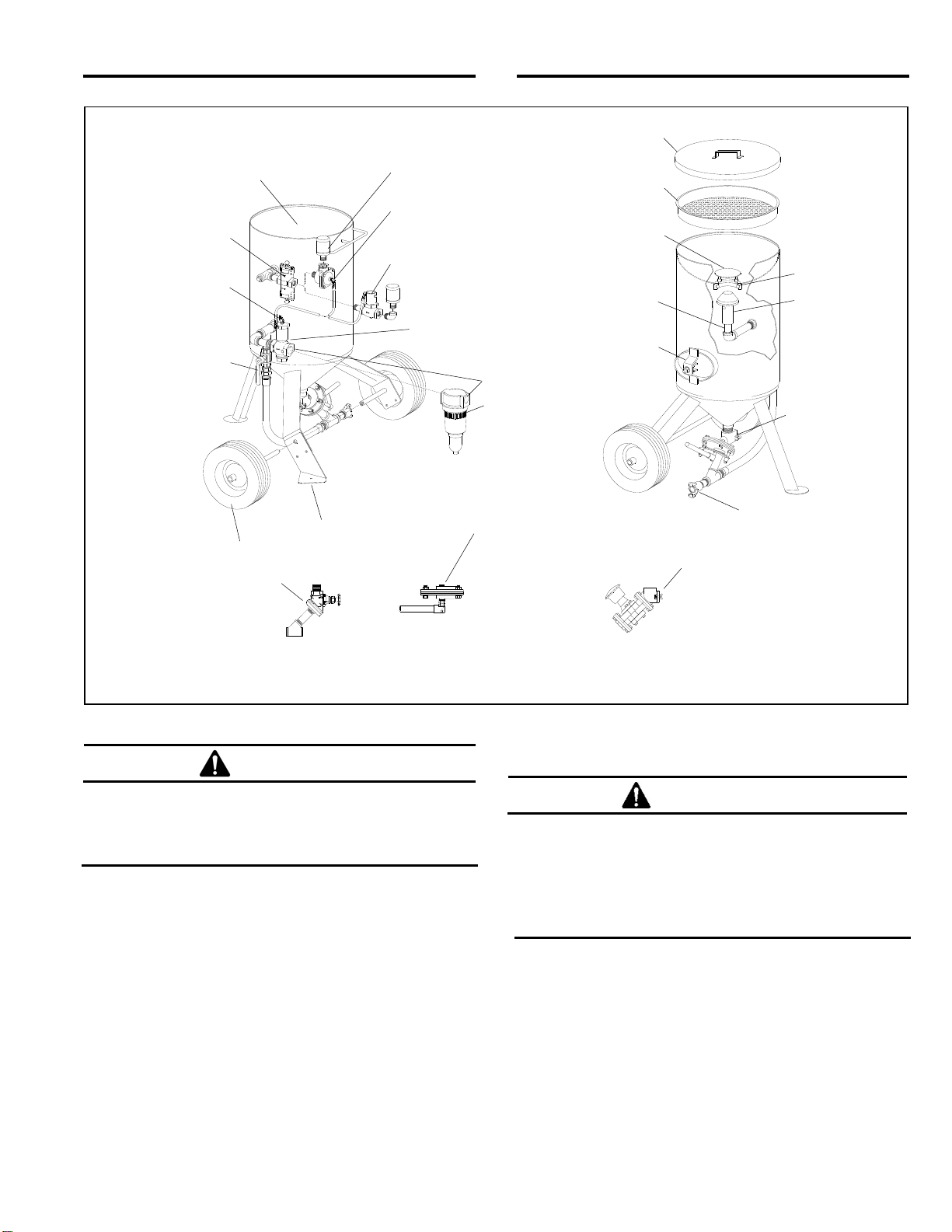
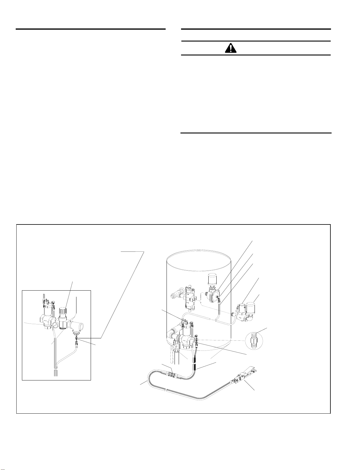
1.4 Components and Operating Principles
1.4.1 Components
1.4.1.1 The primary components of the blast machine
and the remote control system are shown in Figure 1.
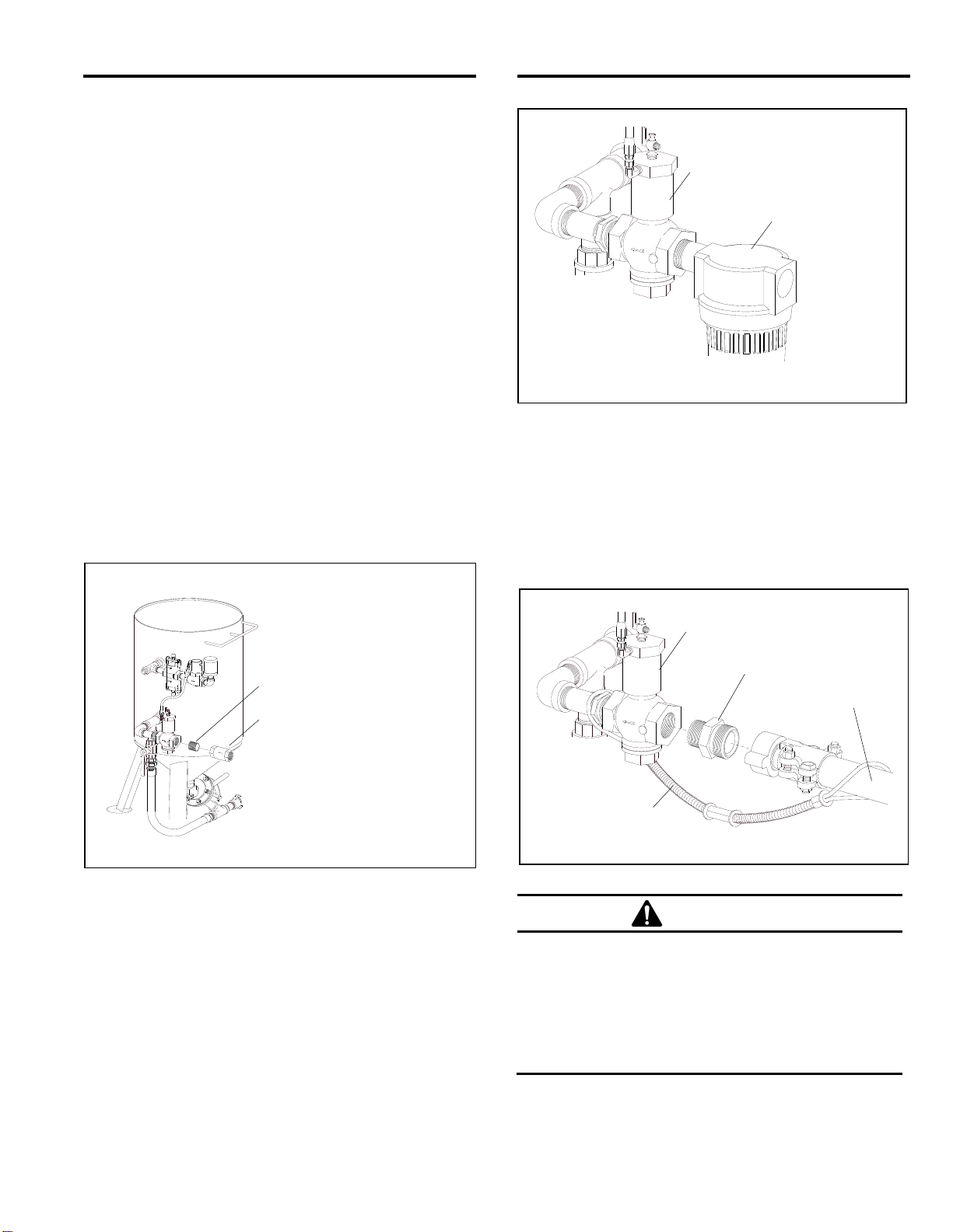
Additional components of the remote controls are shown
in Figure 2. Additional parts used with optional ACS
system are shown in Figure 9.
1.4.2 Blast Machine
1.4.2.1 Clemco certifies its blast machines (pressure
vessels) to conform to the ASME (American Society of
Mechanical Engineers) Boiler and Pressure Vessel
Code, Section VIII, Division 1. It is the owner’s
responsibility to maintain the integrity of the vessel in
accordance with state regulations. Regulations may
include regular inspection and hydrostatic testing as
described in National Board inspection code and
jurisdictional regulations and/or laws.
WARNING
Welding, grinding, or drilling on the blast
machine could weaken the vessel.
Compressed-air pressure can cause a
weakened blast machine to rupture, resulting in
death or serious injury. Welding, grinding, or
drilling on the vessel without a National Board
R stamp voids the Clemco ASME certification.
1.4.2.2 All welding repairs to the vessel must be
performed by certified welders at shops holding a
National Board R Stamp. Welding performed by any
welder not properly qualified per the ASME code voids
the Clemco ASME certification.
1.4.2.3 Do not exceed the maximum working pressure
rating (PSI) of the blast machine. The maximum
pressure rating is stamped into the ASME nameplate,
which is welded to the side of the vessel.

CLASSIC BLAST MACHINE with TLR-100/300 REMOTE CONTROLS Page 3
© 2018 CLEMCO INDUSTRIES CORP. www.clemcoindustries.com Manual No. 22501, Rev. I 02/18
Figure 1
WARNING
Excessive compressed-air pressure can cause
a blast machine to rupture. To prevent serious
injury or death, do not exceed the rated
pressure of the blast machine.
1.4.2.4 OSHA does not require pressure relief valves on
blast machines when air compressors supplying air to
the blast machines are built to American Society of
Mechanical Engineers Boiler and Pressure Vessel Code,
Section VIII, Division 1 and comply with OSHA
regulation 29 CFR 1910.169, which refers to the ASME
code when describing the necessity of pressure relief
valves on compressed air equipment. DO NOT operate
blast machines with air compressors that are not
equipped with properly functioning pressure relief valves
with maximum pressure less than or equal to the
maximum allowable working pressure (MAWP) stamped
on the vessel nameplate.
1.4.3 Remote Controls
WARNING
Never modify or substitute remote control
parts. Parts from other manufacturers are not
compatible with Clemco equipment. If ANY part
of the remote control system is altered,
involuntary activation can occur, causing
serious injury.
1.4.3.1 A remote control system is an OSHA-required
safety device; it is required when an operator mans the
nozzle. The remote controls allow the blast operator to
pressurize the machine to start blasting and
depressurize it to stop blasting.
1.4.3.2 The control handle, located near the blast nozzle,
is the activator for the remote control system. When the
operator intentionally or unintentionally removes
handheld pressure from the control handle, the machine
depressurizes and blasting stops. The remote control
Alternate 22845 MQV
Manual Quantum
All-Media Metering Valve
Concave Filling Head
Safet
y
Petcock
Abrasive Trap
Choke Valve
(Shown open)
O
p
tional Cove
r
O
p
tional Umbrella
Po
p
-U
p
Valve
Ins
p
ection Doo
r
*O
p
tional Screen
Po
p
-U
p
Seal
Po
p
-U
p
Guide
FSV Abrasive
Metering Valve
Quick Coupling
(Blast hose connector)
Alternate 04321 MPV,
Manual Pinch-Tube
Metering Valve
(For use with steel grit)
05680 LPV
Lo-Pot Metering Valve
Used on Lo-Pot machines
Leg Pad Option
Wheel Option
Inlet Valve
Piston Outlet Valve
Diaphragm Outlet Valve
Exhaust Muffler
Compressed-Air Inlet
Air Filter
(*optional accessory)
* These accessories are included with blast machine systems.

CLASSIC BLAST MACHINE with TLR-100/300 REMOTE CONTROLS Page 4
© 2018 CLEMCO INDUSTRIES CORP. www.clemcoindustries.com Manual No. 22501, Rev. I 02/18
system "fails to safe", which means when an interruption
in the control-air circuit occurs for reasons such as a
break in the line, the compressor stops running, or if the
operator drops the blast hose, the remote control
deactivates the blast machine and blasting stops.
1.4.3.3 Components of the TLR remote control system
are shown in Figures 1 and 2. They include the inlet
valve piston or diaphragm outlet valve (the piston valve
is used in most applications, the diaphragm valve is
recommended for use with fine mesh or aggressive
abrasive), RLX control handle, 50-ft. and 5-ft. long
twinline control hoses, 2 control hose unions, and an 18-
inch-long interconnecting hose.
1.4.3.4 TLR remote controls are pressure-release-style
systems, which control the pressurization and
depressurization of the blast machine. Pressurization,
which starts blasting, occurs when the control handle is
pressed, and depressurization, which stops blasting,
occurs when the handle is released.
WARNING
Moist air that freezes can cause blockage at the
control handle or in the control lines. Blockage
can cause involuntary activation of the remote
controls or prevent the controls from
deactivating upon release of the control handle.
This situation can result in serious injury or
death. If remote controls are operated in
freezing or near-freezing weather, install a
Clemco Antifreeze Injector, stock no. 05537, on
the remote control air-supply line.
1.4.3.5 Clemco remote controls operate pneumatically
on a return-air principle. A stream of control air travels
from the orifice on the inlet valve, down the outbound
twinline (shown shaded1in Figure 2) and escapes
through the opening located under the control handle
lever. The normally closed inlet valve remains closed,
and the normally open outlet valve remains open. As
long as air escapes through the handle’s opening, the
remote control system remains inactive. When the
Figure 2
1 Shading indicates the outbound line; it does not matter which side of the twinline is used for the outbound and return line
When using a regulator to reduce
blast pressure, relocate the orifice
upstream of the regulator and plug
the orifice port in the inlet valve.
Piston Outlet Valve
Pressure Regulator
Orifice Fittin
g
Diaphragm Outlet Valve
5-Ft. Twinline Hose (Outbound side)
RLX Control Handle
Muffler (accessory)
not included with the remote
control system.
3/16" x 18-Inch Hose
Safety Petcock
Elbow Adaptor
Compressed-Air Inlet
Twinline Hose Unions (2)
50-Ft. Twinline Hose
(Inbound side of twinline)
Orifice Fitting
1/16" orifice as seen
from backside of fitting

CLASSIC BLAST MACHINE with TLR-100/300 REMOTE CONTROLS Page 5
© 2018 CLEMCO INDUSTRIES CORP. www.clemcoindustries.com Manual No. 22501, Rev. I 02/18
operator presses the control lever, a rubber button
seals the opening, and outbound air returns through
the inbound line to open the inlet valve and close the
outlet valve. This action pressurizes the blast machine
and begins the blasting. Releasing the handle
exhausts the control air, which causes the inlet valve to
close and the outlet valve to open to depressurize the
blast machine and stop the blasting.
1.4.4 Abrasive Cutoff System (ACS) Option
1.4.4.1 The abrasive cutoff switch is mounted on the
control handle. It closes the metering valve so that air
alone without abrasive exits the nozzle. This feature is
used to clear the blast hose and to blowdown the blast
surface.
NOTE: The ACS feature requires a pneumatically
operated abrasive metering valve. It is not available
on Lo-Pot blast machines, which do not have
adequate clearance for the metering valve.
1.4.4.2 Parts used with an optional ACS are shown in
Figure 9. In addition to the standard remote controls, an
ACS also includes a 50-ft. single-line hose, an additional
18-inch-long interconnecting hose, an RLX control
handle with ACS air switch assembly, and a
pneumatically operated metering valve. The metering
valve supplied with the system may differ from the one
shown. A separate owner’s manual is supplied with an
alternate metering valve.
1.4.5 Electric Control Alternate
1.4.5.1 Electric remote controls (electro-pneumatic) are
recommended when the nozzle and remote control
handle are farther than 100 feet from the blast machine.
Pressure drop of pneumatic systems over longer
distances increases response time, which prevents fast,
safe operation. Contact your local Clemco Distributor for
additional information.
1.5 Abrasive
WARNING
Abrasives and dust from blasting may contain
toxic materials (e.g., lead paint, silica) that are
hazardous to workers. Before blasting, obtain a
safety data sheet (SDS) for the blast abrasive
and identify all substances removed by the
blasting process.
• Silica sand (crystalline) can cause silicosis,
lung cancer, and breathing problems in
exposed workers.
• Slags can contain trace amounts of toxic
metals such as arsenic, beryllium, and
cadmium and have the potential to cause
lung disease.
NO DUST IS SAFE TO BREATH. DUST
PRODUCED FROM ANY ABRASIVE OR FROM
THE BLASTING PROCESS CAN CAUSE
SERIOUS LUNG DISEASE AND DEATH WHEN
INHALED. It is the employer’s responsibility to
train employees to identify hazardous
substances and to provide suitable policies,
procedures, monitoring, recordkeeping, and
personal protective equipment.
NOTE: Use only abrasives specifically manufactured
for blasting that are compatible with the surface
being blasted. Abrasives produced for other
applications may be inconsistent in size and shape
and produce an unsatisfactory finish, contain
particles that could jam the abrasive metering valve,
or cause irregular wear.
1.5.1 Selection of blasting abrasive can play a
significant part in worker health risk, job productivity, and
maintenance of the blast machine. DO NOT USE
abrasives containing more than 1% crystalline (free)
silica. Obtain safety data sheets (SDS) for the blasting
abrasive prior to blasting, paying particular attention to
worker health risks and presence of any hazardous/toxic
substances.
1.5.2 Abrasive Mesh Size
1.5.2.1 The choice of abrasive mesh size depends on
the desired profile, cleaning rate, nozzle orifice size, and
availability of clean, dry air. Generally, larger, denser
abrasives provide a deeper profile, while smaller
abrasives clean faster. Most abrasive blasting is done
with abrasive sizes between 16 and 80 mesh. Larger
sizes may be used if the nozzle orifice is large enough to
prevent particles to pass without jamming. Finer

CLASSIC BLAST MACHINE with TLR-100/300 REMOTE CONTROLS Page 6
© 2018 CLEMCO INDUSTRIES CORP. www.clemcoindustries.com Manual No. 22501, Rev. I 02/18
abrasives are especially sensitive to moisture and
require very dry air to prevent bridging in the metering
valve.
1.5.3 Sand: Sand should never be used because of
the respiratory hazards associated with abrasives
containing free silica.
1.5.4 Slag: Slag abrasives are compatible with the
blast machine fitted with an FSV metering valve or any
of the alternate metering valves. Obtain safety data
sheet (SDS) to identify hazardous substances.
1.5.5 Steel: Steel shot and steel grit may be used with
machines fitted with an alternate Quantum or manual
PVR pinch-tube metering valve. Alternate valves are
shown in Section 8.5. Shot applications may require the
use of a pneumatically operated metering valve, such as
the Sentinel or Auto-Quantum, to prevent surging at
startup.
1.5.6 Silicon carbide, aluminum oxide, and garnet:
These are the most aggressive, high-volume abrasives
used in the blasting industry. These abrasives may be
used, but the service life of any equipment components
which come in contact with the abrasive will be reduced.
Use a nozzle lined with boron carbide with these
abrasives.
1.5.7 Glass bead: Most beads are treated to ensure
free-flow operation even under moderately high-
humidity. Glass beads subjected to excessive moisture
may be reused after thorough drying and breaking up of
any clumps. Clean, dry air is a necessity. Glass bead
applications may require the use of a pneumatically
operated metering valve, such as the Sentinel or AQV
Auto-Quantum, which can help to prevent surging at
startup.
1.5.8 Lightweight media: Plastic media and most
agricultural media may be used occasionally in a
standard blast machine. Exclusive use of plastic, and
some other lightweight media, requires a blast machine
with a 60oconical bottom for continuous, uninterrupted
media flow.
2.0 INITIAL SETUP
WARNING
Clemco supplies an exhaust muffler with all
blast machines of 2 cuft capacity and larger.
The muffler reduces exhaust noise and
prevents abrasive from exhausting upward or
sideways into the air. When the blast machine
is depressurized, the muffler body pops up to
diffuse the air and abrasive. When the machine
is fully depressurized, the muffler body drops,
permitting trapped abrasive to empty. For the
muffler to work properly, it must be installed
with the body facing up, as shown in Figure 1.
If an application requires the muffler to be
removed, the exhaust piping must be plumbed
to direct exhausting air in a direction that
ensures no persons will be exposed to high
velocity air and abrasive, which escapes when
the blast machine is depressurized.
2.1 Storage Hopper
2.1.1 When a storage hopper is installed above the
blast machine, an umbrella mounted above the pop-up
opening is required. Refer to Section 8.5, Item 22 for
optional bolt-on umbrella.
2.2 Installation of a Pressure Regulator to
Reduce Blast Pressure
2.2.1 When installing a pressure regulator to reduce
blast pressure below 60 psi (80 psi when using an ACS),
install a tee upstream of the regulator as shown in the
insert in Figure 2, relocate the orifice to the tee, and plug
the orifice port in the inlet valve. This allows the
pneumatic control circuit to operate at line pressure.
2.3 Setup for Multiple Blast Machines Operating
From a Common Compressed-Air Supply
NOTICE
If multiple machines are operating from a
common compressed-air supply and a machine
is under pressure when another machine is
pressurized, the sudden, increased demand for
air could reverse air flow from the machine that
is under pressure and contaminate the
compressed-air supply with abrasive-laden air.
Install check valves at the piping inlet to
prevent the reversal of air.

CLASSIC BLAST MACHINE with TLR-100/300 REMOTE CONTROLS Page 7
© 2018 CLEMCO INDUSTRIES CORP. www.clemcoindustries.com Manual No. 22501, Rev. I 02/18
2.3.1 Where multiple blast machines are operating
from a single air source, install a ball cone check valve
at the air supply on each machine. Refer to the
illustration in Figure 3 to install a check valve on a blast
machine.
2.3.2 If the machines are placed close together, use a
receiver tank or manifold and run separate air lines from it
to each machine. The check valves may be located on the
receiver tank outlets if the air line goes directly to the blast
machine and nowhere else.
NOTE: Do not use a swing check valve, as the swing
gate may break in blast machine applications. When
installing the valve, make sure the directional arrow is
pointing in the direction of the air flow (toward the
machine).
2.3.3 Use a Clemco ball cone check valve shown
below. A smaller-size valve could restrict air movement
and reduce nozzle pressure.
TLR-100 with 1-NPT inlet valve
use 1-1/4-NPT check valve ......... Stock No. 02088
TLR-300, with1-1/2-NPT inlet valve
use 1-1/2-NPT check valve ......... Stock No. 02296
Figure 3
2.4 Install Optional Air Filter
(Moisture Separator) - Figure 4
The filter is included with blast machine systems.
2.4.1 Install a compressed-air filter to the inlet valve
as shown in Figure 4. It is recommended that a filter be
installed at this location to remove moisture from air
before it enters the machine. If problems with moisture
persists after installing the filter, a dryer or aftercooler
may be required in the air-supply line.
Figure 4
2.5 Compressed-Air Supply Hose Connection
2.5.1 Apply thread sealant to the male pipe threads of
an air fitting that is compatible with the air supply hose
fitting, as noted in Section 2.5.2, and install it onto the inlet
valve or optional air filter located at the blast machine
inlet, as shown in Figure 5. The style of connection shown
in Figure 5 is for reference only.
Figure 5
WARNING
Hose disconnection while under pressure can
cause serious injury or death. Use safety lock
pins or safety wire to lock twist-on (claw-type)
couplings together and prevent accidental
separation while under pressure and use
safety cables to prevent hose from whipping
should separation occur.
2.5.2 Attach an air line from the compressor to the
hose fitting installed on the blast machine inlet. For best
blasting performance, refer to the table in Figure 6 for
Ball Cone Check Valve
Close Nipple
Use a standard 1-1/4" x 1"
pipe bushing, Clemco Stock
No. 01804, when installing on
a TLR-100, 1" inlet valve.
Inl
et
V
a
lv
e
Air H
ose
A
daptor
Air Supply Hose
Safety cable
Inl
et
V
a
lv
e
Optional Air Filter

CLASSIC BLAST MACHINE with TLR-100/300 REMOTE CONTROLS Page 8
© 2018 CLEMCO INDUSTRIES CORP. www.clemcoindustries.com Manual No. 22501, Rev. I 02/18
the minimum recommended hose size based on the
nozzle orifice size. A smaller diameter hose could result
in a reduction in nozzle pressure.
AIR LINE RECOMMENDATIONS
BASED ON NOZZLE SIZE
Nozzle
Orifice Size
Recommended Air Supply Line
No. 3, 3/16" 3/4" ID or larger
No. 4, 1/4" 1" ID or larger
No. 5, 5/16" 1-1/4" ID or larger
No. 6, 3/8" 1-1/2" ID or larger
No. 7, 7/16" 2" ID or larger
No. 8, 1/4" 2" ID or larger
Refer to the compressed-air and abrasive
consumption table in Figure 10 for approximate air
consumption.
Figure 6
2.6 Blast Hose and Remote Control Hose
Connections
NOTE: When installing the optional ACS feature,
refer to Section 2.7 for additional instructions.
WARNING
Where two or more blast machines are used in
close proximity, care must be taken when
tracing and connecting control lines and blast
hose. Cross connecting control hose or blast
hose could lead to serious injury, death, or
property damage from unintentional actuation
of a blast machine. To prevent cross
connecting blast hose and control hose, the
hoses should be of equal lengths and the hoses
and blast machine couplings clearly marked,
using optional hose identification kits, stock no.
15890 for use with two blast machines, or stock
no. 15891 for up to four machines. Mark each
hose and corresponding connection per the
instructions supplied with the kit and carefully
trace and verify each connection before
operating.
WARNING
Moist air that freezes can cause blockage at the
control handle or in the control lines. Blockage
can cause involuntary activation of the remote
controls or prevent the controls from
deactivating upon release of the control handle.
This situation could result in serious injury or
death. If remote controls are operated in
freezing or near-freezing weather, install a
Clemco Antifreeze Injector, stock no. 05537, on
the remote control air-supply line.
NOTE: Control hoses come with reusable hose ends.
Excess hose may be cut-to-fit and recoupled; refer to
Section 6.10.
2.6.1 Uncoil the blast hose and lay the 50-foot twinline
hose alongside it.
2.6.2 Band the control handle to the blast hose close
to the nozzle holder, as shown in Figure 7, using the two
nylon ties provided. After the control is firmly attached,
clip the tie ends to avoid snags or interference with the
operation of the control handle.
Figure 7
2.6.3 Attach the 50-foot twinline hose to the two
fittings on the control handle, as shown in Figure 8.
Either side of the hose can be attached to either fitting.
When using the ACS option, attach the single-line hose
noted in Section 2.7.
Figure 8
RLX Control Handle
Nozzle Holder
Blast Hose
Nylon Ties
Twinline Control Hose
Either side of the twinline
can attach to either fitting
on the control handle.

CLASSIC BLAST MACHINE with TLR-100/300 REMOTE CONTROLS Page 9
© 2018 CLEMCO INDUSTRIES CORP. www.clemcoindustries.com Manual No. 22501, Rev. I 02/18
NOTE: When attaching Clemco twinline hose to any
Clemco valves either side of the twinline hose can
be attached to either twinline fitting on the valve.
2.6.4 Working backward from the control handle, band
the twinline hose to the blast hose every four to six feet
and as close to the couplings as possible.
2.6.5 Temporarily connect the blast hose to the quick
coupling on the blast machine.
2.6.6 Attach the 5-foot twinline control hose to the inlet
valve as shown in Figure 2; one side of the hose
connects to the unused upper elbow, the other side to
the orifice fitting.
2.6.7 Connect the two hose unions to the other end of
the 5-foot hose and place the ends next to the blast-
hose coupling.
2.6.8 Band the 5-foot twinline control hose, on the blast
machine side of the unions, to the quick-coupling nipple.
2.6.9 Attach the 50-foot twinline hose to the unions on
the 5-foot twinline.
2.6.10 Make sure that all fittings are tight. Leaks cause
the system to malfunction.
NOTE: When removing the blast hose from the
machine, disconnect the 50-foot twinline hose at the
unions. When attaching the blast hose, make sure
all twinline fittings are tight. Make sure coupling
gaskets are in place and in good condition before
connecting the blast hose to the blast machine. Use
safety lock pins or safety wire to lock the couplings
together and prevent accidental separation while
under pressure, and use safety cables to prevent
hose from whipping should separation occur.
2.7 Additional Setup for ACS Option - Figure 9
2.7.1 Attach the 18-inch-long hose to the fitting on the
metering valve.
2.7.2 Attach the 50-foot-long single-line hose to the
ACS air switch assembly located on the RLX control
handle.
2.7.3 Use one of the three unions to attach the 50-foot
hose to the 18-inch-long hose.
Figure 9
18-Inch Hose
A
CS Switch
RLX Control Handle w/
A
CS Switch
Metering Valve
Valve may differ from that shown
50-Ft. Single-Line
A
CS Switch
Hose Unions

CLASSIC BLAST MACHINE with TLR-100/300 REMOTE CONTROLS Page 10
© 2018 CLEMCO INDUSTRIES CORP. www.clemcoindustries.com Manual No. 22501, Rev. I 02/18
3.0 OPERATION
3.1 Transporting and Moving
WARNING
Failure to observe the following warnings
before transporting or moving a blast machine
could result in serious injury or death:
Always empty the blast machine before
lifting or hoisting.
Never hoist the machine by the handle or
piping, or with a sling through the handle
or piping.
Always use lift equipment that is rated
higher than the weight of the machine and
accessories.
When transporting a machine on a pallet,
always securely attach the machine to a
sturdy pallet.
Always securely anchor the machine to the
transport vehicle.
Anyone using material handling equipment
to move, transport, or lift the machine must
be experienced, able to recognize and avoid
hazards associated with handling this type
of machinery, and able to safely operate the
equipment.
3.1.1 Transporting a Blast Machine
3.1.1.1 Always empty the machine before transporting.
Transporting a machine containing abrasive may
increase the weight to an unsafe handling limit and could
cause abrasive to settle in the piping.
3.1.2 Moving a Blast Machine
WARNING
Do not manually move the machine on an
incline, or on a slippery or irregular surface
that can cause the operator to slip or lose
balance. Sudden weight shifts when the
machine is tilted on an incline, and slipping or
tripping while moving the machine will cause
the operator to lose control of the machine,
causing severe injury and property damage.
WARNING
Never attempt to manually move a blast
machine when it contains abrasive. An empty
machine may be moved manually in a forward
direction on level flat surfaces.
3.1.2.1 An empty machine may be moved manually on
level flat surfaces by at least two people.
3.1.2.2 Slide the machine by pushing it in a forward
direction toward the wheels. To avoid tripping hazards
that may be out of view, do not back-up while moving
the machine.
3.1.2.3 The Clemco Mule (Stock No. 20331) is designed
to facilitate moving empty 2 cuft to 6 cuft capacity
Clemco blast machines. Contact a Clemco Distributor for
additional information.
3.2 Setup for Operation
3.2.1 Locate the compressor upwind from the blasting
operation to prevent contaminated air from entering the
compressor intake.
3.2.2 Attach an air line from the compressor to the air-
supply hose connector installed on the blast machine inlet.
For best blasting performance, use the minimum
recommended hose size as noted in Section 2.5, Refer to
the compressed-air and abrasive consumption table in
Figure 10 for approximate air consumption.
3.2.3 Make sure the coupling gaskets are in place and
in good condition before connecting the blast hose to the
quick coupling on the blast machine. NOTE: Spring-
lock pins are affixed to nylon couplings. When
connecting two nylon couplings together, make sure
the coupling spring-lock pins are at 180 degrees,
(Pins should enter the open hole of the adjoining
coupling.) The lock pins prevent accidental separation of
hose couplings during blasting. When connecting a nylon
coupling to a metal coupling, one affixed spring-lock pin
and one detached lock-pin, as shown in Section 8.2 is
used. When connecting two metal couplings together, use
two safety lock pins.
3.2.4 Make sure that all blast-hose couplings and
compressed-air supply hose connections are secured
with safety lock pins to lock the couplings together and
prevent accidental separation while under pressure, and
with safety cables to prevent hose from whipping should
separation occur. Lock pins and safety cables are listed
in Section 8.2.

CLASSIC BLAST MACHINE with TLR-100/300 REMOTE CONTROLS Page 11
© 2018 CLEMCO INDUSTRIES CORP. www.clemcoindustries.com Manual No. 22501, Rev. I 02/18
WARNING
Hose disconnection while under pressure can
cause serious injury or death. Use safety lock-
pins or safety wire to lock twist-on (claw-type)
couplings together and prevent accidental
separation while under pressure, and use
safety cables to prevent hose from whipping
should separation occur.
3.2.5 Attach the ends of the 50-foot twinline hose to
the unions previously connected to the 5-foot twinline
hose. Either side of the hose can be attached to either
fitting.
3.2.6 Check all fittings to make sure they are wrench-
tight. Leaks will cause the system to malfunction.
3.2.7 Make sure the choke valve is open; the valve is
open when the handle position is aligned with the piping,
as shown in Figure 10.
3.2.8 Close the abrasive metering valve. The FSV and
LPV (Lo-Pot valve) are closed when the handle is all the
way to either side of center; refer to Section 4.1. The
alternate MPV manual pinch-tube metering valve and
Quantum metering valves are closed when the metering
knob is turned fully clockwise. Manuals are provided with
alternate metering valves. NOTE: it is not necessary to
close the metering valve after the initial startup and
adjustment per Section 4.1.
Compressed-Air and Abrasive Consumption
Consumption rates are based on abrasives that weigh 100 pounds per cubic foot
Nozzle Pressure at the Nozzle (psi) Air, Power,
Orifice and Abrasive
Size (in.) 50 60 70 80 90 100 125 140 Requirements
26 30 33 38 41 45 55 61 Air (cfm)
No. 3 150 171 196 216 238 264 319 353 Abrasive (lbs/hr)
3/16" 6 7 8 9 10 10 12 14 Compressor (hp)
47 54 61 68 74 81 98 108 Air (cfm)
No. 4 268 312 354 408 448 494 608 676 Abrasive (lbs/hr)
1/4" 11 12 14 16 17 18 22 24 Compressor (hp)
77 89 101 113 126 137 168 186 Air (cfm)
No. 5 468 534 604 672 740 812 982 1085 Abrasive (lbs/hr)
5/16" 18 20 23 26 28 31 37 42 Compressor (hp)
108 126 143 161 173 196 237 263 Air (cfm)
No. 6 668 764 864 960 1052 1152 1393 1538 Abrasive (lbs/hr)
3/8" 24 28 32 36 39 44 52 59 Compressor (hp)
147 170 194 217 240 254 314 347 Air (cfm)
No. 7 896 1032 1176 1312 1448 1584 1931 2138 Abrasive (lbs/hr)
7/16" 33 38 44 49 54 57 69 77 Compressor (hp)
195 224 252 280 309 338 409 452 Air (cfm)
No. 8 1160 1336 1512 1680 1856 2024 2459 2718 Abrasive (lbs/hr)
1/2" 44 50 56 63 69 75 90 101 Compressor (hp)
For nozzle sizes 3/8" to 1/2", blast machines should be equipped with 1-1/4" or larger piping and inlet valve to prevent
pressure loss.
Air requirements were measured by a flowmeter under actual blasting conditions and are, therefore, lower than figures for
air alone, with no abrasive.
Horsepower requirements are based on 4.5 cfm per horsepower.
Figures are for reference only and may vary for different working conditions. Several variables, including metering valve
adjustments, can affect abrasive flow.
Figures show approximate compressed air and abrasive consumption when nozzles are new. Consumption will increase as
the nozzle wears.
Figure 10

CLASSIC BLAST MACHINE with TLR-100/300 REMOTE CONTROLS Page 12
© 2018 CLEMCO INDUSTRIES CORP. www.clemcoindustries.com Manual No. 22501, Rev. I 02/18
3.2.9 Make sure that the safety petcock located on the
inlet valve is open. Open position is when the lever is
aligned with the petcock, as shown in Figure 11.
Figure 11
3.2.10 Make sure the remote control handle lever is in
the up (no blast) position, as shown in Figure 12, and
that the handle lever and safety lock move freely.
Figure 12
WARNING
A separate manual is supplied with the remote
control handle. Do not operate the machine
before reading the remote control handle
operating instructions.
3.2.11 Make sure the rubber seal under the handle
lever does not seal the opening on the control handle,
unless the safety lever lock is intentionally folded down.
WARNING
Malfunctioning control handles can cause
unintentional actuation of a blast machine or
prevent a machine from deactivating upon
release. Malfunctioning control handles must
be taken out of service immediately and
repaired or replaced. Serious injury or death
could result from unintentional blasting.
3.2.12 Close the air valve on the compressor. Start the
compressor, and bring it to operating temperature and
pressure. The pressure must be more than 50 psi, but
must not exceed the blast machine’s rated pressure.
3.2.13 Slowly open the compressor air valve to
pressurize the air-supply line. Listen for open lines or air
leaks.
3.2.14 Load abrasive into the machine by following the
instructions in Section 3.8.
3.2.15 Do not allow anyone near the blast machine
except machine tenders who are appropriately attired in
approved personal protective equipment as noted in
Section 3.3.
WARNING
Everyone except for the blast operator or blast
machine tender must stay clear of the blast
machine. The machine tender or blast operator
may pressurize or depressurize the machine at
any time, which can cause abrasive to vent
under pressure, causing dust and toxins to
become airborne. Noise is produced by the
sudden release of compressed air when the
machine is pressurized or depressurized. These
conditions can cause injury. Both the operator
and machine tender must wear suitable
personal protective equipment including an
approved respirator, plus approved eye, face,
and hearing protection.
3.3 Blasting Attire
WARNING
Before blasting, test the coating and substrate
for toxic materials, such as lead or other heavy
metals, or asbestos. These hazards require
special measures to protect the operators and
the environment.
Obtain a safety data sheet (SDS) for the blast
abrasive to identify hazardous substances.
Silica sand (crystalline) can cause silicosis,
lung cancer, and breathing problems in
exposed workers. Slag abrasives may contain
trace amounts of toxic metals such as arsenic,
beryllium, and cadmium. Any abrasive dust has
potential to cause lung disease.
The lever lock must be folded down before the
control handle lever can be pressed.
L
e
v
e
r L
oc
k
Prevents control handle lever
from being pressed down to the
blast position.
Co
n
t
r
o
l H
a
n
d
l
e
L
e
v
er
Shown in the UP no-blast position.
Closed
Open

CLASSIC BLAST MACHINE with TLR-100/300 REMOTE CONTROLS Page 13
© 2018 CLEMCO INDUSTRIES CORP. www.clemcoindustries.com Manual No. 22501, Rev. I 02/18
Abrasive blasting operations can create high
levels of dust and noise. No dust is safe to
breathe. Abrasive blasting can produce harmful
dust. Failure to wear NIOSH-approved
respirators could result in serious lung disease
or death. The respirators must be properly fitted
and maintained NIOSH-approved, type-CE
supplied-air respirators approved for abrasive
blasting.
During abrasive blasting, abrasive particles and
dust in the area around the blast machine and
blast nozzle become airborne. Everyone
working in the vicinity of abrasive blasting must
wear properly maintained, NIOSH-approved,
respiratory protection and eye protection
appropriate for the job site hazards.
Loud noise generated by the use of
compressed air can cause hearing damage.
Everyone in the blasting area must wear
approved hearing protection.
It is the employer’s responsibility to train
employees to identify hazardous substances
and to provide suitable policies, procedures,
monitoring, recordkeeping, and personal
protective equipment.
3.3.1 Operators and anyone else who may be
exposed to the hazards generated by the blasting
process must wear appropriate protective gear,
including abrasive-resistant clothing, leather gloves, eye
and hearing protection, and a NIOSH-approved type-CE
supplied-air respirator.
3.3.2 Don protective blasting attire outside the blast
area in a clean nonhazardous environment, free of
contaminants, where the air is safe to breathe.
3.3.3 When finished blasting and after cleanup is
completed, remove the respirator and protective clothing
outside the respirator-use area in a clean environment
where the air is safe to breathe.
3.4 Pressurize Blast Machine to Start Blasting
3.4.1 Don all protective blasting attire per Section 3.3.
3.4.2 When the blast operator is ready to blast, the
operator or the machine tender must close the safety
petcock. Closing the petcock prepares the machine for
remote operation and activation by the control handle.
Air should be heard escaping from the opening under
the control handle lever but from nowhere else. The air
escaping at the control handle is an audible signal
meaning air is supplied to the blast machine, which will
activate when the control handle is pressed.
3.4.3 Hold the blast hose securely and point the
nozzle only toward objects intended to be blasted.
3.4.4 Fold down the safety lever lock and press the
remote control handle as shown in Figure 13. Within a
few seconds the pop-up valve will automatically close,
and the blast machine will pressurize to start blasting.
WARNING
Be prepared for the recoil from the blast hose.
Blasting should begin within a few seconds
after pressing the control handle lever.
Figure 13
WARNING
OSHA requires the use of remote controls on all
blast machines when an operator controls the
nozzle. To comply with OSHA regulations, the
remote control handle, which starts and stops
the flow of air and abrasive, must be held down
manually. Never tie down the control handle
lever or attempt to bypass any part of the remote
control system. Doing so will defeat the purpose
of the fail-to-safe feature of the remote control.
Serious injury or death could result from
uncontrolled blasting. Ref. 29 CFR 1910.244 (b).
3.4.5 If the abrasive metering valve is closed as
instructed, only air will exit the nozzle. Adjust abrasive
flow per Section 4.1.
Handle locked up
Fold lever lock down
Press control handle
down to begin blasting
Lever lock up

CLASSIC BLAST MACHINE with TLR-100/300 REMOTE CONTROLS Page 14
© 2018 CLEMCO INDUSTRIES CORP. www.clemcoindustries.com Manual No. 22501, Rev. I 02/18
3.5 Operation and Function of the Choke Valve
Figure 14
3.5.1 Always fully open the choke valve while blasting;
open is when the handle is vertical and aligned with the
piping as shown in Figure 14.
Figure 14
3.5.2 Closing the choke valve while blasting lowers
pressure in the pusher line from the pressure in the
vessel. Closing the valve forces abrasive through the
metering valve to clear minor blockage, such as damp
abrasive, or is used to rapidly empty the machine at the
end of the day.
NOTICE
Do not blast with choke valve closed or partially
closed. Prolonged blasting with the choke valve
partially closed will accelerate wear on the
metering valve.
3.6 Operation of the Optional Abrasive Cutoff
Switch (ACS) - Figure 15
3.6.1 The ACS closes the metering valve so that air
alone without abrasive exits the nozzle. Common uses
for this feature are:
1. Clearing abrasive from the blast hose when blasting
is finished. This is helpful in a lot of applications and
necessary when the blast hose is vertical to prevent
abrasive from collecting in low spots in the blast hose,
eliminating excessive abrasive slugging at startup.
2. Blowing abrasive off the blasted surface. Note:
Small amounts of residual abrasive may exit the nozzle
with the air, requiring blowing off or otherwise cleaning
surface outside the blasting area prior to painting.
3. When wet blasting with an injector or wetblast
attachment, it is used to assist in drying the surface after
it is washed down.
WARNING
OSHA sets exposure limits for people and the
environment. Airborne dust can increase the
exposure levels beyond permissible limits. OSHA
prohibits blowing with compressed air as a cleaning
method for lead-based paint dust or other hazardous
dust, unless the compressed air is used in
conjunction with a ventilation system designed to
capture the volume of airborne dust created by the
compressed air, 29 CFR 1926 (h). The ACS is for
blowing off abrasive from a blasted surface, NOT for
general area cleanup.
3.6.2 The abrasive cutoff switch is situated directly
behind the control handle. The switch may be flipped
open or closed at any time, but will not operate the
metering valve unless the control handle is pressed.
3.6.2.1 Blast Mode: Moving the ACS toggle away from
the nozzle to the ON (CYL port) position sends control
air to the abrasive metering valve opens the valve so that
the blast machine operates normally with air and abrasive
coming out the nozzle.
Figure 15
3.6.2.2 Blowdown Mode: Moving the ACS toggle toward
the nozzle to the OFF position cuts off the control air to the
abrasive metering valve, closes the valve, and stops the
abrasive flow. This action allows air alone to exit the
nozzle, useful for clearing the blast hose before shutting
down, and blowing abrasive and water off the blasted
surface.
3.7 Stop Blasting
3.7.1 To stop blasting, release the control handle
lever. The inlet valve closes, the outlet valve opens, and
the blast machine depressurizes. The pop-up valve
Choke Valve
Valve is shown open;
handle position is
aligned with the piping.
Blast Mode
Toggle pointing away from nozzle.
Blowdown Mode
Toggle pointing toward nozzle.
ON
OFF

CLASSIC BLAST MACHINE with TLR-100/300 REMOTE CONTROLS Page 15
© 2018 CLEMCO INDUSTRIES CORP. www.clemcoindustries.com Manual No. 22501, Rev. I 02/18
automatically drops when air is expelled from the
machine and pressure equalizes.
3.7.2 When the control handle lever is released, the
safety lever lock will flip up to lock the handle lever in the
up (no blast) position. Make sure the safety lever lock is
up to prevent the handle lever from engaging.
3.7.3 Always open the safety petcock during work
breaks and before filling the blast machine. Opening the
petcock prevents unintentional blasting.
3.7.4 When finished blasting, shutdown per Section
3.10.
3.8 Loading Abrasive into the Blast Machine
WARNING
When approaching an idle blast machine and
before loading the blast machine with
abrasive, always check to make sure the
safety petcock is open. If it is closed, open it
while standing back and facing away from the
concave head and exhaust muffler. This step
is especially important if a machine tender
loads the machine with abrasive while the
blast operator controls the blasting. The blast
operator could pressurize the machine before
the machine tender has moved away from the
machine. During pressurization, abrasive
could be forced out of the top of the machine
and cause injury.
WARNING
Obtain safety data sheets (SDS) for the blast
abrasive. Abrasive blasting with sands
containing crystalline (free) silica can lead to
serious or fatal respiratory disease. As NIOSH
recommends, do not use abrasives containing
more than trace amounts (more than one
percent) of free silica.
3.8.1 Load abrasive by pouring it into the concave
head. Use a screen (screen comes with blast machine
packages) placed over the filling head to prevent foreign
objects from falling inside. Foreign objects will jam the
machine. Abrasive flows through the filling port into the
machine. Keep the abrasive level below the top of the
pop-up valve to prevent abrasive from being forced up
and out of the machine when it pressurizes.
3.8.2 When ready to blast, the operator or machine
tender, while standing back and facing away from the
concave filling head and exhaust muffler, closes the
safety petcock.
3.8.3 Begin blasting or resume blasting per Section 3.4.
3.9 Emptying the Machine of Abrasive
3.9.1 Empty the machine of all abrasive when shutting
down for the day. Condensation dampens abrasive and
causes flow problems. When working in environments
subject to extreme temperature changes or very humid
conditions, condensation may develop inside the
machine. Emptying the machine at the end of the workday
eliminates trouble caused from moist abrasive when
starting a new day's blasting. One way to avoid having to
empty the machine is to load only as much abrasive as
will be used during the work period. If the machine must
be purged of abrasive, do the following:
3.9.2 With the blast machine OFF, turn the blast
pressure to approximately 50 psi, close the choke valve,
and fully open the abrasive metering.
3.9.3 To prevent wear to the nozzle holder threads,
firmly attached the nozzle to the nozzle holder.
Removing the nozzle is not recommended. If
circumstances require the nozzle to be removed, also
remove the nozzle washer. Purging the machine without
a nozzle will eventually erode the thread area of the
nozzle holder. Thread wear could cause a hazardous
condition when the nozzle is reinstalled.
WARNING
The threads on the nozzle and nozzle holder
must be inspected each time the nozzle is
secured to the holder. A loose fitting nozzle may
eject under pressure and can cause severe
injury. Check the threads for wear and make sure
the nozzle holder securely holds the nozzle. The
nozzle washer must also be inspected for wear.
When nozzle washers are worn, abrasive could
erode nozzle threads.
3.9.4 Point the nozzle into a drum or suitable
container, or toward the direction where the abrasive is
to be disposed.
3.9.5 Hold the hose securely and pressurize the
machine by activating the control handle. Be prepared
for severe surging and recoil of the hose.

CLASSIC BLAST MACHINE with TLR-100/300 REMOTE CONTROLS Page 16
© 2018 CLEMCO INDUSTRIES CORP. www.clemcoindustries.com Manual No. 22501, Rev. I 02/18
3.9.6 When the machine is empty, release the control
handle lever, open the safety petcock, and open the
choke valve.
3.9.7 If the nozzle was removed, thoroughly inspect
the nozzle holder threads for wear before installing the
nozzle washer and reattaching the nozzle.
3.10 Shutdown
3.10.1 Empty the blast machine per Section 3.9.
3.10.2 When finished emptying the machine and after
cleanup is completed, remove the respirator and
protective clothing outside the respirator-use area, in a
clean environment where the air is safe to breathe.
3.10.3 Close the compressed-air supply valve at the
compressor.
3.10.4 Drain receiver tank, filters, air filters and water
collecting devices, and bleed the compressed-air supply
hose.
3.10.5 Shutdown the compressor.
3.10.6 Cover the blast machine when not in use. Refer
to Section 8.1 for optional cover.
4.0 ADJUSTMENTS
4.1 Adjust Abrasive Flow - Figure 16
The following instructions explain the adjustment of
handle-type FSV and LPV (Lo-Pot) metering valves.
Knob-type valves are adjusted by turning the knob
clockwise for less abrasive or counterclockwise for more
abrasive. Separate manuals are provided with alternate
valves.
4.1.1 Abrasive flow is adjusted at the metering valve
located at the bottom of the blast machine.
4.1.2 Begin adjustments with the metering valve
closed. The FSV and LPV metering valves are closed
when the handle is turned to either side of center until it
hits the stops. The alternate Quantum or MPV manual
pinch-tube metering valve is closed when the metering
knob is turned fully clockwise.
4.1.3 While the operator is blasting, the machine
tender increases abrasive flow by moving the handle
toward center no more than 1/4" at a time, allowing time
for the flow to stabilize before readjusting. The valve is
fully open when the handle is centered.
Figure 16
4.1.4 Optimum abrasive flow depends on the type and
size of abrasive and blasting pressure, and can best be
determined by experience. Use as little abrasive as
possible while maintaining the maximum cleaning rate.
The air-abrasive mixture should be mainly air. As a rule,
abrasive coming out of the nozzle should barely discolor
the air when seen against a contrasting background.
4.1.5 Once the correct flow is attained, loosen the
wing nut on the gauge unit and move the handle bolt
spacer against the metering handle. This helps to return
the setting to its original position when temporary
adjustments are required.
5.0 PREVENTIVE MAINTENANCE
The following preventive maintenance instructions
pertain to the blast machine and remote controls only.
Read the owners manuals for the control handle and all
blast accessories, and for their inspection and
maintenance schedules.
5.1 Daily or More Frequent Inspection
5.1.1 With the air OFF before blasting, do the
following:
Empty the abrasive trap and clean the abrasive-trap
screen. Do this at least twice a day or more often if
the machine is frequently cycled. Failure to clean the
abrasive trap on a regular basis is a major cause of
system malfunction. Refer to Section 6.6.
Make sure couplings are secure and lock pins and
safety cables are in place.
Handle Bolt Spacer
Closed Closed
Full Open

CLASSIC BLAST MACHINE with TLR-100/300 REMOTE CONTROLS Page 17
© 2018 CLEMCO INDUSTRIES CORP. www.clemcoindustries.com Manual No. 22501, Rev. I 02/18
Inspect the RLX control handle; look for the following:
The control handle lever must not seal the opening
on the control unless the safety lever lock is folded
down.
The handle lever must return to the UP position
when released.
The safety lever lock must return to the UP
position when the handle lever is released.
Both the handle lever and safety lever lock must
move freely with no drag or binding.
WARNING
Malfunctioning control handles can cause
unintentional actuation of a blast machine, or
prevent a machine from deactivating upon
release. Malfunctioning control handles must
be taken out of service immediately and be
repaired or replaced. Serious injury or death
could result from unintentional blasting.
5.1.2 During blasting do the following:
Check the control handle for leaks.
Inspect all couplings and coupling gaskets for leaks.
Check the blast machine for leaks. If leaks are found
around the pop-up valve, inspection door,
pipefittings ports on the side of the machine or at the
bottom of the cone, stop blasting immediately and
repair or replace worn parts.
NOTICE
If leaks are allowed to continue, abrasive
erosion can cause extensive or irreparable
damage to the blast machine.
Check all external piping, control hoses, and valves
for leaks. If leaks are found, stop blasting and repair.
Inspect blast hose, couplings, and nozzle holders for
leaks. At the first sign of a leak, stop blasting and
repair or replace worn parts.
WARNING
Leaks around couplings and nozzle holders
indicate worn or loose-fitting parts. Nozzle
holders and couplings that do not fit tightly on
hose, and nozzles that do not fit tightly in nozzle
holders could disconnect while under pressure.
Impact from objects (nozzles, couplings, hoses,
or abrasive) disconnected by pressure during
operation can cause severe injury.
5.2 Weekly Inspection
5.2.1 With the air OFF before blasting, do the
following:
Inspect the blast hose for wear; squeeze the hose
every three to four feet and look for soft spots. Soft
spots mean the hose is worn. Replace the blast hose
before the tube wears as far as the fabric plies.
WARNING
Worn blast hose could suddenly burst.
Couplings and nozzle holders may not
adequately grip worn hose, causing them to
blow off under pressure. Compressed air and
abrasive escaping from a burst hose, a
disconnected coupling, or a nozzle holder, can
cause severe injury.
Remove the nozzle for inspection. Replace with a
new nozzle if the orifice diameter is worn 1/16or
more or if the liner is damaged.
Make sure the nozzle washer is in good condition
and in place before reattaching the nozzle.
WARNING
The threads on the nozzle and nozzle holder
must be inspected each time the nozzle is
secured to the holder. A loose-fitting nozzle
may eject under pressure and cause severe
injury. Check the threads for wear and make
sure the nozzle holder securely holds the
nozzle. The nozzle washer must also be
inspected for wear. When nozzle washers are
worn or missing, abrasive could erode nozzle
threads.
5.2.2 After blasting inspect the following:
Note the time it takes to fully depressurize the machine
after the control handle is released. When
depressurizing time increases noticeably, inspect the
abrasive trap per Section 6.6 and exhaust muffler per
Section 6.9.

CLASSIC BLAST MACHINE with TLR-100/300 REMOTE CONTROLS Page 18
© 2018 CLEMCO INDUSTRIES CORP. www.clemcoindustries.com Manual No. 22501, Rev. I 02/18
5.3 Monthly Inspection
5.3.1 With the air OFF before blasting, do the
following:
Check the pop-up valve’s urethane coating for cracks
and grooves. Replace the pop-up valve at the first
sign of wear, per Section 6.7.
Inspect the rubber pop-up seal and replace at the first
sign of wear, drying, or cracking, per Section 6.8.
When an air filter is used, inspect the filter element
and clean the bowl.
5.4 Periodic Inspection
5.4.1 The remote control system is a safety device.
For safe operation and to avoid unscheduled downtime,
periodically inspect the internal parts of the inlet valve,
outlet valve, and abrasive trap. Inspect for wear and
lubricate O-rings, pistons, springs, seals, and castings.
Refer to Service Maintenance in Sections 6.3, 6.4, or
6.5; and also in Section 6.6.
5.4.2 The control handle is the actuator of the remote
control system. Periodically clean around the springs,
handle lever, and safety lever lock to ensure that the unit
is free of abrasive and debris that may cause the handle
lever or safety lever lock to bind. Refer to the RLX
owner’s manual for service instructions.
5.5 Lubrication
5.5.1 Once per week while the air is OFF, put one or
two drops of lightweight machine oil in the inlet valve
through the safety petcock. This will lubricate the piston
and O-rings in the inlet and outlet valves.
6.0 SERVICE MAINTENANCE
WARNING
To avoid serious injury from the sudden release
of compressed air, observe the following before
performing any maintenance:
Depressurize the blast machine.
Turn OFF the compressed-air supply.
Bleed the air-supply line to the blast
machine.
Lockout (be certain the air supply is OFF
and that it cannot be started while work is in
process) and tagout (be certain the air
supply is clearly marked to prevent re-
starting while work is in process) the
compressed-air supply.
6.1 Removing Damp Abrasive from the Blast
Machine
6.1.1 To clear a minor blockage caused by damp
abrasive, while blasting, rapidly open and close the
choke valve several times.
6.1.2 For more difficult blockages, refer to Section 6.2
to check for obstructions in the metering valve.
6.1.2.1 With the blast machine depressurized,
disconnect the blast hose and remove the gasket from
the quick coupling on the machine.
6.1.2.2 Close the choke valve and fully open the
abrasive metering valve.
6.1.2.3 Place the machine so that the outlet is pointed
away from any objects or persons.
WARNING
The machine’s outlet must be pointed away
from any objects or persons. Stand clear of the
path of exiting abrasive. It may come out at high
velocity. Impact from exiting abrasive can
cause severe injury.
6.1.2.4 Pressurize the machine to force out any damp
abrasive.

CLASSIC BLAST MACHINE with TLR-100/300 REMOTE CONTROLS Page 19
© 2018 CLEMCO INDUSTRIES CORP. www.clemcoindustries.com Manual No. 22501, Rev. I 02/18
6.1.2.5 When the obstruction has been removed,
depressurize the machine. Remove the nozzle and
nozzle washer, and reattach the hose. Open the choke
valve and close the abrasive metering valve. Pressurize
the machine to clear the hose.
6.1.2.6 When the hose is cleared, depressurize the
machine so the nozzle and nozzle washer can be
reattached.
WARNING
The threads on the nozzle and nozzle holder
must be inspected each time the nozzle is
secured to the holder. A loose-fitting nozzle
may eject under pressure and cause severe
injury. Check the threads for wear and make
sure the nozzle holder securely holds the
nozzle. The nozzle washer must also be
inspected for wear. Worn nozzle washers can
cause thread erosion. A loose-fitting nozzle
may eject under pressure and can cause severe
injury.
6.1.2.7 Once the hose is cleared, start the machine
using normal procedures.
6.2 Clearing Obstructions in the Abrasive
Metering Valve and Blast Machine
6.2.1 If the nature of the obstruction permits emptying
the machine of abrasive, follow the instructions, per
Section 3.9.
6.2.2 Make sure the machine is depressurized. Turn
OFF the compressed-air supply. Lockout and tagout the
air supply, and bleed the air-supply line to the blast
machine.
6.2.3 Remove the metering valve cleanout cover by
removing the wing nuts securing it.
6.2.4 Check the metering valve for blockage by
inserting a finger into the opening and feeling for an
obstruction or foreign object.
6.2.5 If the metering valve is clear, remove the blast
machine inspection door and check inside for foreign
objects.
6.2.6 Make sure the inspection door gasket is in good
condition, and in place before re-bolting the door onto
the machine.
6.2.7 Make sure the abrasive metering-valve-
inspection-plate O-ring is in good condition and in place
before reassembling the inspection plate.
6.2.8 Check to make sure all inspection doors and
covers are secure before starting the compressed-air
supply.
6.3 Inlet Valve
All service on the inlet valve must be done with the air
OFF and the air supply locked out and tagged out. It is
not necessary to remove the valve from the blast
machine.
6.3.1 Bottom Section - Figure 17
6.3.1.1 Use a pipe wrench to loosen the bottom cap
until it can be removed by hand.
6.3.1.2 Use care when removing the cap as the
spring(s) (two are used in the 1-1/2inlet valve) and plug
assembly could drop from the opening. Do not allow
them to fall to the ground as damage to the castings
could occur.
*Items included in service kit.
Figure 17
6.3.1.3 Clean all parts and inspect for wear as follows:
The small spring (only one used in 1valve) is
approximately 1-11/16long. If it is rusty or
compressed, replace it.
*S
p
rin
g(
s
)
For replacement parts, refer to Sections
8.9 for 1-1/2" inlet valve part and
8.10 for 1" inlet valve
p
arts.
One used in 1" valve.
Two used in 1-1/2"
l
Bottom Cap
*Bottom Cap Seal
*Valve Plug
*Valve-Plug Washer
Orifice Fitting
*Plu
g
Retaine
r
Elbow
Table of contents
Other Clemco Power Tools manuals
Popular Power Tools manuals by other brands

Sturtevant Richmont
Sturtevant Richmont SD Series operating instructions

Corghi
Corghi Artiglio 500 Operator's manual

SCHUNK
SCHUNK KSC2 40 Installation and operating instructions

Hilti
Hilti NPR 032 IE-A22 Original operating instructions

Ribimex
Ribimex RIBITECH PRSOUD020/040 User and maintenance manual

King Canada
King Canada KC-16C-FC Service manual