HIOS Neji Taro V HSV-10 User manual

Automatic Screw Feeder
Neji Taro V
HSV series
HSV-10 HSV-12 HSV-14 HSV-17
HSV-20 HSV-23 HSV-26 HSV-30
Instruction Manual
Read this manual before using this device.
Current as of September 2016
16B
Operation Manual No. ET-D001
Utilizing 100% post-consumer
recycled paper pulp
111-6, Akiyama, Matsudo City, Chiba Prefecture, 270-2223
Phone:81-47-392-2001 FAX:81-47-392-7773

- 1 -
Contents
1. OVERVIEW OF Neji Taro V Type ............................ 1
2. BEFORE USE ......................................................... 1
3. OPERATING PRECAUTIONS ................................. 2
4. NAMES OF MACHINE PARTS ............................... 5
5. ADJUSTMENTS AND CHECKS BEFORE USE ...... 6
6. PARTS ADJUSTMENTS AND REPLACEMENTS ... 14
1. OVERVIEW OF Neji Taro V Type
Thank you very much for selecting our Automatic Screw Feeder “Neji Taro V Type”.
This machine can line up screws (Type M1-M3) and supplies them one by one to increase the efciency of screwing work.
Different sizes of screws can be used by changing the rail, escaper, stopper assembly, escaper guide-right and the pass-
ing plate.
It can be used wherever there is a power source for an AC adapter.
2. BEFORE USE
Please check for the following accessories before operating the machine.
*Operation Manual 1 copy *Passing plate 2 plates (One is already installed.)
*AC adapter 1 unit *Hexagonal wrench 1 piece
*Screwdriver 1 piece (For adjusting timer)
7 . MISCELLANEOUS ................................................. 25
Overload protective circuit
8 . TROUBLESHOOTING ........................................... 26
9 . SPECIFICATIONS .................................................. 31
10. EXTERNAL DIAGRAM .......................................... 33
11. THE FOLLOWING TABLE IS FOR CHINA RoHS2 .............. 34

- 2 -
3. OPERATING PRECAUTIONS
This manual contains safety alert symbols and signal words to help prevent injuries to the user or damage to property.
◎Indications
This indicates there is a chance of death, serious injury or re if the instructions are not
followed.
This indicates there is a chance of personal injury or damage to property if the instruc-
tions are not followed.
◎Symbols indicating type of danger and preventative measures
Prohibited from doing. Never do this!
Do not disassemble, modify or repair.
Do not touch with wet hands.
This indicates to stop operations.
Unplug power supply from wall outlet.
General caution.
WARNING
CAUTION

- 3 -
WARNING
Do not disassemble the AC adapter as there is a risk of electric shock, re or malfunction.
Do not damage, alter or change the power cord. Do not place heavy objects on the cord.
Do not pull hard on the cord or twist the cord as it could be damaged, thereby causing a risk of re or electric
shock.
Do not handle the AC adapter with wet hands as it could cause an electric shock.
When using an outlet with AC100-240 V, don’t overload the electrical circuit.
Do not modify or remodel this machine as this may cause a re or electric shock.
Do not operate this machine near ammable liquids, gasses or materials as there could be a risk of re or explo-
sion.
Stop operating the machine and unplug the AC adapter from the wall outlet when you detect smoke, a pungent
odor or any other unusual condition, as there may be a risk of re or electric shock. Contact the dealer, from
which you purchased the machine and have it examined and repaired.
In the case of a thunderstorm, stop operating the machine, turn off the power and unplug the AC adapter from
the wall outlet. If there is lightning and thunder nearby, move away from the machine and do not touch it or the
AC adapter.
After the thunder stops, and when it is safe to do so, check the machine.
If there is any abnormality, contact your dealer.

- 4 -
CAUTION
Use only the AC adapter supplied with this machine otherwise it may result in a re or electric shock.
Do not install this machine in an unstable location otherwise it may fall causing damage or injury.
Always operate the machine with the upper cover in place, otherwise it may result in injury.
Do not allow any foreign material to enter the machine while in operation.
Do not put your ngers into the machine while in operation, otherwise an injury will result.
Do not operate this machine in overly humid or dusty conditions.
Keep the plug socket clean at all times otherwise it may cause a re or electric shock.
When moving the machine, always disconnect the AC adapter from the wall outlet or it may result in damage to
the cord, or cause a re or electric shock.
Turn off the machine and unplug the AC adapter from the wall outlet during closing hours or if the machine will
be unused for any extended period of time.
When performing maintenance, changing parts or when you sense an abnormality in the machine, turn the pow-
er off and pull the AC adapter from the wall outlet.
Do not operate the machine with tension on the AC adapter cord. Keep the cord loose and untangled.
Do not bend, alter or damage the rail. Do not apply any oil. It is recommended that the user clean the rail periodi-
cally.
Do not use any screw that is out of the specied range nor any screw that is oily or dirty.
When extracting screws, do not exert excessive force or shock to the screws.

- 5 -
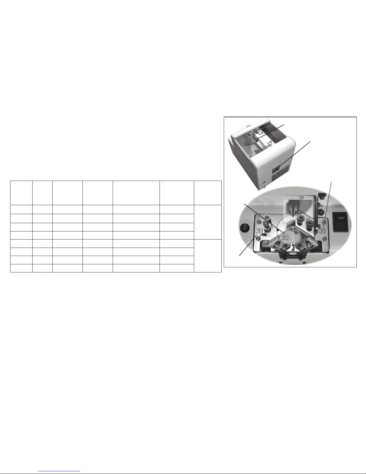
4. NAMES OF MACHINE PARTS
Light-emitting sensor
Light-receiving sensor
Front cover
Rear cover
Right side cover
Rail
Escaper
Passing plate
Brush
DC jack
Timer knob
Vibration adjusting bolt
(under the machine)
LED Screw sensor
Stopper assembly
Sensor bracket at-
taching bolt
Escaper bracket attaching
bolt
Bit guide bracket
Rear cover
xing screws
(2-left/2-right)
Stopper
Scooping chamber Rail xing bolt
Bit guide
Upper cover
Left side cover
Vibration adjusting plate x-
ing bolt
Power switch
Scooping block
left and right
(moving up and down)
Escaper guide-right
5. ADJUSTMENTS AND CHECKS BEFORE USE
5-1. Checking the model number of the main body
Check if the machine has the parts which match the nominal diameter of the
screws to be loaded. Check the model number of the rail, escaper, stopper
assembly, escaper guide-right and passing plate by referring to the following
table. Each escaper, stopper assembly and escaper guide-right is stamped with
a model number which corresponds with the type of screws that can be used.
Screw
feeder
model
Screw
size
Rail model
No.
Escaper
model No.
Stopper assembly
model No.
Escaper
guide-right
model No.
Pass-
ing plate
modelNo.
HSV-10 M1.0 HSV-BI-10 HSV-SIE10 HSV-TPO20806-10 HSV-SIEM10
HS3-
02052-1
HSV-12 M1.2 HSV-BI-12 HSV-SIE12 HSV-TPO20806-12 HSV-SIEM12
HSV-14 M1.4 HSV-BI-14 HSV-SIE14 HSV-TPO20806-14 HSV-SIEM14
HSV-17 M1.7 HSV-BI-17 HSV-SIE17 HSV-TPO20806-17 HSV-SIEM17
HSV-20 M2.0 HSV-BI-20 HSV-SIE20 HSV-TPO20806-20 HSV-SIEM20
HS3-
02052-2
HSV-23 M2.3 HSV-BI-23 HSV-SIE23 HSV-TPO20806-23 HSV-SIEM23
HSV-26 M2.6 HSV-BI-26 HSV-SIE26 HSV-TPO20806-26 HSV-SIEM26
HSV-30 M3.0 HSV-BI-30 HSV-SIE30 HSV-TPO20806-30 HSV-SIEM30
Note: Screws, with a different nominal diameter, can be used by replacing the rail, escaper, stopper assem-
bly, escaper guide-right and passing plate. The parts, for replacement, are available separately.
Before delivery, each section of the machine is checked and adjusted with panhead screws matching the nominal diameters of the
ordered model. Most screws may be usable in the initial status of adjustment however, if the height or shape of the screw head
is different or if the operation is regarded as abnormal, each section must be readjusted. If this is the case, make the following
checks and adjustments:○Check the screw load amount ○Check and adjust the brush ○ Check and adjust the passing plate
○ Check and adjust the rail vibration ○ Check and adjust the holding plate
○ Check and adjust the front & rear sides of the rail ○Check and adjust the timer
If the rail, escaper, stopper assembly, escaper guide-right and passing plate, of the machine, are replaced, screws with a different
nominal diameter can be accepted. After these parts are replaced, ne adjusting is required. The respective adjusting procedures
will be described elsewhere. Please read these procedures. - 6 -
Escaper identication
stamp
Stopper identication
stamp
Escaper guide-right
identication stamp
Rail identication seal
Passing plate identication seal

5-2. Amount of screws to be loaded
An excessive amount of screws, loaded into the chamber, will have an
adverse effect on the screw alignment and transport. The gure, shown
at right, indicates the maximum amount of screws to be loaded. Use
this as a guide when loading the screws.
・ Turn the power switch ON and OFF so that the scooping block is at the
lower limit position.
・ Load screws up to approximately 2-3 mm below the rail surface.
・ At this time, check that screws are not loaded so as to cover the upper
portion of the inclined plate.
・ Be sure to determine the screw load by observing the machine while it is
in operation.
5-3. Checking and adjusting the brush
Turn OFF the power supply before checking and adjusting.
Load the screws into the scooping chamber, turn ON and OFF the
power switch so that screws are aligned into the rail groove.
・
Turn ON and OFF the power switch so that the brush bristles are in a
horizontal position as shown in the gure at right.
・
Check that the heads of the screws, in the rail groove, are in slight con-
tact with the brush bristles.
・
When the brush height is too high or low, this will have an adverse effect
on the screw alignment and transport.
・
If any adjustment is necessary, loosen the brush height adjusting bolt to
adjust the brush height.
・
If the plastic portion, at the front of the brush, comes into contact with the
passing plate, loosen the brush assembly mounting screw and make an
adjustment either backward or forward.
・
Operate the machine to check that the brush operation is normal.
- 7 -
Screws, loaded into the chamber, must not be above the
rail-groove surface.(The maximum screw load must be
2-3 mm below the rail-groove surface.)
Loaded screws
Brush
Brush height
adjusting bolt
Brush assembly attaching
screw
The brush must not
be in contact with the
passing plate when it
moves.
Passing plate
This inclined surface, on both the right and left inclined
plates, should be visible.
Power switch
Turn On and Off the power switch
to put the brush bristles in a hori-
zontal position.
Move the brush by hand to
check that the screws, in the
rail groove, are in slight contact
with the brush bristles and
make adjustments if necessary.
Power switch

5-4. Checking and adjusting the passing plate
Turn OFF the power switch before making any checks or adjustments.
・
Check that the passing plate is adjusted to a height that permits loaded
screws to pass just within the clearance limit.
・
If the passing plate is too low, screws cannot pass.
If the passing plate is too high, it will hamper a smooth transport of the
screws.
・
If adjustment is required, loosen the passing plate attaching bolt and ad-
just the height.
・
After making an adjustment, do an operational check.
Note: Using the half-presses on both sides of the passing plate as guides,
slide the passing plate up or down.
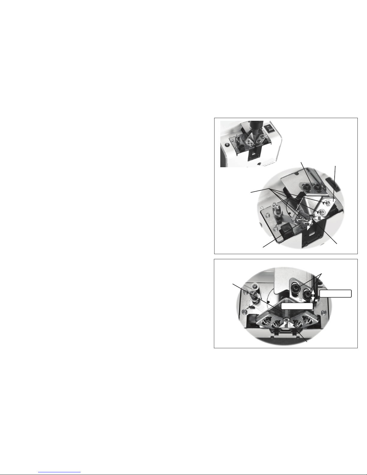
5-5. Checking and adjusting the rail vibration
This machine’s rail vibration can be adjusted.
The screw transport speed differs depending on the screw type.
Check the screw transport speed. If the rail vibration hinders a smooth
transport of the screws, it can be adjusted.
・
Loosen the anti-vibration bolt at the rear of the machine. Next, turn the vi-
bration adjusting bolt, located on the bottom of the machine, to adjust the
vibration. When the bolt is turned clockwise, as viewed from the bottom of
the machine, the vibration will increase. When the bolt is turned counter-
clockwise, the vibration decreases.
・
If the vibration is adjusted to a too large a value to increase the transport
speed, the rail will hit against the escaper and screws may fall into the
machine from the clearance, failing to unload screws normally. Adjust the
vibration to a proper value that matches the loaded screws.
(Related item: Check and adjust the front and rear positions of the rail.)
・
After making an adjustment, be sure to tighten the anti-vibration bolt.
・
After making an adjustment, do an operational check.
- 8 -
Passing plate
Loaded screw
Passing plate
attaching bolt
Half-press
(provided on both sides
of the passing plate)
The clearance should be just enough to permit the loaded screws
to pass through the passing plate.
Weaker vibration
Vibration adjusting
plate xing bolt
Vibration
adjusting
bolt
Stronger vibration
The rail must not come in contact
with the escaper. The clearance
must not be too large.

5-6. Checking and adjusting the height of the bit guide
bracket
Check the height of the bit guide bracket.
・
Check that the clearance between the head of the loaded screw, in the
rail groove, and the bit guide bracket is 0-1 mm.
・
If there is no clearance, a screw will be caught.
If the clearance is too large, a screw pile or screw jump will occur.
・
If adjustment is required, loosen the bit guide bracket attaching bolt and
make an adjustment either up or down.
・
If the bit guide bracket hits against the escaper, it will hinder the escaper
motion.
・
After making an adjustment, check the machine operation.
5-7. Checking and adjusting the front/rear positon of the
rail
If the rail comes into contact with the escaper, or the clearance be-
tween the rail and escaper is too large, when the machine is operated,
loosen the rail xing bolt and adjust the rail either backward or forward.
After making an adjustment, be sure to tighten the rail xing bolt.
・
If the rail hits against the escaper, the escaper will not function properly.
・
If the clearance between the rail and the escaper is too large, screws
may fall into the machine.
After making an adjustment, try making a vibration readjustment by
referring to “Checking and Adjusting the Rail Vibration”.
- 9 -
The bit guide bracket must not come into
contact with the escaper.
Rail xing bolt
Adjust the rail
either backward
or forward.
Bit guide bracket
Loaded screw
Escaper
Bit guide bracket
attaching bolt
Up/down
adjustment
The clearance between the bit guide bracket and the head of
the loaded screw should be 0-1 mm. The bottom of the bit
guide bracket should be parallel to the rail-groove surface.
- 10 -
5-8. Checking and adjusting the bit guide
Check the bit guide position.
・
Adjust the bit guide to a position where the user can easily extract
screws.
・
Try extracting screws a few times in order to adjust the position of the
bit guide.
・
Adjust the bit guide by loosening the attaching bolts.
◎Adjusting the guide plate
・When it is difcult to pick up screws with the bit, adjust the
guide plate.
・
Loosen the guide attaching screw and adjust the guide plate by
inserting the bit being use.
・
After adjustment, check if pick up, with the bit being used, is smooth.
◎Adjusting the groove between the bit guide and the guide plate.
・
The groove position between the bit guide and the guide plate should
be such that it is easy for the user to extract screws.
・
Adjust the groove position by loosening the bit guide attaching bolt.
・
After adjustment, check that the extraction of screws is smooth.
Check if it's easy to extract
screws.
Screw
Left guide plate
Right guide plate
Guide attaching
screw
Bit guide
Screw
Bit guide
The bit guide attach-
ing bolts
Adjustment
Adjustment
- 11 -
5-9. Checking and adjusting the timer
The screw transport feed differs depending on screw type. This ma-
chine can make screw unloading smooth through timer adjustment.
For screws with a low transport speed, set the timer long. For screws
with a high transport speed, set the timer short.
・
This machine continues its operation when no screw is found at the
screw extraction site. The machine continues operating with a screw at
the extraction site but will stop, after a certain lapse of time, if the screw
is not extracted. This time lapse can be varied by adjusting the timer.
After the screw is extracted, the machine starts operating again.
・
Check the operation by intercepting the optical axis of the sensor.
・when there is a screw present in the escaper with the main power ON.
use a nger or an object to block out the ultrared sensor, and switch on
the power again.
・
Make an adjustment with the timer knob at the rear of the machine body
(as shown in the gure on the right).
・
When the timer knob is turned clockwise, as viewed from the rear side,
the time becomes shorter.
When the knob is turned counterclockwise, the lapse time becomes longer.
・
Make this adjustment, by using the accompanying screwdriver, within
the allowable turning range, without using excessive force.
・
Do an operational check with screws loaded in the scooping chamber
and set the timer properly.
Adjust the timer with
the timer knob.
When the optical
axis of the sensor is
intercepted, the timer
will function to stop
the operation of the
machine.
Longer
Shorter
Timer knob

5-10. Operation
○Loading the screws (cf. p7)
・
Open the upper cover.
When the chamber plates are at their lowest position, load screws up to 2-3 mm below the rail groove surface.
・
Check that the screws are not loaded so as to cover the upper portion of the inclined plates.
[CAUTION] Do not overload the chamber with screws otherwise it may cause a malfunction or damage the machine.
○Turning ON the power
・
Plug the attached AC adapter into the main body and power outlet.
[CAUTION] Do not use any AC adapter other than the one included with this unit, as it may cause damage.
・
When the power switch is turned ON, the power switch lamp lights up. The scooping block starts to move up and down. The rail
starts to vibrate and the escaper starts rotating.
・
Screws move along the rail towards the rotating escaper which selects one screw at a time.
・
The escaper rotates and deposits the selected screw at the extraction site.
・
At this moment, the sensor detects a screw and the screw sensor LED lights up and then the operation stops.
・
Until a screw is extracted, the machine stops operating.
・
When a screw is extracted, the sensor detects this and the sensor LED light goes off and the machine resumes operation.
○Pick uping Screws
・
Screws can be extracted with an electric screwdriver using a magnetized bit.
・
Use the bit guide to put the screwdriver down vertically into the screwhead’s slots, then pull the screwdriver, horizontally, to-
wards you as extracting the screw.
To insert the screwdriver bit into the screwhead slots properly, it may be necessary to twist the driver slightly.
・
When inserting the screwdriver into the screwhead slots, do not use
excessive force as it may alter the position of the escaper or cause
damage to the machine.
- 12 -

[Reference] Refer to the following table for the recommended bit sizes.
5-11. Maintenance
A dirty rail groove may interfere with the screw transport speed.
Clean the dirty rail with a soft, clean cloth dipped in alcohol.
If cleaning is difcult, remove the rail from the machine and clean the
rail groove. Before removing the rail from the machine, be sure to
turn off the power supply and take the screws out of the chamber.
If there is any dirt or a aw in the rail groove that may cause an im-
pediment in use, we recommend the user to replace the rail.
- 13 -
Loosen the rail xing bolts and pull out the rail
assembly from the rear side of the machine.
Clean the rail
groove.
Rail xing bolt
Put the screwdriver down
vertically and insert the bit
into the screwhead slots
properly.
Pull the screwdriver towards you, hori-
zontally and extract the screw.
Model No. Screw size recommended bit size
bit size screwhead slot No.
HSV-10 M1.0
∅1.5 No.0
HSV-12 M1.2
HSV-14 M1.4
HSV-17 M1.7
HSV-20 M2.0 ∅2.0 or ∅2.3 No.0 or No.1
HSV-23 M2.3
HSV-26 M2.6 ∅3.0 No.1
HSV-30 M3.0 ∅3.2 No.2

6. PARTS ADJUSTMENTS AND REPLACEMENTS
The brush and main motor are consumable parts. When using a different diameter of screw, the following items
must be replaced: rail, stopper assembly, escaper and escaper guide-right.
These parts may be ordered separately. The replacing and adjusting procedures are described below.
When replacing any parts, a ne adjustment is required. Make these ne adjustments by reading the corresponding
contents carefully. Before replacing any parts, be sure to remove all the screws from the chamber.
6-1. Replacing and Adjusting the Brush
Turn OFF the power switch before starting replacement and ad-
justment.
If the brush is too worn to sweep screws off of the rail, replace it.
A brush with harder bristles, than the standard brush, is available asan
option. Consider its convenience when the situation requires it.
・
Turn ON and OFF the power switch in order to set the brush at the posi-
tion shown in the gure on the right and detach the brush assembly.
・
The brush assembly can be disassembled as shown in the gure on the
right.
・
For assembly, reverse the disassembling procedure.
・
After completing the assembly, check that the front part of the brush
doesn’t come in contact with the passing plate. The ideal clearance is 0
mm.
・
For adjustment, refer to “Checking and Adjusting Before Operating the
Machine”.
Part number of brush: HS3-02053 (standard brush)
Brush assembly
attaching screw
Brush
assembly
Passing
plate
When the brush is operating,
it should not come in contact
with the passing plate.
Brush
Passing
plate
Spring washer
Hex socket head small bolt
M2.6×10
M2.6
M2.6
Plain washer
Brush bracket#1
Brush bracket#2
Brush
- 14 -

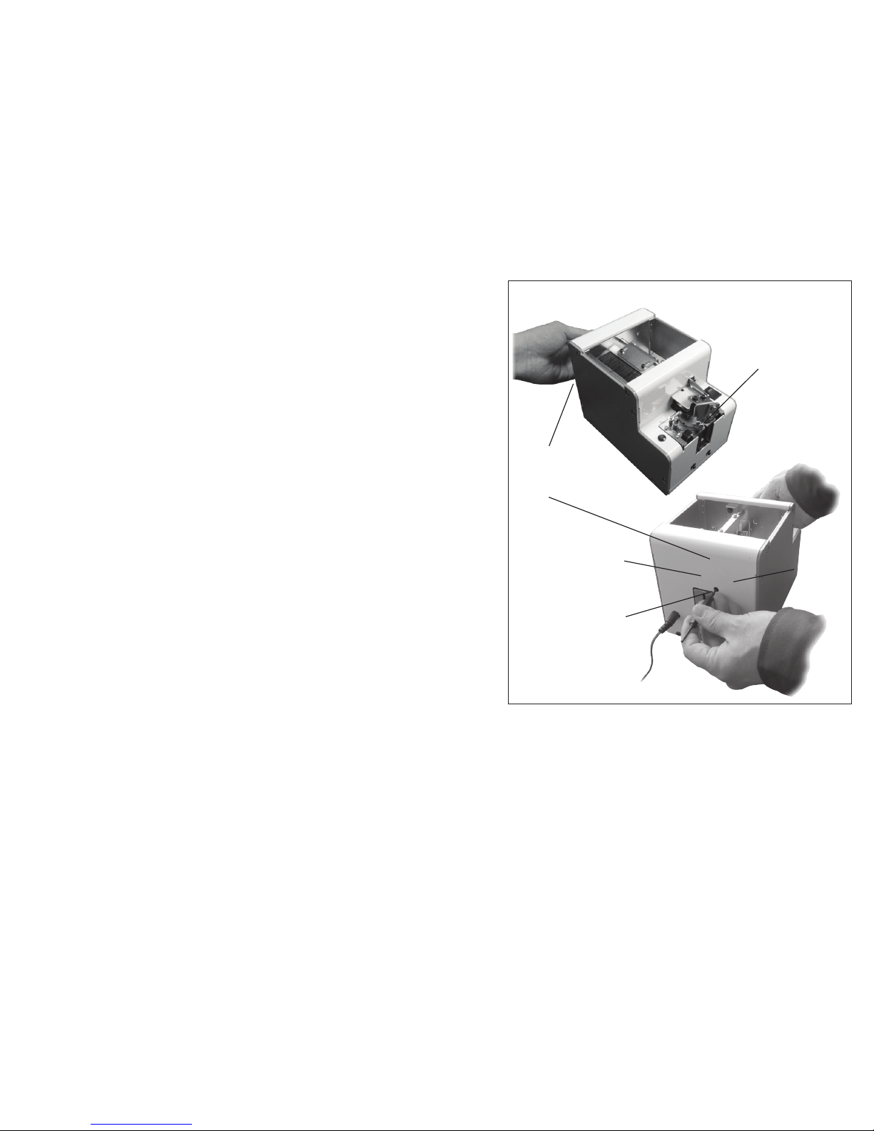
- 15 -
Remove the cover.
Disconnect the motor
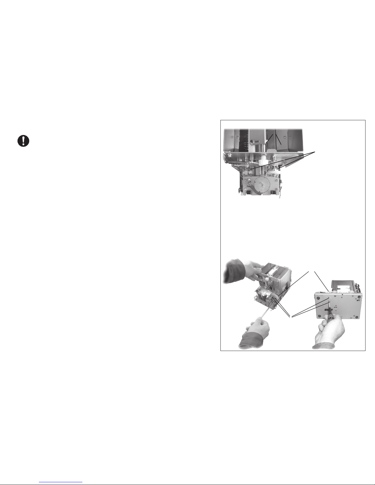
connector.
Remove the motor
attaching screws.
M2.6 X 8 2 pieces
Remove the motor
attaching bracket
towards the rear.
Pull the motor out towards the rear.
main motor unit
6-2. Replacing the Main Motor
Turn OFF the power switch before starting to replace and ad-
just the main motor.
When the motor is damaged, replace it with a new one.
・
First, remove the cover from the main body.
Then, disconnect the connectors for the power switch and LED screw
sensor. This makes it easier to work within the body.
・
Disconnect the motor junction connector.
・
Remove the motor attaching screws on the bottom of the main body.
・
Pull out the motor from the rear side of the main body.
(If the motor is hard to pull out, insert an Allen wrench into the oblong
hole in the base of the body and push the motor attaching bracket
backward.)
・
For reassembly, reverse the disassembling procedure.
The combination of the operation timing for the left and right scooping
blocks is shown on the next page.
Note: Do not use excessive force with the motor wiring in order to avoid
wire breakage.
Part number of main motor unit:HSVRB-09105-15
- 16 -
・ Assemble the motor section when the scooping blocks left and right
are in the lowest position.
・ To get the left and right scooping blocks at almost the same height,
clinch the drive gear of the motor shaft and the gears on the left and
right, and tighten the motor bracket. (M2.6 x 8 - 2 pieces)
The left and right scooping blocks should be at the lowest posi-
tion.
Right driving shaft bracket
Attaching screws
at 4 positions
When it is hard to get a proper gear engagement,
loosen the right driving shaft bracket
then adjust the gears and tighten the screws.
When the right
pin is vertical, the
left pin should be
inclined about 46
°
.
○Operation Timing After Replacing the Main Motor
Turn OFF the power switch before starting to replace and ad-
just the main motor.
・
To adjust the timing of the scooping block in respect to the brush move-
ment, it is necessary to adjust the gear engagement.
・
When the motor has been removed from the main body, adjust the gear
engagement of the motor, as shown in the gure on the right, then the
operation timing can be adjusted.
・
When it is hard to engage the driving gear, of the motor, with the driven
gear, loosen the drive shaft bracket (right) then this will facilitate the as-
sembly. (Refer to the gure on the right.)
After assembling the motor, be sure to tighten the screws again.
・
After installing the motor, switch the power ON to check the operation
timing. (Check that both right and left scooping blocks operate almost
simultaneously.)
・
After doing an operation check, return the wiring arrangement to its orig-
inal status. When installing the cover, be careful not to pinch any wires.
Be careful that the wiring does not hinder the operation of moving parts.
The wiring, on the inside, should not hinder adjustment made from the
outside of the machine.
NOTE:
To avoid breakage, do not use excessive force with the motor wiring.

Loosen the rail xing bolts and remove the rail assembly
from the rear of the machine.
Rail xing bolt
Attaching boltPassing plate
Half-press
(Provided on each side
of the passing plate.)
- 17 -
6-3. Replacing the rail
Turn OFF the power switch before starting to replace and adjust
the rail.
The rail of this machine can be easily replaced.
If there is any dirt or aw on the rail groove that prevents a smooth op-
eration, we recommend the user clean or replace the rail.
Use the passing plate, rail and escaper that correspond to the diameter
of the screws loaded.
Remove any screws that were loaded in the chamber before doing
any replacing and adjusting.
Loosen the rail xing bolts and pull out the rail assembly from the rear
of the machine. After replacing the rail, each part must be adjusted.
6-4. Replacing the Passing Plate
Turn OFF the power switch before starting to replace and adjust
the rail.
Use the passing plate, rail and escaper that correspond with the diam-
eter of the screws loaded.
The following are passing plate numbers which correspond with the
model numbers:
1.0 - 1.7 corresponds with Model No. HS3-02052-1
2.0 - 3.0 corresponds with Model No. HS3-02052-2
Please check that the model numbers correspond with the screws
that can be used.
Remove the passing plate. Do not lose the attached bolts. Using bolts other than those supplied with this machine may re-
sult in a malfunction.
When installing, use the half-press on both sides of the passing plate as guides. After replacement, make the adjustments
that correspond with the screws loaded.

The surface of the escaper should be
lower than the surface of the rail.
Rail surface
Escaper surface
Line up the rail groove
with an escaper notch.
No contact with the side of the rail, the stopper assembly and
the escaper guide-right.
- 18 -
6-5. Replacing and adjusting the escaper, the stopper
assembly and the escaper guide-right
Turn OFF the power switch before replacing.
Turn ON the power switch when adjustments are necessary.
When using screws with a different diameter, replace the escaper,
the stopper assembly, the escaper guide-right, the rail and the pass-
ing plate.
Before replacing the parts, remove all the screws from the
chamber.
First, remove the bit guide attaching plate and then replace and ad-
just the parts.
After replacement, be sure to adjust and check the parts in the area
of the escaper.
(Summary of the adjustment)
Adjust moving parts to correspond with the rail.
In terms of height, the level of the escaper surface should be lower
than the level of the rail surface.
Line up the rail groove with an escaper notch at the end of the ref-
erence point run. A reference point run is the detecting of the start-
ing point of the escaper motor rotation. Also, make sure there is no
contact with the side of the rail and the robot escaper guide.
Rail
Power
switch
Light-emitting sensor
Stopper as-
sembly
Bit guide attaching
plate
LED screw
sensor
Escaper Attaching bolt
for bit guide
attaching
plate
Light-receiving sensor
Escaper
guide-right

- 19 -
①. Replace the escaper, stopper assembly and escaper
guide-right.
Before replacement, remove any screws that were loaded in the
chamber.
First, remove the bit guide attaching plate, then replace and adjust
the parts.
As looking at the front of the machine, start by removing the parts
from the right side.
Start by removing, in this order:
the escaper guide-right → escaper
→spring holder (xing the stopper assembly with screws)→
stopper assembly.
When you remove the spring holder, you can remove the flathead
screw under the stopper.
Do not lose the attaching screws and spacer.
For assembly of the replacement parts, reverse the disassembly pro-
cedure.
After installing the spring holder, assemble the spring as shown in
the gure at right.
The escaper notch needs to be adjusted to the rail groove position
later. Assemble the escaper loosely as it will need adjusting later.
Escaper guide-right
Escaper
Lastly,
remove the
stopper
assembly.
Spring holder
Spring holder
Stopper
assembly
Escaper Escaper guide-right
Bit guide attach-
ing plate
Spring holder
Stopper
Attaching bolt
for bit guide
attaching plate
Stopper
Longer spring arm
is on the upper
The spring arm
should be under the
washer
Shorter arm of the spring should be placed to
the left side of the bent edge of the stopper.
This manual suits for next models
7
Table of contents
Other HIOS Power Tools manuals


