HIOS PG Series User manual

Brushless Screwdriver with Built-in Torque Sensor
PG Series
PG-3000 / PG-5000 / PG-7000
Control Unit
PG-01
User's Manual
ET-A034 22A

Table of Contents
03 Important Safety Instructions
04 Checking Supplied Accessories
05 Setting Up the Device
■Connect the Cords
■Install the Bit
Remove the Bit
■Turn On the Power
06 Parts and Their Functions
■PG-3000/PG-5000/PG-7000
■PG-01
09 Start and Stop
■Start the Screwdriver
■Stop the Screwdriver
09 Adjust Torque
■Reference Table of Output Torque
10 Set Learning Values (Teaching)
■About Learning Values
11 Evaluation of Screw Tightening
■OK/NG Judgment of Tightening Torque Value
■Evaluation of Operation Time
■Flowchart of Judgment
14 Connect the ScrewDriver to PC
■Check the Port
In Case of Windows 10
■Data Output Format by Either RS-232C or USB Connection
Error-related Output
Measurement Judgment Output
■PC Input
Hyper terminal (Example: Windows XP)
Example of a Measurement OK Message
Abnormal Conditions
■Data Taking-in Sheet (HIOS-PG-0611-V2-2_5)
Operating Environment
Conguration of the Screen
Other Sheet
■Collection of Screwdriver Data (Application)
20 Troubleshooting
21 After-sales Service
21 Specications
■External Dimension Drawing
■Specications of PG-01

03
Installation
◦Do not install the device at the places described
below. Otherwise, it may cause a re or a failure.
A place of high humidity or with a lot of dust
・A place where it becomes high temperatures
・A place of re
・A place of direct sunshine
・A place containing corrosive gas in the air
・Unstable place
◦Do not use the device where the ambient
temperatures are out of the range of 5 to 40 °C.
Power Supply
◦Be sure to install an earth leakage breaker and a
safety breaker on the commercial power source
before using it.
◦Connect the earth wire to the earth wire
terminal of the outlet. You may have an electric
shock without the earth wire connection in case
of an electric leakage.
◦Avoid the octopus foot wiring and use of an
extension cord. Otherwise, it may cause a re or
an electric shock.
◦Do not connect anything other than specied to
the connection part of this device. Otherwise, it
may cause an electric shock or a failure.
Handling
◦Do not wear clothes with ippers on the cus,
gloves, neckties etc. Otherwise, they may get
caught in the rotating screwdriver and cause an
injury or a failure.
◦Wear suitable clothing and protective eye-wear
for work. Cover long hair with a hat etc. so that
you can work safely.
◦Turn o power when you leave the workplace,
or when you attach / remove a bit / an optional
item.
◦If static electricity is charged, you need to
neutralize it before use.
◦Avoid an unstable place or an unreasonable
posture for work. Otherwise, it may cause an
injury.
◦Long-time work or some types of work may
cause strain on your hands, neck, arms or waist,
causing an injury. Avoid long-time work and take
a break regularly.
◦We recommend use of a balancer to prevent the
device from falling and to protect cords / wires.
◦Hold the plug when you attach / remove the
power cord, screwdriver and so on.
◦Protect cords / wires by not giving damages to
them; not remodeling them; not pulling them;
not bending them forcibly; etc. Also, do not
place heavy items on the power cord.
Otherwise, it may cause a re or an electric
shock.
◦If you detect an uneven rotation, strange noises,
overheating or activation of a breaker, etc., stop
using the device immediately and have it
repaired. However, note that the device may be
overheated depending on the frequency of the
workpiece or screw types. As a countermeasure,
prepare spare screwdrivers of the same model
to extend the tact time and use them alternately,
or review the selection of screwdriver models.
◦Do not overload the device so much that it
cannot clutch. Otherwise, it may cause a failure
of the motor.
◦Do not touch the screwdriver while it is rotating.
Otherwise, it may cause an injury or a failure.
◦Keep your hands and face away from the
rotating section while in use. Otherwise, it may
cause an injury.
◦Remove the bit from the screwdriver when you
Important Safety Instructions
Please read this manual and the power supply unit manual carefully before use to ensure proper operation. In
addition, do not use the product in the way not described in this manual. Please note that we are not responsible
for any problems caused by using the product in a manner that does not conform to the contents of this manual,
using it improperly, or repairing / modifying by a third party except by us or someone specied by us.

04
Checking Supplied Accessories
If an item is missing or damaged, contact the store where you purchased the product.
◦Screwdriver
◦Bit
◦Screwdriver Cord (2m)
◦Sensor Cord (1.7m)
◦PG-01
◦AC Adapter
◦RS-232C Cable
◦USB to RS-232 Conversion Cable*
◦Manual
◦User Software CD-ROM
* Please download and install the device driver for the USB to RS-232 conversion cable from the ATEN
website.
are not working.
◦If you cannot attach / remove the bit in the way
described in this document, please make
contact with our service section.
◦Fix the workpiece with jig / clump while in
working.
◦Do not use the switch lever as a hanger.
Otherwise, it may cause an accident or an injury.
◦Do not give a strong impact or excessive force.
Otherwise, it may cause a failure.
◦Do not operate the screwdriver with wet or oiled
hands.
◦Do not operate the FOR / REV switch before the
screwdriver completely stops. Otherwise, it may
cause a failure.
◦Do not disassemble / remodel this device.
Otherwise, it may cause a failure.
◦High torque has a large recoil on the hand or
arm. Hold the driver rmly to avoid being swung
around.
Maintenance and Inspections
◦Turn o power and remove the power plug from
the outlet when the device is not in use for a
long time.
◦Remove the accessories from the screwdriver
and store them in the package box when it is
not in use them for a long time.
◦Inspect the device regularly to conrm there are
no damages. If you use it with damages, it may
cause a re or an electric shock.
◦When you clean the device, turn o the power
and remove the power plug from the outlet.
Otherwise, it may cause a re or an electric
shock.
◦Use dry cloth to wipe of dust or stains. The dust
may absorb moisture to allow current to ow,
causing a re.
◦Store the device in a place where the
appropriate temperatures and humidity are
controlled.
◦Do not store the device in an unstable place or a
place with vibrations. Otherwise, it may cause a
failure.
◦Keep the device out of reach of anyone but
people involved in the workpiece.
◦We recommend genuine HIOS parts for
replacement.

05
Setting Up the Device
■Connect the Cords
Connect all the attached cords.
After all cords are successfully connected, put the power plug into an outlet.
CAUTION
◦Make sure the combination of the screwdriver and the power supply is appropriate.
◦Make sure the power is o.
❶Connect the plug and screwdriver cord to the power supply.
❷
Connect the screwdriver and sensor cords to the screwdriver and connect the sensor cord to
PG-01.
❸Connect the AC adapter to PG-01.
■Install the Bit
CAUTION
◦Do not install or remove the bit with the power on. It may cause an accident.
❶Insert the bit while pushing the joint shaft collar into the body.
❷Release the collar and check if the bit is locked.
◦Pull the bit gently to conrm it does not come out.
Remove the Bit
❶Pull out the bit while pushing the collar against the body.
■Turn On the Power
❶Turn on T-70BL and PG-01.
CAUTION
PG-01 automatically performs zero-adjustment when the power is turned on. Do not apply a load to
the tip of the screwdriver or do not start the screwdriver during the adjustment.

06
Parts and Their Functions
■PG-3000/PG-5000/PG-7000
❶ ❽❼❻❸❷ ❹ ❺
❶ ❽ ❼❻❸❷ ❹ ❺
❶ ❽❼❻❸❷ ❹ ❺
❶Joint shaft collar
Operate the collar to install or remove the bit.
❷Nut protection cover
This protects the torque adjustment nut. Turn it counterclockwise for removal.
❸Torque adjustment nut
Use this for adjustment of the output torque.
❹Switch lever
Start the screwdriver with the lever.
❺Forward / reverse switch
You can switch the screwdriver’s rotational direction.
: Clockwise
OFF: no rotation(PG-5000/PG-7000)
: Counterclockwise
❻Screwdriver cord connector
To connect the screwdriver cord.
❼Hanger
To hang the screwdriver on the balancer or like.
❽Sensor cord connector
To connect the sensor cord.
PG-3000
PG-5000
PG-7000

07
■PG-01
The measurement result of tightening a screw will be informed by the indicator and sound.
Control Unit
❶
❽ ❼ ❻❾❿⓫
❸❷ ❹ ❺
⓬ ⓭
⓮⓯
❶L.NG Indicator
This indicator is lit when the measured value is no good (smaller than the minimum pass value).
❷L.G Indicator
This indicator is lit when the measured value is good (larger than the minimum pass value and below
the minimum learning value).
❸GOOD Indicator
This indicator is lit when the measured value is good (larger than the minimum learning value and
smaller than the maximum learning value).
❹H.G Indicator
This indicator is lit when the measured value is good (larger than the maximum learning value and
below the maximum pass value).
❺H.NG Indicator
This indicator is lit when the measured value is no good (larger than the maximum pass value).
❻Teaching Indicator
This indicator is lit when in the teaching mode (for setting of learning values).
❼Teaching Button
This is for setting to the teaching mode. Pressing and holding this button (2 seconds or longer) in the
teaching mode will cancel the mode. For details of teaching, refer to "Set Learning Values (Teaching)"
(P.10).
Back Side
Front Side

08
❽OPERATION OK Indicator
This indicator is lit while the screwdriver is rotating positively.
❾OPERATION NG Indicator
This indicator is lit when the operation ends without torque up. This blinks when the operation ends
due to an abnormal measurement time.
❿Power Button
This switch turns power on and o. Press and hold the button for 2 seconds to turn o the power.
⓫Power Indicator
This indicator is lit when power is supplied.
⓬Sensor Cord Connector
This is used to connect the sensor cord.
⓭I/O Connector
The I/O at cable is connected here for the evaluation result to be output. The output format is an open
collector. Use this when you cannot connect with RS-232C.
111
1919
19
22
2202020
PIN No. Output signal Description
12 COM GND —
13 L.NG (NG) Output when the measurement value is NG (below the minimum pass
value)
14 L.G (OK) Output when the measurement value is OK (equal to or larger than the
minimum pass value and smaller than the minimum learning value)
15 GOOD (OK)
Output when the measurement value is OK (equal to or larger than the
minimum learning value and smaller than the maximum learning
value)
16 H.G (OK)
Output when the measurement value is good (equal to or larger than
the minimum learning value and smaller than the maximum learning
value)
17 H.NG (NG) Output when the measurement value is no good (larger than the
maximum pass value).
⓮RS-232C Connector
An RS-232C cable is connected here.
PIN No. Signal name I/O
2 RXD OUT
3 TXD IN
5 GND
⓯AC Adaptor Connector
An AC adaptor is connected here. Power will be automatically supplied when an AC adaptor is
connected.

09
Start and Stop
■Start the Screwdriver
❶Pull the switch lever to start the bit turning. Release it to stop turning.
■Stop the Screwdriver
❶When the set torque is reached, the clutch in the screwdriver works to stop turning.
Adjust Torque
CAUTION
The "reference table of output torque" and the torque adjustment scale are approximate and do not
guarantee actual setting values.
For accurate torque check, please use an HIOS torque meter and Fidaptor.
❶If the torque is determined beforehand, turn the torque adjustment nut and nut xing ring
referring to the "reference table of output torque".
◦Turn the torque adjustment nut clockwise to increase the torque and turn
it counterclockwise to decrease the torque.
◦Adjust it so that the end face of the nut xing ring is right above the scale.
◦After the nut xing ring is positioned, t the torque adjustment nut
accordingly.
❷Try to fasten a screw and check how it is fastened after the screwdriver stops and adjust the most
appropriate torque.
■Reference Table of Output Torque
PG-3000PG-3000
Torque Scale
1
0.3
0.2
0.5
0.55
0.4
N·m
2345678
PG-5000PG-5000
Torque Scale
1
0.4
0.6
1.0
0.8
1.2 N·m
2345678
PG-7000PG-7000
Torque Scale
1.0
1.4
1.2
1.6
2.0
1.8
2.6
2.2
2.4
2.8 N·m
21 3 4 5 6 7 8 9 10

10
Set Learning Values (Teaching)
Measure the "tightening torque" and "working time" by using screws and materials actually used to set
the reference values for work. The two values recorded are the minimum and maximum, respectively.
Also, after teaching, it is possible to change the error tolerance of the learning values and the learned
values in the attached application or Excel le.
CAUTION
Teaching should be done under the same conditions as actual operation.
An error may occur in the measured value if the screw to be used, the materials to be fastened, the
attaching method of the screw, etc., are different from actual operation.
❶Press and hold the teaching button.
Control Unit
◦A buzzer sounds in about 2 seconds and the teaching mode is enabled.
◦The teaching indicator is lit.
◦L.NG indicator and H.NG indicator blinks.
❷Using the screws and materials to be actually used, perform tightening more than 3 times.
◦Every time after tightening is completed, a buzzer sounds once, and the measured value is recorded.
◦
The measured values of the third to tenth trials are recorded and the values after the eleventh trial
will overwrite the old values.
❸Press and hold the teaching button.
◦A buzzer sounds in about 2 seconds and the teaching mode ends.
◦The teaching indicator, L.NG indicator and H.NG indicator turn o.
■About Learning Values
◦The learned values do not disappear even when the power is turned o.
◦To reset the learned values, perform teaching again. The previous learned values will be deleted when
the teaching mode is enabled.
◦After purchasing, please perform teaching with PG-01 for the rst time. Otherwise, it is not possible to
set learning values with the attached application.

11
Evaluation of Screw Tightening
◦
It measures actual screw tightening work in real time, compares the measurement with the learning
value, and informs the user of the evaluation result with a indicator and sound.
◦The reverse rotation of the screwdriver is not evaluated.
◦The allowable error range at the time of purchase is set to 10% for both upper and lower limits. If you
want to change it, please use the attached application.
■OK/NG Judgment of Tightening Torque Value
If no error is detected in the screw tightening work, one of L.G, GOOD or H.G indicator is lit and the buzzer
sounds.
NG NGOK
Learning
value
Allowable error range
Lower limit value
Allowable error range
Upper limit value
Threshold valueThreshold value
If the torque is within the learning values, the GOOD indicator will be lit, and if it falls within the allowable
error range, either L.G or H.G indicator will be lit. Conversely, when the torque is less than the lower limit
value, the L.NG indicator will be lit, and when the torque exceeds the upper limit value, the H.NG indicator
will be lit, which means fail.

12
■Evaluation of Operation Time
◦
The operation time from start of rotation to stop of the screwdriver is evaluated against the learning
values.
◦
The blinking and lighting of the OPERATION NG indicator will turn o when the START signal is entered
again.
Control Unit
Main reasons why OPERATION NG indicator is lit
◦No torque up signal is sent because of reasons like screwdriver idling.
Main reasons why OPERATION NG indicator blinks
◦
A torque up signal was not sent during the learning measurement period.
If it is not necessary to strictly measure the operation time, by using the application, change the setting
value so that the learning interval will become larger.
◦Continuous ON/OFF operations at the end of tightening (pushing the button twice or three times in a
row)
CAUTION
There is a nonintervention time of 100mS for torque measurement and evaluation after the START is input.
Nonintervention time of 100mS
If the screwdriver output is given to a screw even after tightening, the value will be larger than the
measuring value and not the expected tightening value.
To perform proper screw tightening, please do not perform continuous operations.
13
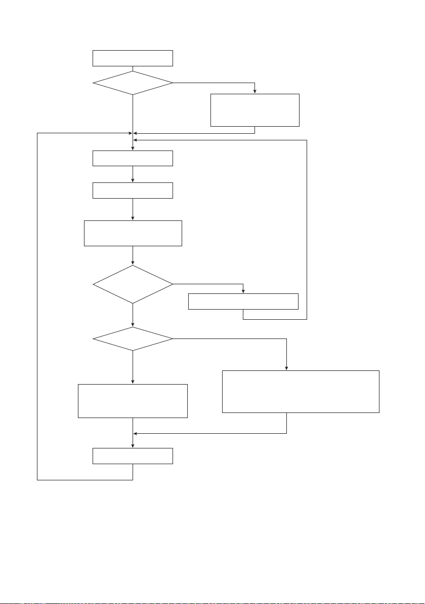
■Flowchart of Judgment
Evaluation
End of tightening
(Torque up signal)
Power ON
Select an operation
Normal operations
Set the judgment value (TEACHING)
Set the evaluated value
TEACHING LED is lit (red)
L.NG & H.NG LED blinks (red)
L.NG, and H.NG blinks
if no teaching value is set.
The set value can be
changed later from the
tabulation software on the
connected PC.
Initial resetting of PG-01
No torque up signal
NG
OK
Tightening ON
LED OFF at completion
OPERATION NG LED ON (red)
OPERATION OK LED ON (green)
One beep
L.G, GOOD or H.G LED ON (green)
One beep
Signal output
L.NG LED or H.NG LED ON (red)
If measurement time is NG, OPERATION NG LED blinks (red)
Two beeps
Signal output
End
14
Connect the ScrewDriver to PC
❶Connect the RS-232C cable to PG-01.
❷Connect the USB to RS-232C conversion cable to the RS-232C cable.
❸Connect the USB to RS-232C conversion cable to PC.
❹Download the device driver from the ATEN website and install it on PC.
Check the website for how to install and supported OSs.
https://www.aten.com/global/en/products/usb-peripherals/usb-converters/uc232a/
❺Turn on PG-01.
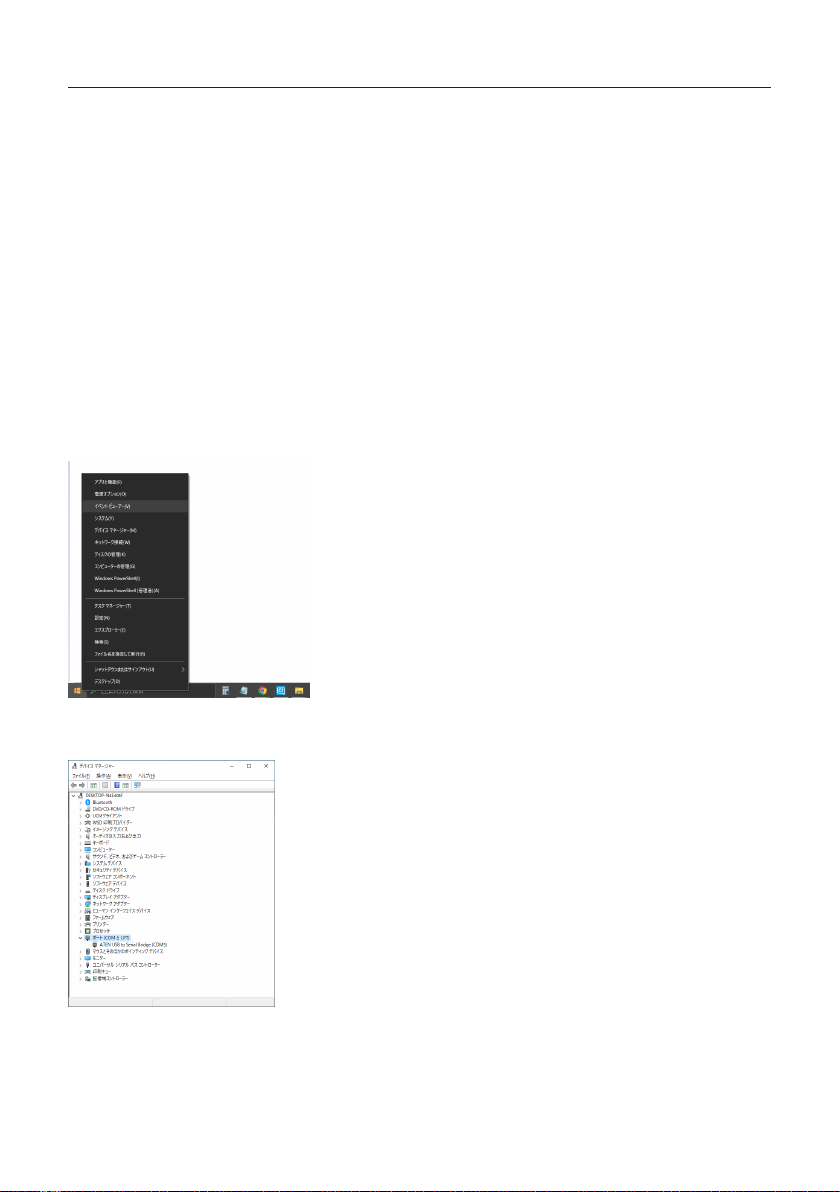
■Check the Port
Open the device manager to check which port PG-01 is connected to.
In Case of Windows 10
❶Right-click the Start button and select Device Manager.
❷Click the port (COM and LPT) in the list and check COM number displayed in <ATEN USB to Serial
Bridge (COMXX)>.

15
■Data Output Format by Either RS-232C or USB Connection
The data for judgment is output for each measurement in the three formats in the sequence below.
・Measurement Data
D10 XXXX XXXXX<LF>
❶ ❷
❶Torque conversion value – 4 digits
❷Measurement time – 5 digits (unit: mS)
・Recorded Learning Value
D00 XXXX XXXX XXXX XXXXX XXXXX<LF>
❸ ❹ ❺ ❻ ❼
❸Display learning number
❹Display learning minimum value
❺Display minimum learning measurement time
❻Display learning maximum value
❼Display maximum learning measurement time
・Judgment reference values
❽ ❾ ❿ ⓫ ⓬
D20 XX XXXX XXXX XXXXX XXXXX<LF>
❽Judgment error rate
❾Judgment minimum value
❿Judgment measurement time minimum value
⓫Judgment maximum value
⓬Judgment measurement time maximum value
Error-related Output
E90 End which cannot be detected by 0 areas, and judged [Zero area detection/Impossible
judgment ending]
E91 Abnormal termination at measurement time [The abnormally end at the
measurement time]
E92 Study shortage and end which cannot be judged
[The ending about which it is
impossible to judge by the
learning
lack]
E93 Judgment=LOW NG [Judgment = Low NG]
E94 Judgment=HIGH NG [Judgment = High NG]
Measurement Judgment Output
E00 Judgment=GOOD [Judgment = Good]
E01 Judgment=LOW OK [Judgment = Low OK]
E02 Judgment=HIGH OK [Judgment = High OK]

16
■PC Input
Hyper terminal (Example: Windows XP)
After the PC is turned on and the version information is displayed, auto-zero correction is performed. The
following messages for debugging are displayed that are not directly related to measurement.
Ver3.04 2022/05/25
[Zero Adj A/D=7C2 G=1EA F=200]
[Zero Adj A/D=806 G=1EB F=200]
[Zero Adj A/D=808 G=1EC F=200]
[Zero Adj A/D=803 G=1ED F=200]
[Zero Adjustment end A/D=7FF Gain=1ED]
Example of a Measurement OK Message
In general, messages are either operation check messages or measurement data.
[Job Num = 4]
S00
[Lever SW ON]
[Job Num = 6]
S02
[Torque UP ON]
Operation check message for debugging
D10026900668
D000005026903150033701891
D2002026303210033001928
Measurement data
M21[Judgment=LOW OK]
E01
[Judgment end]
Operation check message for debugging
Abnormal Conditions
This displays the condition when judgment results are abnormal.
[Job Num = 4]
S00
[Lever SW ON]
[Job Num = 6]
S02
[Torque UP ON]
Operation check message for debugging
D10028600590
D000006009600010000101894
D2002140513090131201931
Measurement data
[Abnormal termination at measurement time]
E91 Operation check message for debugging

17
■Data Taking-in Sheet (HIOS-PG-0611-V2-2_5)
By using the data taking-in sheet in the attached CD-ROM, you can check the OK/NG of screw tightening
on the PC or record the measurement data.
CAUTION
◦Enable macros.
◦Start settings after turning on PG-01 and connecting it to the PC.
◦When using USB, the PC may turn o PG-01 automatically in some cases. In that case, please
disconnect and reconnect the screwdriver.
◦There is no reaction to the reverse rotation of the screwdriver.
◦If you want to take in two types of data, create two les (for example, test1.xls and test2.xls) in
advance. Then, start up two applications, and then open each le.
If you open les by double-clicking them in Windows Explorer, two les are opened in the same
application and the application cannot be used.
Operating Environment
The data taking-in sheet was conrmed to be eective in the following environments:
・Microsoft Windows XP
・Microsoft Excel 2003
If it is not functioning, select application type “screwdriver data collection”.
Please be aware that maintenance and support services are unavailable since this is sample software.
Conguration of the Screen
❶ ❷ ❸ ❹ ❺
❻
❼
❽
❾
❿
⓫
⓬
❶Connection confirmation window

18
The login information is displayed.
❷Disconnect button
This ends data import.
❸Connect button
This makes the data import standby. If the previous data is necessary, please save the current data rst
and then connect the screwdriver. (The previous data will be cleared upon connection.)
❹COM port
Check the port number and enter it. Then, press [Enter] on the keyboard. Usually, select COM as the
port.
Cell colors
・Gray: the screwdriver is not connected.
・Yellow: the screwdriver is connected.
❺LAN settings
Optional
❻Judge On/Off
Errors E90/E91/E92 can be turned ON/OFF.
ON: the measured values are entered in the datasheet.
OFF: the measured values are entered in the irregular sheet.
❼Measurement settings processing table
The table shows commands and settings processing that are displayed in the log.
❽Judgment
This indicates OK/NG of screw tightening with colors.
❾Output data
Torque equivalent value: this indicates values taken during actual operation.
Measurement time: this indicates the time from screw tightening to torque-up.
Number of the learning: indicates the number of teaching operations performed.
Minimum of the learning: indicates the minimum teaching value (modiable).
Maximum of the learning: indicates the maximum teaching value (modiable).
Measurement time of minimum: indicates the teaching minimum time (modiable).
Measurement time of maximum: indicates the teaching maximum time (modiable).
After inputting a number, press [Enter] on the keyboard.
・These learning-related values will be sent to PG-01 by clicking the [Write learn-value] button after
entering a number.
・If the [Learned value change] button is not pressed, the memory in PG-01 won’t be updated and the
previous value will be recovered after the next torque-up operation.
❿Judgment comparison data
Torque value: indicates the value output on the graph sheet.
Judgment minimum value: indicates the amount minus the % setting for the learning minimum value.
Judgment maximum value: indicates the amount plus the % setting for the learning maximum value.
Meas. Time of judge minimum: indicates the amount of the time minus the % setting for the learning
minimum measurement time.
Meas. Time of judge maximum: indicates the amount of the time plus the % setting for the learning
maximum measurement time.
⓫Judgment error rate (%)
This sets the acceptable evaluation threshold before a screw tightening operation.

19
Selecting the judgment error rate while the screwdriver is connected transmits the selected rate to
PG-01. Even after disconnecting the PC, the selected rate will be retained.
The selectable rates: 0%, 2%, 5%, 10% or 20% (02=2%)
⓬Work On
Normally this turns on automatically when an operation is performed.
Other Sheet
データーシート
グラフシート
イレギュラシート
■Collection of Screwdriver Data (Application)
The operation data is collected in the same way as the data taking-in sheet. The data is saved in the CSV
format.
For details, click [Instructions] on the screen of screwdriver data collection.

20
Troubleshooting
If you have any problem while using this machine, please check the items in this section before making
inquiries.
Then, if the problem persists, please contact your dealer or us.
The L.NG or H.NG indicator blinks when the power is turned on.
There is a possibility that the learning values are not set correctly. Repeat teaching 3 times or more to set
the learning values.
The L.NG or H.NG indicator ashes even when the teaching mode is ended and
measurement cannot be performed.
There is a possibility that data for evaluation comparison is insucient. If the learning count is less than 3,
the indicator will keep ashing even if the teaching mode ends. Repeat teaching 3 times or more again to
set the learning values.
In the following cases it is dicult to make an evaluation, and it may not be counted as learning.
・Torque value is 10 or less ("E90" [Zero area detection/Impossible judgment ending])
・Idling of the screwdriver occurs or the measurement time is 100 mS or shorter. ("S01" [Lever switch
O(no torque up)])
Setting cannot be changed from the tabulation software.
Click the [Write learn-value] button after input of a number. The settings in PG-1 will be updated by
clicking the [Write learn-value] button.
The torque is abnormally low or high.
Turn o the power to check if the cords are connected correctly and then turn on the power again.
If the problem persists, replace the sensor cord.
When a Problem Cannot Be Solved
When contacting us, have the following information ready:
・Product name
・Description of the problem (detailed description of the operation performed and its result, etc.)
・Serial number (on the label of the product)
This manual suits for next models
4
Table of contents
Other HIOS Power Tools manuals


